
High Order Sliding Mode Control for Power Regulation: Comparative
Insights with PI Controller CUK Converter Implementation
Muhammed Mahho
a
, Mehmet Yilmaz
b
and Muhammed Fatih C¸ orapsiz
c
Department of Electrical and Electronics Engineering, Ataturk University, Erzurum, Turkey
Keywords:
CUK Converter, Proportional-Integral (PI) Controller, High Order Sliding Mode Control (HOSMC), Energy
Conversion Efficiency.
Abstract:
In this study, the performance analysis of the Higher Order Sliding Mode Controller (HOSMC) and
Proportional-Integral (PI) controller for various scenarios was performed using the DC-DC CUK converter
topology. While performing the performance analysis, the current ripple at the converter output, voltage rise-
fall and convergence time were considered. While comparing the PI controller and HOSMC, the output voltage
boost for the 30V input voltage was evaluated to 60V in the first scenario and to 45V in the second scenario.
In these scenarios, HOSMC showed superior performance compared to PI controller in a shorter time. In the
third scenario, the performance of the controllers was examined to obtain an output voltage lower than the in-
put voltage. In the third scenario, HOSMC provided the desired output voltage at the input voltage level within
0.05s. In this scenario, HOSMC gave more successful results than the PI controller. In the fourth scenario, the
input voltage was transferred to the output at different voltage levels at 1.5s intervals. In the fourth scenario,
for the first 1.5 seconds, HOSMC has shorter settling time than the PI controller. In the second 1.5 seconds,
although the HOSMC experienced some deterioration in the transient state, the desired output voltage values
were reached in the same time as the PI controller.
1 INTRODUCTION
Rapid developments in medical devices, computer
systems and energy production technologies have in-
creasingly increased the importance of DC-DC con-
verters. Converters are among the basic components
that increase energy efficiency by providing different
voltage levels required by electronic devices and sys-
tems (Yılmaz et al., 2025). Used in a wide variety
of applications, from portable devices and electric ve-
hicles to renewable energy systems and communica-
tion infrastructures, these converters not only directly
contribute to design criteria such as size, weight, and
cost, but also improve system performance. The most
frequently preferred among switched non-isolated
DC-DC converters are; Boost converter, Buck con-
verter, Buck-Boost converter, CUK converter and
SEPIC converter. Non-isolated DC-DC converters of-
fer higher efficiency than isolated DC-DC converters
and the advantage of voltage increase/decrease via
a single switching control. Technological advance-
a
https://orcid.org/0009-0005-0938-7031
b
https://orcid.org/0000-0001-7624-4245
c
https://orcid.org/0000-0001-5692-8367
ments and increasing energy demand have enabled the
widespread use of these types of converters. DC-DC
converter topologies are frequently used to reduce en-
ergy conversion losses in charging systems and PV
energy generation systems (Fathabadi, 2016; Mahho
et al., 2025). In today’s conditions, especially in solar,
wind, proton exchange membrane fuel cells and sim-
ilar energy production systems, the energy produced
is low and the current is not constant (Refaat et al.,
2024). In such systems, DC-DC converters play a
critical role in ensuring that the produced energy is
made available for the load systems in a safe and ef-
ficient manner (Xu et al., 2021). The CUK converter
was proposed by Slobodan
´
Cuk in 1977. This con-
verter is a type of converter that can operate in a step-
up/step-down mode without applying a pulse signal
to the capacitor in the middle and does not switch
from input to output (Ilman et al., 2019). Various con-
trol methods, including fuzzy logic (Balestrino et al.,
2002) and sliding mode control (Chen, 2012), have
been applied to the CUK converter to improve per-
formance criteria such as settling time, steady-state
error and overshoot. In (Chen, 2012), two differ-
ent control methods, Proportional-Integral (PI) con-
Mahho, M., Yilmaz, M. and Çorapsiz, M. F.
High Order Sliding Mode Control for Power Regulation: Comparative Insights with PI Controller CUK Converter Implementation.
DOI: 10.5220/0014285100004848
Paper published under CC license (CC BY-NC-ND 4.0)
In Proceedings of the 2nd International Conference on Advances in Electrical, Electronics, Energy, and Computer Sciences (ICEEECS 2025), pages 147-152
ISBN: 978-989-758-783-2
Proceedings Copyright © 2026 by SCITEPRESS – Science and Technology Publications, Lda.
147
trol and Sliding Mode Control (SMC), were used for
the CUK converter topology to evaluate the controller
performances to obtain constant output voltage. The
transient and steady-state performances of the system
were analyzed. It was obtained that SMC gave better
dynamic response than the PI controller, was supe-
rior in terms of stability and was more robust against
load changes. In this study, two different methods of
voltage control were implemented in the CUK con-
verter topology. These methods are High Order Slid-
ing Mode Control (HOSMC) and PI controller. The
two controllers were evaluated for four different sce-
narios. The scenarios include increasing/decreasing
the voltage and changing the voltage levels at certain
time intervals.
2 MATERIALS AND METHOD
2.1 DC-DC CUK Converter Topology
Power electronics gained an important role in semi-
conductor technology in the 1950s with the devel-
opment of silicon-controlled rectifiers (SCRs), MOS-
FETs and IGBTs for commercial and industrial ap-
plications. Fast switching and reduced losses have
become increasingly important for electronic devices
requiring large voltage and current control. The de-
velopment of power electronics technology has had
a significant impact, especially in AC motor drives,
power control units and industrial applications. In re-
cent years, DC-DC converters have played an impor-
tant role in terms of energy efficiency, reliability and
sustainability, especially in renewable energy sources
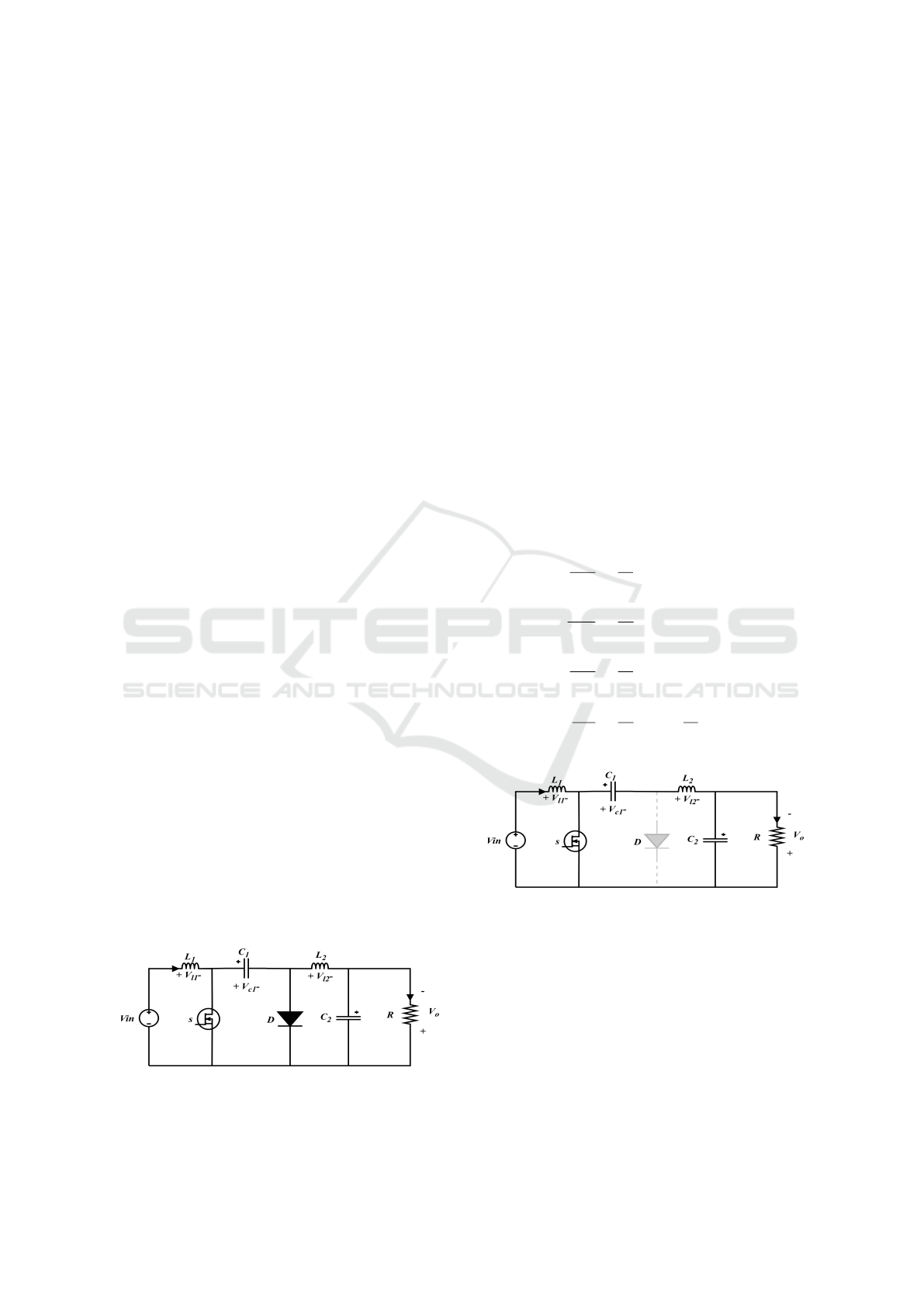
(Mumtaz et al., 2021). CUK converters, which con-
sist of two inductors and two capacitances, are a
type of fourth-order DC-DC converter. CUK convert-
ers are circuit topologies that transfer the DC volt-
age level applied to the input to a higher or lower
level to the output by appropriate control methods
(Narayanaswamy and Mandava, 2023). CUK con-
verters have an output voltage in the opposite polarity
of the input voltage (Singh, 2017).
Figure 1: Cuk converter topology.
CUK converters are obtained by cascading the
Boost converter and Buck converter topologies. For
this reason, they have the ability to both increase and
decrease the input voltage. The most important ad-
vantage of these converters is the presence of induc-
tance at the input and output of the circuit. In this
way, current fluctuations are reduced to a minimum
level. The visual of the CUK converter topology is
presented in Figure 1.
The CUK converter topology operates in two op-
erating modes, Pulse Width Modulation (PWM) ris-
ing edge and falling edge triggering. When the MOS-
FET is triggered by the rising edge, the inductance
L
1
is energized by the source voltage V
i
n and the en-
ergy is stored as a magnetic field. Capacitor C
2
is
discharged to ground through the MOSFET and en-
ergizes inductor L
2
and the load, the diode exhibits
open circuit characteristics. The electrical equivalent
circuit of the CUK converter MOSFET on mode is
shown in Figure 2. The mathematical equations for
this case are given in Equation (1) (Yılmaz et al.,
2020).
di
L
1
dt
=
1
L
1
(V
in
−V
c
1
)
dV
c
1
dt
=
1
C
1
i
L
1
di
L
2
dt
=
1
L
2
(−V
0
)
dV
0
dt
=
1
C
2
i
L
2
−
V
0
R
(1)
Figure 2: Switching element conduction state CUK con-
verter circuit topology.
When the MOSFET low pulse is triggered, the
energy stored in inductor L
1
is transferred to capac-
itor C
1
and indirectly in inductor L
2
. The diode is
in on mode for this situation. Energy is supplied to
the load through inductor L
2
.The electrical equivalent
circuit of the CUK converter MOSFET cut-off mode
is shown in Figure 3. The mathematical equations
for this case are given in Equation (2) (Yılmaz et al.,
2020).
ICEEECS 2025 - International Conference on Advances in Electrical, Electronics, Energy, and Computer Sciences
148
di
L
1
dt
=
1
L
1
(V
in
−V
c
1
)
dV
c
1
dt
=
1
C
1
i
L
1
di
L
2
dt
=
1
L
2
(−V
0
)
dV
0
dt
=
1
C
2
i
L
2
−
V
0
R
(2)
Figure 3: Switching element cut-off status CUK converter
circuit topology.
Table 1 gives the mathematical expressions of the
electrical circuit parameters of the CUK converter
topology used in the study.
Table 1: Mathematical expressions of electrical circuit pa-
rameters of CUK converter topology.
Parameter Formula
Duty Cycle D =
|V
in
|
V
S
+|V
in
|
Inductance L
1
=
DV
S
∆i
L
1
f
S
L
2
=
DV
S
∆i
L
2
f
S
Capacitance C
1
=
DV
in
∆V
C
1
R f
S
C
2
=
D − 1
8
∆V
in
V
in
f
2
S
Load R
Switching Frequency f
S
2.2 High Order Sliding Mode Control
Higher order sliding mode control (HOSMC) is a con-
trol method developed from Sliding Mode Control
(SMC). It is used to provide simplicity, high perfor-
mance, stability and vibration reduction to nonlinear
systems. HOSMC includes tracking calculation, shift
calculation and supertwist calculation. Its advantages
over sliding mode controllers are that it is more ro-
bust against the uncertain behaviour of the system and
provides faster response and provides superior perfor-
mance by preventing the system from vibration. The
mathematical expressions used for HOSMC are given
in Equations 3-6 (Yılmaz and C¸ orapsız, 2025).
u
1
(t) = λ
1
p
|S|sign(S) (3)
u
2
(t) = λ
2
Z
sign(S)dt (4)
u
3
(t) = λ
3
sign(S) (5)
u(t) = λ
1
p
|S|sign(S) + λ
2
Z
sign(S)dt + λ
3
sign(S)
(6)
In Equation 3, it pulls the system quickly to the
sliding surface. It provides terminal attraction be-
haviour. In Equation 4, it is added so that the system
does not make permanent errors. It is known as inte-
gral sliding mode control and is more resistant to dis-
turbances. In Equation 5, it pulls the system quickly
to the sliding surface but can cause unwanted vibra-
tions called flutter. In Equations 3-6,λ
1
, λ
2
,λ
3
the
coefficients that provide the balance between conver-
gence speed, steady-state accuracy, and jitter reduc-
tion.
3 RESULTS AND DISCUSSION
In this study, the dynamic performance of the CUK
converter is evaluated using HOSMC and PI con-
troller. The dynamic performance of the CUK con-
verter is evaluated in detail for four different scenar-
ios. Considering the increase/decrease of the output
voltage, important performance criteria such as effi-
ciency and settling time are analysed.
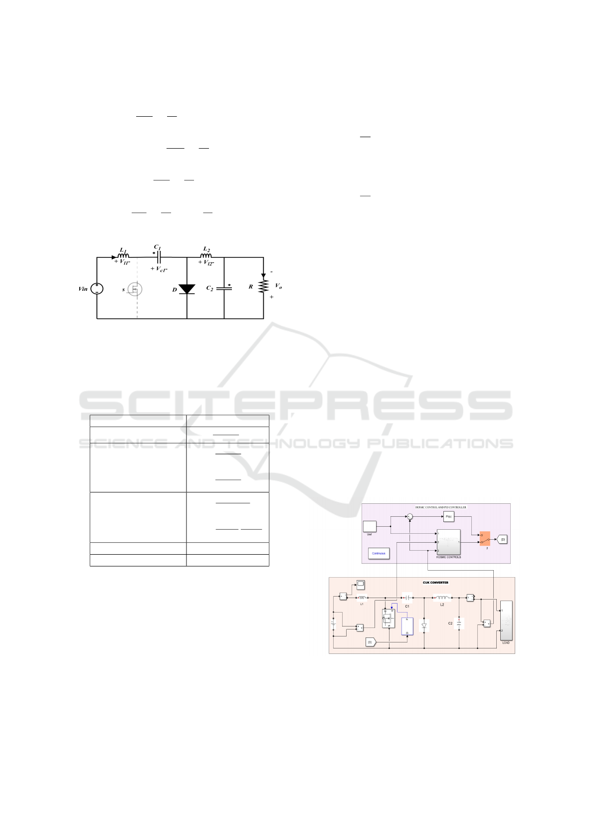
Figure 4: Simulation model of the CUK converter with PI
control and HOSMC.
The parameters of the CUK converter used
in the simulation studies are; capacitors C
1
=
12.35 µF, C
2
= 10.42 µF, inductors L
1
= 800 µH
High Order Sliding Mode Control for Power Regulation: Comparative Insights with PI Controller CUK Converter Implementation
149
ve L
2
= 1600 µH and load R = 36 Ω The output volt-
age of the CUK converter is -60V in the first scenario,
and -45V, -15V in the third scenario, first in the fourth
scenario1.5per second-60V and next 1.5 per second
-45V. Figure 4 shows the CUK converter designed
in MATLAB/SIMULINK 2021b to evaluate the per-
formance of the controllers under different scenarios.
The input voltage for all scenarios is 30V was taken
as fixed.
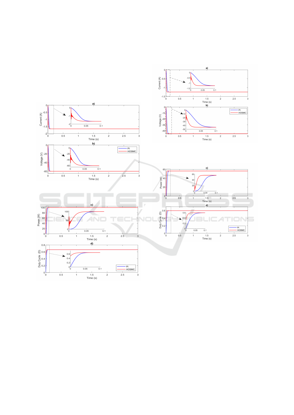
Figure 5: Load a) current-time b) voltage-time changes for
the first scenario.
Figure 6: Load a) power-time b) duty cycle-time variations
for the first scenario.
In the first scenario, the input voltage is reverse
polarity. 60 VDC voltage. In this scenario, the PI
controller and HOSMC’s ability to increase the input
voltage by two times was evaluated. According to the
HOSMC PI controller, the duty cycles 0.04 It was ob-
served that the output voltage reached its steady state
by finding the best value in seconds. 0.01% tolerant
-60 DC nominal voltage is fixed, and energy conver-
sion efficiency is measured as 100%. Figure 5 shows
the changes in load current and voltage with respect to
time. Figure 6 shows the changes in power and duty
cycle with respect to time.
Figure 7: Load a) current-time b) voltage-time changes for
the second scenario.
Figure 8: Load a) power-time b) duty cycle-time variations
for the second scenario.
In the second scenario, the voltage boost perfor-
mance of the controllers 30 V In this scenario, the
system’s transient behavior and steady-state perfor-
mance were observed. According to the PI controller,
the most optimum value of the HOSMC duty cycle
was 0.03 seconds and reached its steady state. Out-
put voltage %0, 01 tolerant −45V DC voltage value
was reached and energy conversion efficiency was ob-
tained as 100%. The changes of load current and volt-
age with respect to time are given in Figure 7. The
changes of power and duty cycle with respect to time
are shown in Figure 8.
In the third scenario, the performance of HOSMC
and PI controllers in reducing the input voltage level
by half is examined. While HOSMC reaches the most
optimum value of the duty cycle in 0.05 seconds, PI
controller reaches the most optimum value of the duty
ICEEECS 2025 - International Conference on Advances in Electrical, Electronics, Energy, and Computer Sciences
150
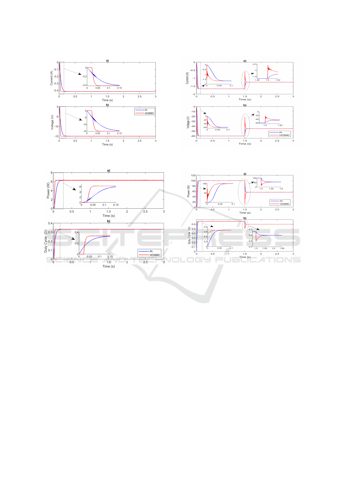
Figure 9: Load a) current-time b) voltage-time changes for
the third scenario.
Figure 10: Load a) current-time b) voltage-time changes for
the third scenario.
cycle in 0.15 seconds. HOSMC control structure not
only reaches the optimum duty cycle in a shorter time
to ensure the stability of the system, but also exhibits
superior performance in transient behaviors. In par-
ticular, the fact that the duty cycle becomes stable in
only 0.05 seconds reveals the fast response ability of
the system. The changes in the load current and volt-
age values with respect to time are given in Figure
9, and the changes in the power and duty cycle with
respect to time are given in Figure 10.
In the fourth scenario, the performances of the PI
controller and HOSMC were evaluated for different
voltage levels in different time periods. The input
voltage was increased from 30V to 60V for the first
1.5 seconds. The voltage value of 60V was decreased
to 45V for the next 1.5 seconds. For this scenario, it
was observed that the HOSMC had a shorter settling
time compared to the PI controller in the first 1.5 sec-
onds. The results of this scenario are shown in Figure
11 and Figure 12.
Figure 11: Load a) current-time b) voltage-time changes for
the second scenario.
Figure 12: Load a) power-time b) duty cycle-time variations
for the second scenario.
4 CONCLUSIONS
In this study, the dynamic behavior of PI controller
and HOSMC in CUK converter is comparatively an-
alyzed in terms of current, voltage, power and duty
cycle. Four different scenarios are evaluated in the
study. In all scenarios, HOSMC exhibits shorter con-
vergence time capability compared to PI controller.
In the first two scenarios, the voltage boost feature
of CUK converter is evaluated, and in the third sce-
nario, the voltage reduction feature. In the fourth
scenario, the desired output voltage sudden change is
evaluated. In all scenarios, HOSMC and PI controller
reach 100% efficiency. HOSMC exhibits strong re-
sistance by behaving more robustly against uncertain-
ties and external disturbances in the system. In addi-
tion, it has the advantages of faster transient response,
lower overshoot and shorter settling time thanks to its
high-order derivative feedback structure. HOSMC’s
discrete-time operating structure and high accuracy
High Order Sliding Mode Control for Power Regulation: Comparative Insights with PI Controller CUK Converter Implementation
151

enable it to provide superior control performance es-
pecially in nonlinear and parameter-variable systems.
With these aspects, HOSMC gave more successful re-
sults than the PI controller in terms of both control
quality and system reliability
ACKNOWLEDGEMENTS
This work was supported by the Atat
¨
urk Univer-
sity Coordination Unit of Scientific Research Projects
(Project No: FBA-2025-15043)
REFERENCES
Balestrino, A., Landi, A., and Sani, L. (2002). Cuk con-
verter global control via fuzzy logic and scaling fac-
tors. IEEE Transactions on Industry Applications,
38(2):406–413.
Chen, Z. (2012). Pi and sliding mode control of a cuk
converter. IEEE Transactions on Power Electronics,
27(8):3695–3703.
Fathabadi, H. (2016). Novel high efficiency dc/dc boost
converter for using in photovoltaic systems. Solar En-
ergy, 125:22–31.
Ilman, S. M., Dahono, A., Prihambodo, M. A. K., Putra,
B. A. Y., Rizqiawan, A., and Dahono, P. A. (2019).
Analysis and control of modified dc-dc cuk converter.
In Proc. 2nd Int. Conf. High Voltage Engineering and
Power Systems (ICHVEPS).
Mahho, M., Yilmaz, M., and C¸ orapsiz, M. F. (2025). The
performance of modified sepic converter for dynamic
conditions with pi controller. In 2025 7th Inter-
national Congress on Human-Computer Interaction,
Optimization and Robotic Applications (ICHORA),
pages 1–4.
Mumtaz, F., Yahaya, N. Z., Meraj, S. T., Singh, B., Kannan,
R., and Ibrahim, O. (2021). Review on non-isolated
dc-dc converters and their control techniques for re-
newable energy applications. Ain Shams Engineering
Journal, 12(4):3747–3763.
Narayanaswamy, J. and Mandava, S. (2023). Non-isolated
multiport converter for renewable energy sources: A
comprehensive review. Energies, 16(4):1834.
Refaat, A., Elbaz, A., Khalifa, A.-E., Elsakka, M. M.,
Kalas, A., and Elfar, M. H. (2024). Performance eval-
uation of a novel self-tuning particle swarm optimiza-
tion algorithm-based maximum power point tracker
for proton exchange membrane fuel cells under dif-
ferent operating conditions. Energy Conversion and
Management, 301:118014.
Singh, S. (2017). Selection of non-isolated dc-dc converters
for solar photovoltaic system. Renewable and Sustain-
able Energy Reviews, 76:1230–1247.
Xu, L., Guerrero, J. M., Lashab, A., Wei, B., Bazmo-
hammadi, N., Vasquez, J. C., and Abusorrah, A.
(2021). A review of dc shipboard microgrids—part i:
Power architectures, energy storage, and power con-
verters. IEEE Transactions on Power Electronics,
37(5):5155–5172.
Yılmaz, M., Corapsiz, M., and C¸ orapsız, M. R. (2020).
Voltage control of cuk converter with pi and fuzzy
logic controller in continuous current mode. Balkan
Journal of Electrical and Computer Engineering,
8(2):127–134.
Yılmaz, M. and C¸ orapsız, M. F. (2025). A robust mppt
method based on optimizable gaussian process regres-
sion and high order sliding mode control for solar sys-
tems under partial shading conditions. Renewable En-
ergy, 239:122339.
Yılmaz, M., C¸ orapsız, M. R., and C¸ orapsız, M. F. (2025). A
novel maximum power point tracking approach based
on fuzzy logic control and optimizable gaussian pro-
cess regression for solar systems under complex envi-
ronment conditions. Engineering Applications of Ar-
tificial Intelligence, 141:109780.
ICEEECS 2025 - International Conference on Advances in Electrical, Electronics, Energy, and Computer Sciences
152
