
Design and Validation of Sensorized Tools for Deformable Object
Manipulation in Meat Cutting and Doll Demoulding
Saltanat Seitzhan
1 a
, Dionisio Cartagena Gonz
´
alez
2 b
, Alexis Babut
3 c
,
Daniel S
´
anchez-Mart
´
ınez
2 d
, Juan Antonio Mic
´
o
2
, Chedli Bouzgarrou
3 e
and Juan Antonio Corrales Ram
´
on
1 f
1
Universidade de Santiago de Compostela, Santiago de Compostela, Spain
2
AIJU Technological Institute for Children’s Products and Leisure, Alicante, Spain
3
Universit
´
e Clermont Auvergne, Clermont Auvergne INP, CNRS, Institut Pascal F-63000 Clermont-Ferrand, France
Keywords:
Sensorized Tools, Soft Robotics, Demoulding, Meat Cutting, Force Sensing, Learning by Demonstration,
Collaborative Robots, Automation.
Abstract:
While robotic arms are extensively deployed in mass production environments, their application in tasks in-
volving deformable object manipulation remains limited due to the complex dynamics of soft materials. Ad-
dressing this challenge requires task-specific end-effector tools capable of replicating manual operations with
precision and adaptability. Standard human tools are often incompatible with robotic systems, especially in
domains such as meat processing and doll manufacturing. This study presents the design and experimental
validation of sensor-integrated end-effectors tailored for deformable object handling: a knife tool for robotic-
assisted meat cutting and a plier tool for analyzing the demoulding process in doll production. Both tools
incorporate multimodal sensing, including force/torque sensors and inertial measurement units, and are syn-
chronized via ROS to capture manipulation data under realistic conditions. While full cobotic manipulation
and Learning from Demonstration (LfD) are reserved for future work, the results demonstrate the feasibility
of embedding sensing into manual and robotic tools to support future automation in soft material handling.
1 INTRODUCTION
The manipulation of deformable objects poses persis-
tent challenges in robotics due to the unpredictable
and nonlinear behavior of soft materials. While au-
tomation has made significant strides in rigid object
handling, tasks involving soft components such as
cutting, gripping, or assembly remain largely depen-
dent on human expertise. This limitation is particu-
larly evident in industrial domains like meat process-
ing and toy manufacturing, where the complexity of
soft object interactions continues to hinder full au-
tomation.
In the meat industry, for example, the irregularity
a
https://orcid.org/0009-0002-0620-9617
b
https://orcid.org/0009-0003-3060-7815
c
https://orcid.org/0009-0005-2749-1422
d
https://orcid.org/0009-0008-2279-3503
e
https://orcid.org/0000-0003-2394-1770
f
https://orcid.org/0000-0002-9373-7954
of meat pieces has led to the adoption of robotic as-
sistance rather than full automation for cutting tasks.
Despite advances in sensing and modeling, the vari-
ability in tissue structure, fat distribution, and car-
cass geometry makes it difficult to generalize cutting
strategies across specimens. Robotic systems have
been deployed for tasks such as primal cutting and
trimming, often relying on preoperative scanning or
vision-based guidance (Aly et al., 2023; Mason et al.,
2022). However, full automation remains elusive, and
collaborative approaches, such as human-in-the-loop
systems or sensorized tools, are increasingly explored
to capture expert manipulation strategies (Maithani
et al., 2021).
Similarly, in doll production, processes like de-
moulding and assembly of vinyl parts are still per-
formed manually due to the complexity of soft ob-
ject interactions. Recent efforts have explored au-
tomation in these domains, with varying degrees of
success. In toy manufacturing, collaborative robotic
552
Seitzhan, S., González, D. C., Babut, A., Sánchez-Martínez, D., Micó, J. A., Bouzgarrou, C. and Corrales Ramón, J. A.
Design and Validation of Sensorized Tools for Deformable Object Manipulation in Meat Cutting and Doll Demoulding.
DOI: 10.5220/0013967900003982
Paper published under CC license (CC BY-NC-ND 4.0)
In Proceedings of the 22nd International Conference on Informatics in Control, Automation and Robotics (ICINCO 2025) - Volume 2, pages 552-565
ISBN: 978-989-758-770-2; ISSN: 2184-2809
Proceedings Copyright © 2025 by SCITEPRESS – Science and Technology Publications, Lda.

systems have been deployed to automate demould-
ing tasks using vision-guided manipulation and cus-
tom grippers with embedded force control (S
´
anchez-
Mart
´
ınez et al., 2023). In parallel, research in robotic
learning has demonstrated the potential of sensorized
tools to capture human manipulation strategies, par-
ticularly within Learning from Demonstration (LfD)
frameworks (Song et al., 2022; Zakaria et al., 2022).
These tools enable the recording of multimodal data
including force, motion, and orientation under realis-
tic working conditions, facilitating the transfer of hu-
man skills to robotic platforms.
This paper builds upon these developments and
proposes two fully embedded sensorized handheld
tools. Firstly, a sensor-implemented knife end-
effector series with different variations of sensor
placement along with tactile-sensitive handle. Sec-
ondly, a sensor-implemented plier tool designed to
capture human demonstrations during soft object ma-
nipulation. The remainder of this paper is organized
as follows: Section 2 reviews related work; Section 3
describes the tool design and instrumentation; Sec-
tion 4 presents experimental validation; and Section 6
concludes the paper. The key contributions of this
work are as follows:
• Design of sensorized end-effectors tailored for de-
formable object manipulation in industrial con-
texts, specifically meat cutting and doll demould-
ing.
• Integration of multimodal sensing (force, orien-
tation, tactile pressure) into ergonomic handheld
tools to capture human demonstrations without
disrupting natural behavior.
2 BACKGROUND
2.1 Meat Cutting
The automation of meat processing presents a so-
lution to address persistent challenges in labor-
intensive, hazardous, and hygiene-sensitive environ-
ments. The red meat industry, particularly in cutting
and deboning operations, is characterized by repet-
itive tasks, exposure to cold temperatures, and high
injury rates, making it a prime candidate for robotic
intervention (Aly et al., 2023).
Earlier work by Choi et al. (Choi et al., 2013)
highlighted the potential of industrial robots to allevi-
ate ergonomic strain and improve consistency in meat
processing. Their study emphasized the importance
of integrating force control and vision systems to nav-
igate the variability inherent in carcass morphology.
However, the complexity of handling deformable bi-
ological materials such as muscle, fat, and connective
tissue has limited the adoption of robotic systems be-
yond simple, rigid tasks.
Recent advances have focused on enhancing
robotic perception and adaptability. Aly et al. (Aly
et al., 2023) provided a comprehensive review of
sensing technologies in red meat processing, iden-
tifying X-ray, ultrasonic, optical probes, and tac-
tile sensing as key enablers for trajectory planning
and adaptive control. Their analysis underscored the
limitations of preoperative scanning alone and advo-
cated for hybrid systems combining real-time feed-
back with anatomical modeling.
In parallel, the RoBUTCHER project intro-
duced the concept of the Meat Factory Cell
(MFC), a modular robotic platform designed for
hot boning and autonomous disassembly of pig car-
casses (de Medeiros Esper et al., 2021). This system
leverages RGB-D vision, computed tomography, and
machine learning to plan and execute cuts, while ad-
dressing hygiene and scalability concerns. Building
on this, Mason et al. (Mason et al., 2022) developed
a smart knife equipped with electromagnetic sensing,
capable of detecting contact and cutting depth with
high precision. This tool demonstrated the feasibil-
ity of integrating sensorized end-effectors into robotic
workflows, enabling real-time feedback and adaptive
control.
Complementary studies have investigated robotic
manipulation of deformable objects using mass-
spring models, structured light, and force feed-
back (Long et al., 2014a; Long et al., 2014b; Nabil
et al., 2015). These approaches aim to simulate tissue
behavior and inform control strategies, though chal-
lenges remain in achieving real-time responsiveness
and generalization across carcass types.
Our previous work on Exoscarne (Maithani et al.,
2021) explored human-robot collaboration in meat
cutting, proposing assistive strategies that com-
bine physical human-robot interaction with trajectory
guidance. By leveraging the operator’s expertise and
tactile perception, Exoscarne reduced cutting effort
and improved safety, laying the groundwork for semi-
autonomous systems in complex tasks. The current
study builds upon this progress by introducing reac-
tive, friction-reducing features in the robotic cutting
tool.
2.2 Doll Industry Automation
The automation of manual tasks involving complex
interaction with deformable objects remains a sig-
nificant challenge in industrial robotics. Captur-
Design and Validation of Sensorized Tools for Deformable Object Manipulation in Meat Cutting and Doll Demoulding
553
ing and transferring a human operator’s manipula-
tion strategy to a collaborative robot requires sen-
sorized tools capable of recording both trajectories
and applied forces. Several studies have addressed
this through Learning from Demonstration (LfD), of-
ten relying on external sensors like motion capture or
wrist-mounted force/torque sensors, which limit real-
world applicability due to occlusion and calibration
issues. The SoftManBot project demonstrated the
feasibility of using task-specific sensorized tools for
soft object handling in toy manufacturing (S
´
anchez-
Mart
´
ınez et al., 2023). However, early prototypes
lacked embedded force sensing. Recent work has ad-
vanced this by integrating tactile arrays (Song et al.,
2022) and inline force sensing (Zakaria et al., 2022),
enabling dynamic grasp evaluation and DRL-based
control of soft linear objects. Building on these in-
sights, we propose a fully embedded, multimodal sen-
sorized tool for capturing human demonstrations un-
der real working conditions.
3 DESIGN OF THE SENSORIZED
TOOLS
3.1 Knife End-Effector for Meat
Cutting
This section presents the development of the in-
strumented tool mounted on the robot’s tool flange
(UR30), with a focus on its mechanical integration
and force/torque (F/T) sensing capabilities. The tool
is designed to accurately perceive contact between the
human operator and the manipulated object during
task execution.
Another key design consideration was to closely
replicate the tools commonly used in the meat-cutting
industry. Thus, the distance between the knife handle
and the blade was minimised to prevent the operator
from experiencing an unnatural sensation caused by
an excessively long gap relative to the handle.
3.1.1 Sensor Integration at the Robot Tool
Flange
To enable reliable force sensing, an F/T sensor is
mounted on the tool flange of the UR30 collaborative
robot. Two main sensor models have been used de-
pending on the setup: either the BOTA Systems Sen-
sONE T15 or the BOTA Systems SensONE T80. The
choice of sensor depends on the specific requirements
and mechanical constraints of each experimental con-
figuration.
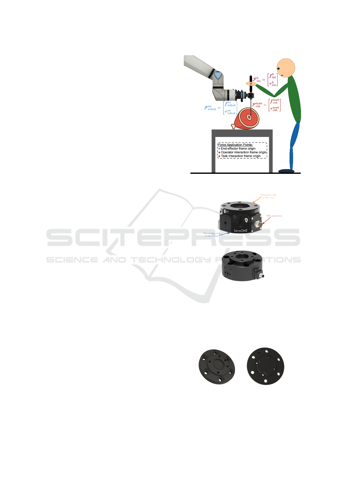
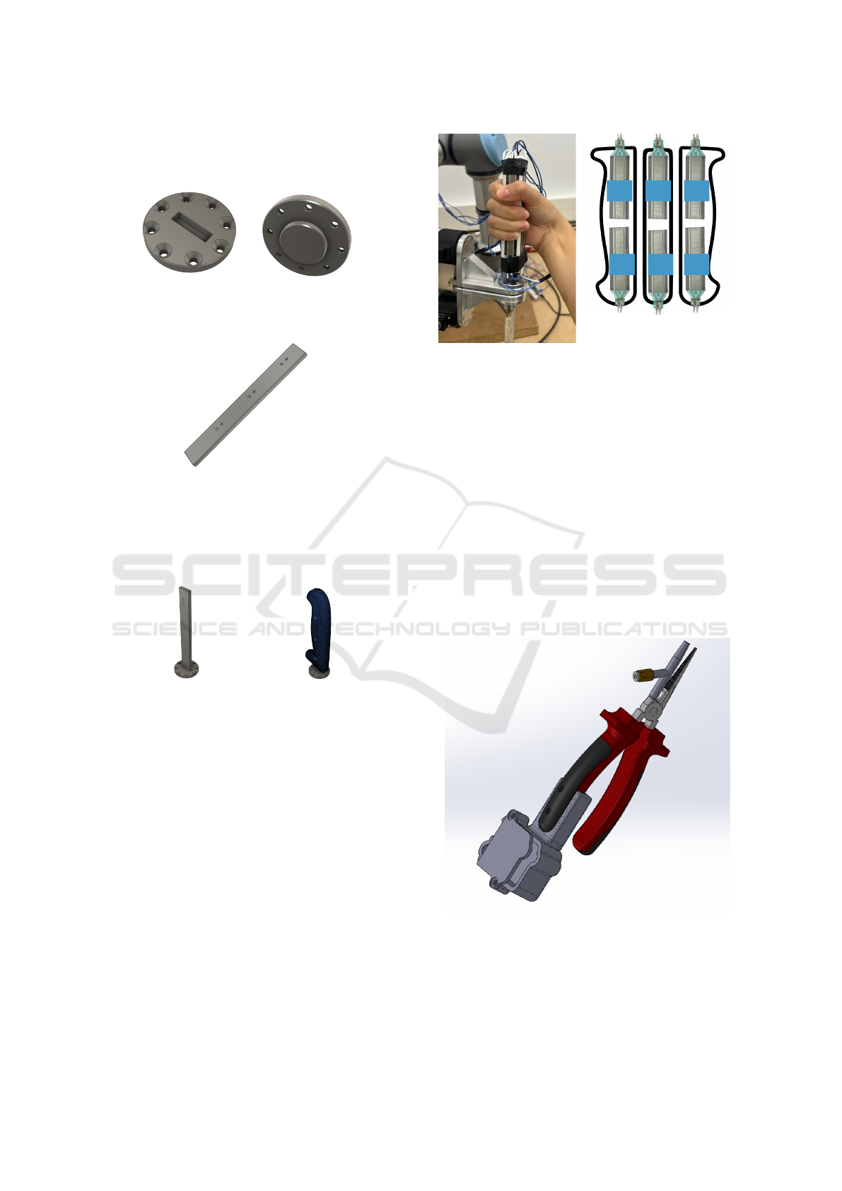
Figure 1: Forces applied on the tool during a meat-cutting
task with a robot.
(a) SensONE T15
(b) SensONE T80
Figure 2: BOTA Systems SensONE sensors.
The SensONE T80 sensor is directly compatible
with the UR30 flange, while the T15 requires a cus-
tom mechanical adapter. This adapter, manufactured
by FDM (Fused Deposition Modeling) 3D printing in
PA-CF (Nylon reinforced with carbon fibre), ensures
proper sensor integration.
(a) Sensor side (b) Robot side
Figure 3: PA-CF adapter for the SensONE T15 sensor.
Since the tool is subjected to forces from both the
operator and the cutting interaction, a single sensor
COBOTA 2025 - Special Session on Bridging the Gap in COllaborative roBOtics: from Theory to real Applications
554
cannot distinguish between them. To address this, a
second sensor (BOTA Systems Rokubi) is added to
isolate and measure these forces independently. This
also opens the possibility to prototype a design in-
corporating two additional Rokubi sensors, adding re-
dundancy and enabling direct measurement of cutting
and operator-applied forces. Two main configurations
were developed for the knife prototype at the end-
effector, each positioned after the primary F/T sensor.
3.1.2 Single-Sensor Configuration for Force
Isolation
A single Rokubi sensor is integrated to directly mea-
sure either the forces applied by the operator or those
resulting from interaction with the task. The Sen-
sONE sensor continues to measure the overall force
data and the main sensor is used to estimate the cut-
ting forces. This approach requires an accurate evalu-
ation of the tool’s weight and centre of mass to ensure
correct force estimation.
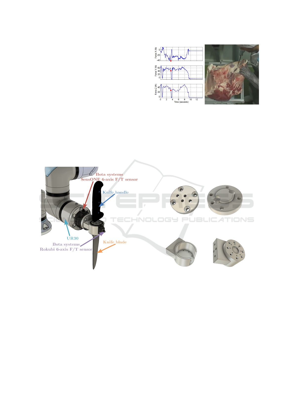
Figure 4: Knife prototype with one additional F/T sensor.
As the forces involved in the cutting task do not
exceed a maximum of 200 N, as confirmed by a pre-
vious force evaluation shown in Figure 5, three pro-
totypes with identical dimensions and geometry were
developed. One prototype was machined from alu-
minium 5083, another was manufactured using FDM
3D printing with polyamide PA12, and the third was
produced using FDM 3D printing with PA-CF, a
polyamide reinforced with short carbon fibres. These
material variants enable a comparative assessment of
stiffness, durability, and overall mechanical perfor-
mance during meat-cutting operations.
Figure 5: Forces applied during a manual anatomical meat-
cutting task.
Metallic Design
In this version, a Rokubi sensor is placed between the
main SensONE sensor and the knife. The mounting
interface, composed of two machined aluminum parts
(or alternatively polyamide PA12 components), is de-
signed symmetrically to allow the entire assembly to
be mounted in two orientations. This reversible con-
figuration enables the measurement of either blade-
applied forces or handle-applied forces, depending on
which component is positioned on the sensor side.
(a) Top view (b) Bottom view
Figure 6: First part of the adapter.
(a) Top view (b) Bottom view
Figure 7: Second part of the adapter.
Both parts include holes for cylindrical alignment
dowels to ensure precise positioning between com-
ponents. Once aligned, the assembly is secured us-
ing screws inserted into threaded holes in the metallic
parts.
This design allows the sensor to be almost entirely
enclosed by the adapter walls, providing mechanical
protection and reducing the risk of unintended con-
tact. This minimises the likelihood of measurement
disturbances or potential sensor damage during oper-
ation.
Design and Validation of Sensorized Tools for Deformable Object Manipulation in Meat Cutting and Doll Demoulding
555
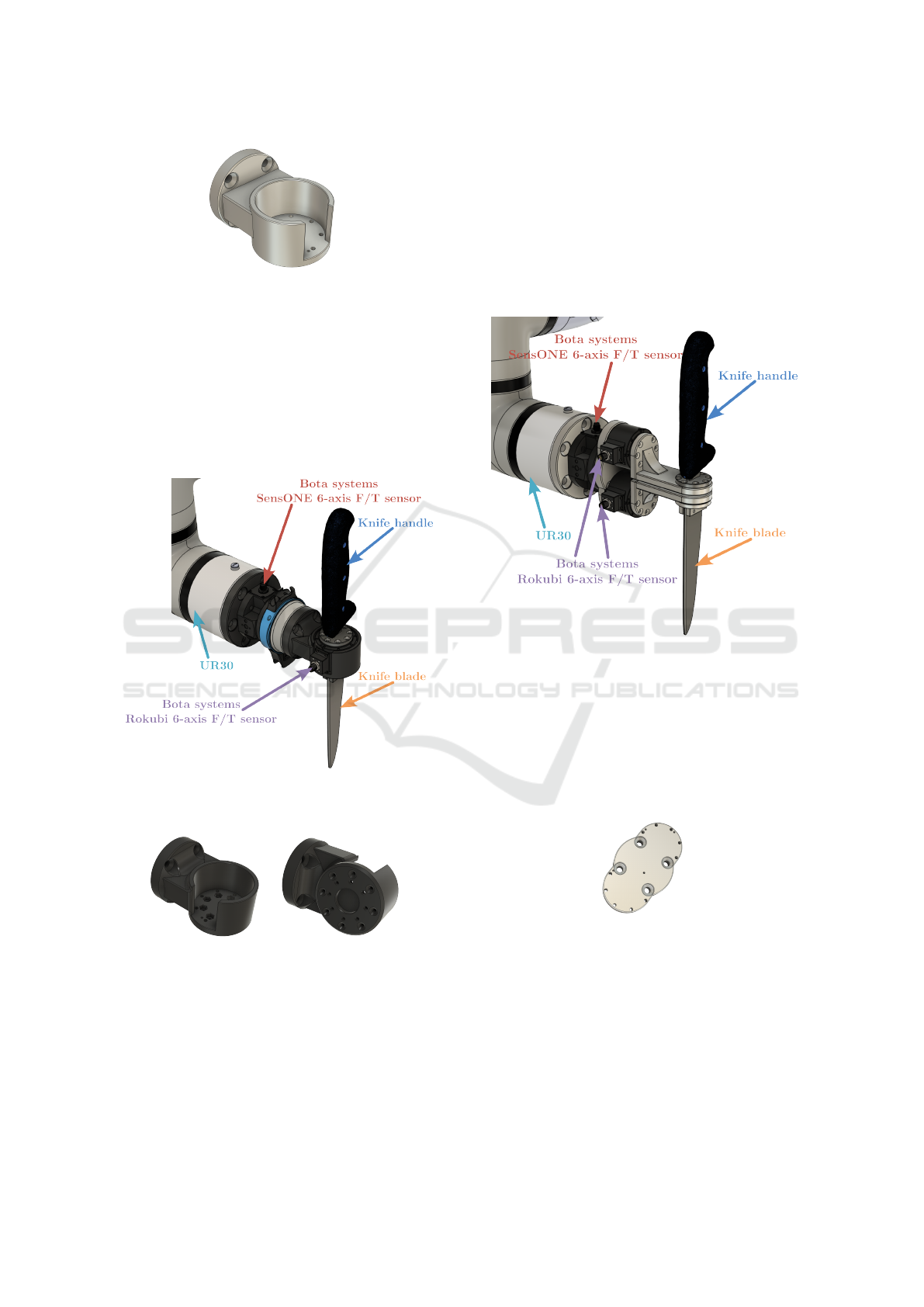
Figure 8: Fully assembled metallic adapter.
PA-CF Design
A functionally equivalent version was produced us-
ing PA-CF (polyamide reinforced with short carbon
fibers) to benefit from its favorable strength-to-weight
ratio and rigidity. This lighter design helps reduce the
static load on the robot, thereby maximizing the avail-
able force capacity for the task (the UR30 robot has a
payload limit of 30 kg).
Figure 9: Knife prototype with PA-CF version of the single-
sensor adapter.
(a) Top view (b) Bottom view
Figure 10: PA-CF single-sensor adapter views.
The component is made in one block and fol-
lows the same mechanical principles as the metallic
version. However, as it is not recommend to create
threaded holes in PA-CF, hexagonal recesses are in-
corporated to insert nuts, allowing the blade to be se-
curely fastened to the assembly.
3.1.3 Dual-Sensor Configuration for Force
Decoupling
This configuration integrates two Rokubi sensors to
simultaneously measure both cutting and operator-
applied forces. By directly capturing these two force
sources, the design improves measurement accuracy
and reduces the need for complex estimation or post-
processing.
Figure 11: Knife prototype with two additional force/torque
sensors.
The assembly consists of three machined alu-
minium components (Aluminium 5083): a central in-
terface connecting the main and additional sensors,
and two parts mounted on each Rokubi sensor. This
arrangement decreases the distance between the han-
dle and the blade compared to the single-sensor ver-
sion, improving ergonomics.
Figure 12: Central interface part connecting the two Rokubi
sensors with the main sensor.
The components connecting the Rokubi sensors to
the handle and the blade, as shown in Figure 13, con-
sist of three parts: the first mounts onto the Rokubi
sensor, the second attaches the measured component
(either the blade or the handle), and the third positions
and reinforces the overall assembly.
As previously described, threaded holes and cylin-
drical dowel pin holes are incorporated to ensure pre-
COBOTA 2025 - Special Session on Bridging the Gap in COllaborative roBOtics: from Theory to real Applications
556
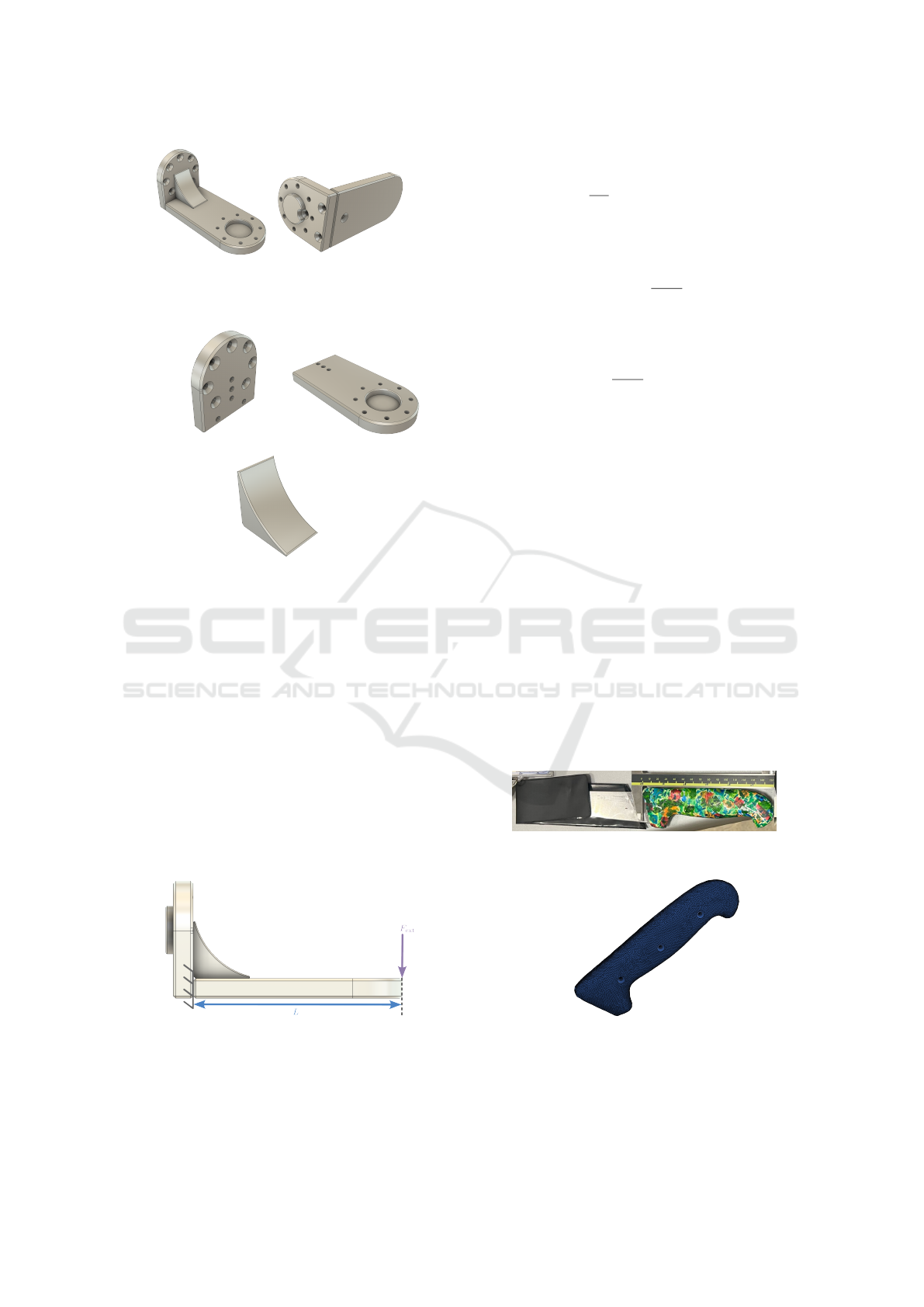
(a) Top view (b) Bottom view
Figure 13: Mounting components attached to the Rokubi
sensors.
(a) First part (b) Second part
(c) Third part
Figure 14: Three-part mounting structure.
cise alignment and secure assembly of all parts, in-
cluding the force sensors.
The second element, shown in Figure 14b, was de-
signed with a length of 84 mm to prevent any contact
between the user’s hand holding the handle and the
rest of the adapter. This clearance ensures ergonomic
handling while avoiding interference with the struc-
tural or sensor components during operation. To ver-
ify the structural integrity of this component, a sim-
plified beam deflection analysis was conducted. The
aluminium section is modelled as a cantilever beam
of length L, fixed at x = 0 and subjected to a vertical
force F
ext
= 200 N at the free end (x = L), as illustrated
in Figure 15.
Figure 15: Model used for structural deflection analysis of
the second adapter element.
The beam has a rectangular cross-section with
width b = 40 × 10
−3
m, height h = 8 × 10
−3
m, and
is made of Aluminium 5083 with a Young’s modulus
of E = 71 × 10
9
Pa. The second moment of area is
calculated as I =
b h
3
12
.
According to strength of materials theory, the ver-
tical deflection at any point x ∈ [0, L] under this load-
ing condition is given by:
v(x) =
F x
3
6 E I
Applied at the free end (x = L = 0.084 m), the ex-
pression becomes:
v(L) =
F L
3
6 E I
≈ 0.163 mm
This simulation confirms that under a representa-
tive cutting force of 200 N, the expected elastic de-
formation remains below 0.2 mm, ensuring that no
collision occurs between the upper and lower struc-
tural elements of the tool (see Figure 11), given the
2 mm clearance designed between the two compo-
nents. This mechanical stability prevents unintended
contact that could compromise measurement accu-
racy, while also minimising the distance between the
handle and the knife blade, which is essential for
maintaining an ergonomic tool geometry.
3.1.4 Knife Handle Prototypes
The knife handle was modelled from a 3D scan of a
real industrial knife, commonly used in meat process-
ing. This scan served as a realistic basis for designing
functional handle prototypes, which were manufac-
tured using PLA filament through FDM (Fused De-
position Modeling) 3D printing.
Figure 16: Industrial knife used as design reference.
Figure 17: PLA knife handle.
To ensure mechanical robustness, the PLA han-
dle is mounted onto a substructure made of welded
2085 steel, which serves as the internal support and
Design and Validation of Sensorized Tools for Deformable Object Manipulation in Meat Cutting and Doll Demoulding
557
structural backbone. This rigid interface ensures sta-
ble and repeatable performance during high-force cut-
ting tasks.
(a) Top side (b) Bottom side
Figure 18: First structural part supporting the handle.
Figure 19: Second part of the handle attachment.
Both steel parts are welded together to form a rigid
connector, as shown in Figure 20a. The final assem-
bled handle, integrating both the PLA outer shell and
the internal steel support, is presented in Figure 20b.
(a) Welded connector (b) Assembled handle
Figure 20: Knife handle prototype.
Sensitive Knife Handle
As previously mentioned, to predict the butcher’s in-
tentions and enable smooth re-orientation of the end-
effector without perceived friction, a sensitive knife
handle was prototyped. In the current setup (Fig-
ure 21), the handle is equipped with six off-the-shelf
tactile pressure sensors (Interlink FSR®).
3.2 Sensorized Plier for Doll
Demoulding
The primary objective of the design was to develop
a sensorized tool capable of capturing, during human
execution of the demoulding task, the three essential
variables required for robotic imitation: pulling force,
R1
R2
R6
R5
R3
R4
left middle right
Figure 21: Force Resistive Sensor placement on the handle.
3D orientation, and spatial trajectory. This data ac-
quisition had to be performed without interfering with
the operator’s natural movements and while meeting
ergonomic and mechanical robustness requirements
for a functional tool.
The development started from an experimental
tool used in the SoftManBot project, which was based
on a commercial pair of pliers fitted with an NGIMU
sensor encapsulated in a 3D-printed housing attached
to the end of one handle. This initial prototype en-
abled the recording of orientation and acceleration
but lacked force sensing and full access to raw sen-
sor data, limiting its usefulness for tasks requiring a
complete characterization of the physical interaction
during demoulding.
Figure 22: Starting point for tool design.
To overcome these limitations, a complete re-
design of the tool was undertaken using an itera-
tive approach. Various configurations of inertial sen-
sors were evaluated, including both commercial mod-
COBOTA 2025 - Special Session on Bridging the Gap in COllaborative roBOtics: from Theory to real Applications
558
ules and custom-built solutions. Ultimately, a high-
precision IMU composed of the ISM330DHCX sen-
sor and the MMC5983MA magnetometer was se-
lected. This choice was based on its high sampling
rate, excellent resolution, and low noise, enabling
a more accurate reconstruction of orientation during
the demoulding process. Unlike the previously used
NGIMU module, this solution provides direct access
to raw data, significantly reduces costs due to in-
house assembly, and offers greater flexibility for im-
plementing custom sensor fusion algorithms.
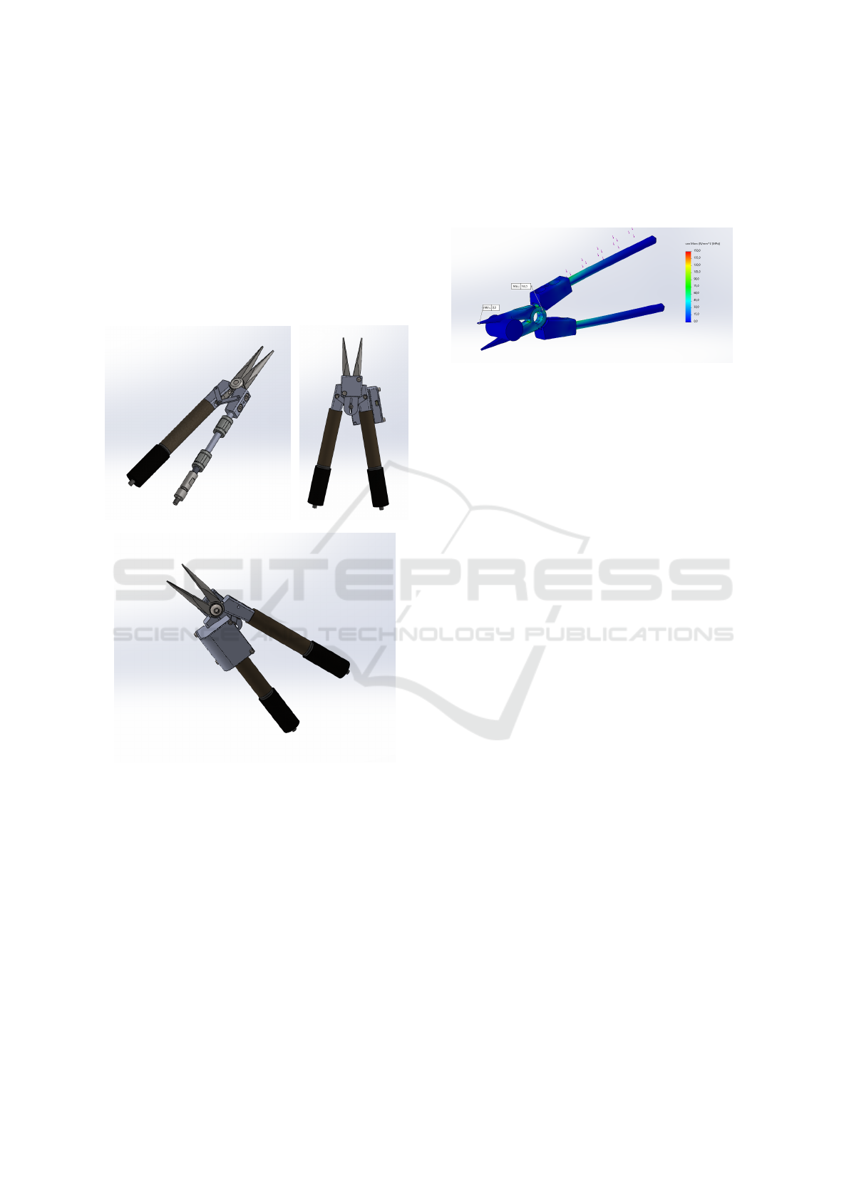
Figure 23: Current version of the tool at different stages of
assembly.
The redesign began with a CAD model, which was
subjected to finite element analysis (FEA) in Solid-
Works to validate its structural resistance under typ-
ical demoulding loads. An initial prototype was 3D-
printed to evaluate ergonomic aspects, sensor integra-
tion, and assembly feasibility. Following initial func-
tional testing, the final prototype was constructed us-
ing specific materials for each component function:
the head and jaws of the pliers were made from DIN
1.0401 (C15) steel, while the metallic handle frame
was fabricated from DIN 1.0503 (C45) steel. The
handle covers and housings for the force sensors were
3D-printed in PA12 polyamide, as were the casings
that house the IMU module, ESP32, ADC, and bat-
tery. Additionally, a custom part made of S275JR
steel was designed to keep the IMU centered at the
joint of the pliers, ensuring that the sensor remained
aligned with the bisector of the angle formed by the
handles during opening and closing.
Figure 24: Finite Element Analysis of the pliers.
This material distribution ensures mechanical ro-
bustness in load-bearing areas, lightweight construc-
tion in electronic integration zones, and geometric
stability for the sensor’s orientation, all while main-
taining an ergonomic and functional design suitable
for operator use.
3.2.1 Sensing and Integration Architecture
The final design of the tool integrates the following
components:
• Force Sensing: Two inline load cells (model
DYMH-106, 0–20kg), one in each handle, mea-
sure the pulling force applied by the operator. The
differential signals from both cells are electrically
combined to form a full Wheatstone bridge, which
is connected to a NAU7802 analog-to-digital con-
verter (ADC). This configuration provides a mea-
surement of the net pulling force exerted between
the two handles.
• Inertial Sensing: A 9-DoF IMU module
(ISM330DHCX + MMC5983MA) installed at the
pivot axis of the pliers records linear acceleration,
angular velocity, and the Earth’s magnetic field.
These data are fused using a Madgwick filter to re-
construct the full orientation of the system in real
time as Euler angles. The inclusion of the mag-
netometer is particularly important for correcting
yaw drift, enabling a stable heading estimate that
is critical for robotic imitation of human strate-
gies.
• Acquisition and Communication Unit: An
ESP32-S3 Zero manages data acquisition via I2C,
synchronizes all signals, and transmits the data in
real time to a ROS node over Wi-Fi. All electron-
ics, including the LiPo battery and boost converter
used to power the load cells, are integrated into
one of the handles.
Design and Validation of Sensorized Tools for Deformable Object Manipulation in Meat Cutting and Doll Demoulding
559
3.2.2 Sensor Calibration
IMU Calibration
In the final prototype, the NGIMU sensor was re-
placed with a more precise solution based on the
ISM330DHCX + MMC5983MA pair. This new
configuration improves both the resolution and the
sampling frequency of the inertial sensors. The
ISM330DHCX maintains the 16-bit resolution of the
accelerometer and gyroscope but increases the sam-
pling rate from 400Hz (in the NGIMU) to 833Hz, al-
lowing for more accurate capture of fast and transient
movements.
As for the magnetometer, the one used in NGIMU
offered a wider range (±1300µT), but with a resolu-
tion of only 0.3µT/LSB, an RMS noise of approxi-
mately 0.5–1µT, and a maximum acquisition rate of
20–75Hz. In contrast, the MMC5983MA provides a
range of ±800µT but achieves a resolution of up to
0.00625µT/LSB in 18-bit mode, total noise as low
as 0.04µT RMS, and an acquisition frequency of up
to 100Hz. These improvements enable a much more
accurate and stable estimation of the magnetic field,
which is particularly beneficial for correcting yaw
drift during sensor fusion. As a result, heading pre-
cision is significantly improved, reducing the orienta-
tion error from ±1 degree with the NGIMU to ±0.5
degrees with the new system.
In addition to improved performance, this new
setup provides better control over the acquired data,
the ability to automatically compensate thermal drifts,
reduced power consumption, and a significantly lower
unit cost, making it more suitable for embedded inte-
gration and scalable applications.
The gyroscope and accelerometer were manually
calibrated using a custom-made acrylic cube designed
to place the IMU in the six principal orientations
(±X, ±Y, ±Z). This approach allowed for determining
the static bias of each axis under well-defined rest-
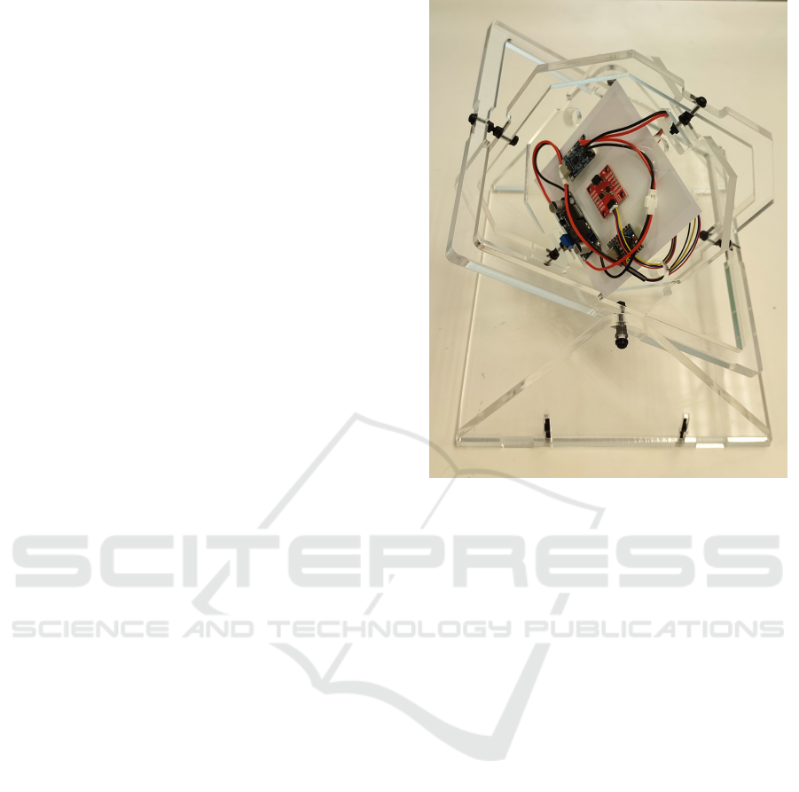
ing conditions. Regarding the magnetometer, its cal-
ibration was particularly critical to achieve accurate
yaw estimation, which is key to full orientation re-
construction during demoulding. For this purpose, a
yaw/pitch/roll calibration jig was built using acrylic
and nylon screws to avoid magnetic interference. In-
spired by the procedure described in (Heeb, 2008),
this device enabled controlled rotation along all three
axes, keeping the IMU at the center of the structure,
while the ESP32, charging system, and battery were
distributed around the jig in a layout similar to their
final arrangement in the tool, in order to replicate re-
alistic magnetic conditions during calibration.
During the calibration process, two types of mag-
netic distortions were identified and compensated:
Figure 25: Yaw/pitch/roll jig built for magnetic calibration.
• Hard Iron Distortion: caused by static magnetic
fields generated by nearby ferromagnetic materi-
als or permanent magnets, which shift the center
of the expected measurement sphere.
• Soft Iron Distortion: directional distortions
caused by conductive or magnetic materials near
the sensor, which deform the sphere into an ellip-
soid due to interaction with the Earth’s magnetic
field.
To correct these distortions, a geometric calibra-
tion was performed by fitting an ellipsoid to the 3D
data cloud obtained during a complete manual sweep.
This fitting allowed for the estimation of:
1. The ellipsoid center b = [x
c
, y
c
, z
c
]
T
, associated
with the hard iron effect.
2. The inverse transformation matrix A
−1
, which
corrects scaling factors and axis misalignments
(soft iron effect).
The general equation used to compute the cali-
brated reading h
c
from the measured magnetometer
data h
m
is:
h
c
= A
−1
· (h
m
− b) (1)
Where:
• h
m
∈ R
3
is the raw magnetometer reading,
• b is the bias vector (offset),
COBOTA 2025 - Special Session on Bridging the Gap in COllaborative roBOtics: from Theory to real Applications
560
• A
−1
is the inverse matrix that transforms the el-
lipsoid into a unit sphere. This matrix includes
scaling factors and possible minor rotations due
to non-orthogonal axis distortions.
The estimation of A and b is performed us-
ing a least-squares ellipsoid-specific fitting approach,
which minimizes the algebraic distance of the mea-
sured points to a general quadric surface under geo-
metric constraints. This method corresponds to case
k = 4 in the paper Least Squares Ellipsoid Specific
Fitting by Li and Griffiths [3] (Li and Griffiths, 2004).
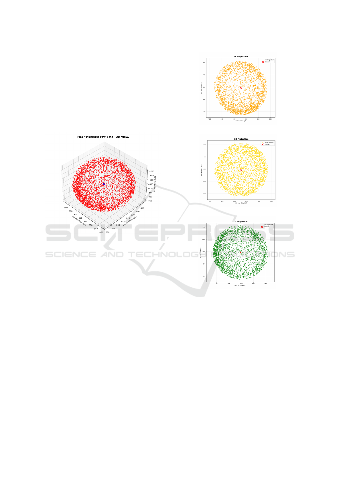
Figure 26: Magnetometer raw data (3D view).
Figure 26 shows the 3D representation of the point
cloud obtained during calibration. Figure 27 shows
the orthogonal projection on the XY, XZ, and YZ
planes, respectively.
After applying this calibration, an improvement
was observed in the uniformity of the magnetic field
magnitude, which is a strong indicator of effective
distortion compensation. The calibration process was
validated through 3D visualization and statistical met-
rics on the sphericity of the calibrated point cloud.
Load Cell Calibration
To characterize the load cells, a UR16e robot was
used in force control mode to apply controlled trac-
tion along the Z-axis on the sensorized tool, with
forces ranging from 0 to 200N. The forces were ap-
plied incrementally, and raw acquisition data were
captured for subsequent filtering and calibration.
The sensing system consists of two inline load
cells (model DYMH-106), each with a 20kg capac-
ity, a sensitivity of 0.8 ± 20%mV/V, and an accuracy
of 0.5% full scale (linearity + hysteresis + repeatabil-
ity). These cells provide differential output and fea-
ture IP67-rated enclosures. They are mounted inside
(a) XY projection
(b) XZ projection
(c) YZ projection
Figure 27: Projection of the point cloud on the main orthog-
onal planes.
the tool handles and connected electrically to form a
single Wheatstone bridge, which outputs a combined
force signal. Although the manufacturer recommends
an excitation voltage between 5 and 15V, in this ap-
plication all components are powered at 3.3V directly
from the ESP32-S3 Zero. Before considering the use
of a voltage booster and external ADC reference, the
system was tested at 3.3V with moderate gain, con-
firming linear behavior across the entire operational
range. Under these conditions, the expected maxi-
mum output from the differential SIG+/SIG– lines is
approximately 2.64mV, which falls within the sensi-
tivity range accepted by the NAU7802.
The Wheatstone bridge signal is acquired using
Design and Validation of Sensorized Tools for Deformable Object Manipulation in Meat Cutting and Doll Demoulding
561
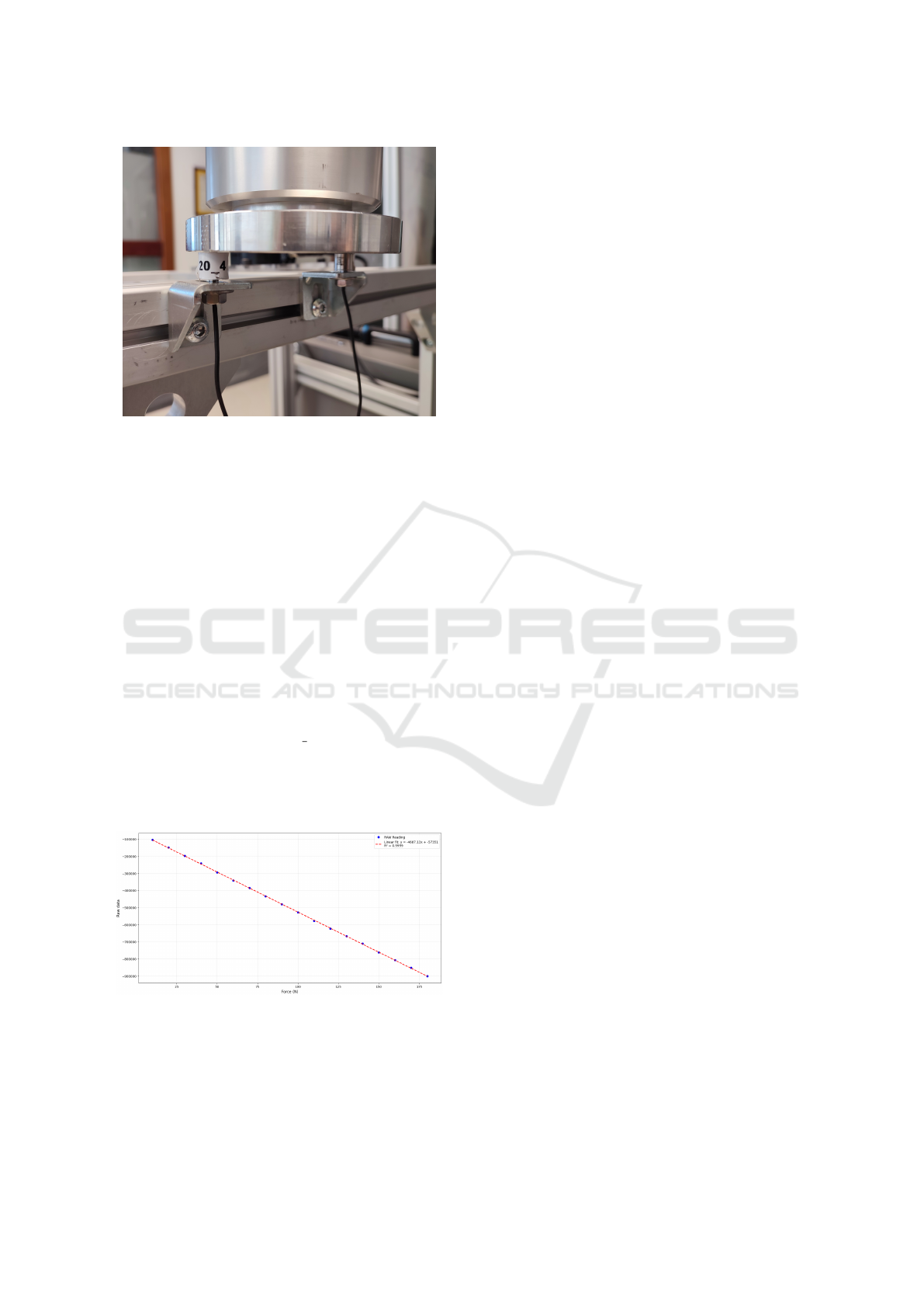
Figure 28: Calibration of load cells with the UR16e robot.
the NAU7802, a 24-bit ADC with an integrated am-
plifier specifically designed for load cell applications.
This device includes digital filtering to effectively
suppress 50Hz and 60Hz interference, which is com-
mon in industrial environments with power line noise.
To further reduce high-frequency noise, a sliding win-
dow averaging filter was implemented in firmware.
The window length is configurable, allowing for noise
attenuation without introducing significant measure-
ment delay.
During calibration, the raw data were fitted to a
linear curve using least squares, yielding the corre-
sponding scale factor (slope) and offset coefficients
for converting raw readings into force values ex-
pressed in Newtons:
Force(N) = m · Raw measure + b (2)
The analysis confirmed a strictly linear response
across the full operational range, with an average er-
ror of 0.64%, validating the suitability of both the sen-
sor and the signal conditioning system.
Figure 29: Load cells characterization representation.
Although the manufacturer specifies a thermal
drift of ±0.05% F.S./10°C in both offset and sensitiv-
ity, this effect is considered negligible under normal
working conditions. Nevertheless, the NAU7802 in-
cludes an internal temperature sensor, whose readings
are used in the firmware to apply automatic tempera-
ture compensation, thereby minimizing potential er-
rors caused by thermal variations during use.
3.2.3 Data Synchronization and Publishing
All sensors are connected to a single I2C bus in se-
ries configuration, managed by the ESP32-S3. Data
acquisition is performed at a constant frequency (up
to 100Hz), and readings are timestamped locally for
synchronization. The microcontroller transmits the
structured data packets via Wi-Fi to a ROS node on
an external PC. There, the data streams (force, IMU,
and visual position) are integrated into a unified time-
stamped structure for further analysis, visualization,
or use in learning algorithms.
4 EXPERIMENTAL VALIDATION
4.1 Evaluation of Cutting Forces for the
Knife End-effector
To evaluate the general force transmission during a
meat-cutting operation, a mock-up test was conducted
using a rigid fixture placed on top of a force sen-
sor to better observe the forces involved. The test-
ing setup included the end-effector prototype (Fig-
ure 11) equipped with two additional force sensors
(Botasys Rokubi), as shown in Figure 30. The knife
end-effector was mounted on a UR5e robotic arm,
which was controlled in Freedrive mode. A human
operator applied force along the y-axis in a back-and-
forth motion, as indicated in the same figure. A com-
parison between the applied force (at the handle side)
and the perceived force yielded a root mean square
error (RMSE) of 2.88 N.
To record the hand grip during the experiments,
six resistive tactile sensors were placed on the knife
handle. The readings from these sensors were trans-
formed into a color-coded tactile image for each time
instant, as demonstrated in Figure 32.
4.2 Evaluation of Demoulding Forces
for the Sensorized Plier
4.2.1 Orientation Validation via Comparison
with UR16e
To validate the accuracy of the inertial system, the
tool was mounted on the tool of a UR16e collabo-
rative robot and subjected to known translational and
rotational movements. The orientation readings (Eu-
ler angles) provided by the IMU were compared with
COBOTA 2025 - Special Session on Bridging the Gap in COllaborative roBOtics: from Theory to real Applications
562
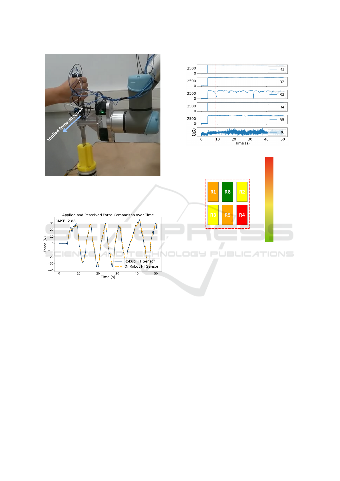
Figure 30: Force testing with the knife end-effector with
two additional force/torque sensors. The yellow plastic fix-
ture below is fixed on an OnRobot HEX-E force/torque sen-
sor which is taken as a measure of the ground truth of the
force applied by the knife blade.
Figure 31: Comparison of force measurements between the
Rokubi sensor integrated into the knife end-effector and the
HEX-E sensor positioned to receive force from the knife
blade. The RMSE between the two signals is 2.88 N, in-
dicating a close alignment between applied and perceived
forces.
the kinematic estimates generated by the UR Server
within the ROS environment.
The comparisons showed a close match between
both systems, with minor errors in the pitch and roll
axes and good yaw stability due to drift compensation
using the magnetometer. This validation confirms that
the system can provide reliable real-time orientation
estimates, even under transient accelerations.
4.2.2 Force Testing with Simulated Mold and
Bota Systems Sensor
To evaluate the dynamic response of the force sensors
during a realistic demoulding operation, a mockup
Tactile Sensors R1 to R6 over Time
(a)
9
Tactile Color code for the 9 second
th
(b)
High Pressure
Low Pressure
Figure 32: Six resistive tactile pressure sensors are attached
to the knife handle. In (a), the plots show the pressure val-
ues recorded during the experiments described in Figure 30.
To visualize the grip types and applied pressure, the sensor
readings were color-coded at each time instant, as shown in
(b). Preliminary tests are currently being conducted to pre-
dict the human operator’s intention by feeding these tactile
pressure images into neural networks.
was built using a doll part inserted into a simulated
mold. This setup was placed on a 6-axis force-torque
sensor from Bota Systems, capable of accurately mea-
suring forces (F
x
, F
y
, F
z
) and torques (M
x
, M
y
, M
z
) at
high frequency.
Manual extractions were performed using the sen-
sorized pliers while simultaneously recording:
• The forces applied to the tool via the integrated
load cells.
• The reaction forces within the part–mold system,
measured by the Bota sensor.
This dual measurement setup allowed for a quanti-
tative validation that the tool’s load cells correctly re-
flect the actual force exerted—both in magnitude and
direction. Clear correlations were observed between
the peaks of pulling force and the normal forces ex-
Design and Validation of Sensorized Tools for Deformable Object Manipulation in Meat Cutting and Doll Demoulding
563
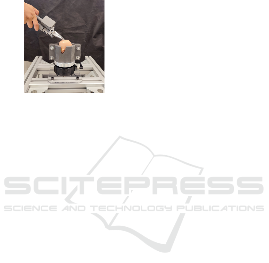
Figure 33: Force testing with the Bota Systems sensor.
erted on the mold during the critical moments of de-
moulding.
The comparative analysis showed an average dif-
ference of 3.28% between both measurements. How-
ever, this value must be interpreted in light of the cu-
mulative measurement errors from both the Bota sen-
sor and the tool’s load cells, as well as the error intro-
duced when calculating the net force by projecting it
along the extraction axis using the orientation angles
provided by the IMU.
5 DISCUSSION
A common thread across both case studies is the
use of embedded sensorized tools to capture hu-
man manipulation strategies in tasks involving de-
formable objects. While the knife and the pliers
address different industrial contexts—meat process-
ing and doll manufacturing, respectively—both tools
were designed to overcome the limitations of external
sensing systems by integrating multimodal perception
directly into ergonomic hand tools. This approach en-
ables the faithful recording of forces, orientations, and
trajectories without interfering with natural operator
behaviour, thereby facilitating knowledge transfer to
collaborative robots.
The quantitative results obtained provide insight
into the practical suitability of these tools for Learn-
ing from Demonstration (LfD). In the knife case, the
observed root mean square error (RMSE) of 2.88 N
between the integrated sensor and the reference sys-
tem indicates a high level of fidelity in force estima-
tion. Considering that typical cutting forces often ex-
ceed 100 N, this error margin is relatively small, sug-
gesting that the captured data are sufficiently accu-
rate for training robotic systems to reproduce cutting
strategies.
For the pliers, the average difference of 3.28%
compared to the Bota Systems force–torque sensor
confirms the ability of the embedded load cells to re-
flect real extraction forces during demoulding. Al-
though this discrepancy arises in part from accumu-
lated measurement uncertainties and the projection
of forces along the extraction axis, the error remains
within an acceptable range. Importantly, LfD frame-
works do not require exact replication of absolute
force values; instead, they benefit from consistent and
accurate capture of relative patterns of pulling and
twisting that characterize the human strategy.
A potential concern when integrating multiple
sensors into a single tool is the possibility of mu-
tual interference, particularly when forces are ap-
plied simultaneously during manipulation. In the case
of the pliers, the two inline load cells are mechani-
cally isolated within the handles and electrically com-
bined into a full Wheatstone bridge, which provides
a net force measurement while inherently canceling
crosstalk. Experimental calibration against a refer-
ence force–torque sensor confirmed linearity and neg-
ligible interference between the two sensors. For
knife prototypes, multiple force-torque sensors were
used in parallel, but each was rigidly mounted in a
mechanically decoupled configuration to separately
capture the operator-applied and task-induced forces.
Although some redundancy exists by design, mechan-
ical adapters and careful alignment minimized the risk
of cross-influence.
Taken together, these results highlight the practi-
cal implications of sensorized tools for skill transfer.
The measured errors both in absolute force (knife)
and in relative accuracy (pliers) are sufficiently low to
enable successful robotic imitation of complex man-
ual tasks. More critically, they demonstrate that task-
specific tool design can balance ergonomic usability
with high-quality data acquisition, which is essential
for bridging the gap between human expertise and
robotic execution.
Nevertheless, certain limitations must be ac-
knowledged. Both case studies were conducted in
controlled scenarios and further testing is necessary
in industrial environments to assess robustness under
variability in materials, operator behavior, and long-
term use. Future work should also explore the extent
to which sensing inaccuracies affect actual task suc-
cess when demonstrations are transferred to robots. In
addition, extending the toolset with complementary
sensing modalities like tactile arrays for the pliers or
additional multi-axis force sensing for the knife may
further improve robustness and generalization across
tasks.
COBOTA 2025 - Special Session on Bridging the Gap in COllaborative roBOtics: from Theory to real Applications
564

6 CONCLUSIONS
This work contributes to the automation of de-
formable object manipulation by introducing sen-
sorized handheld tools designed to capture human
strategies during soft object handling. Focusing on
two representative tasks, such as demoulding of vinyl
parts in toy manufacturing and meat cutting in food
processing, the study presents the design and vali-
dation of custom end-effectors equipped with multi-
modal sensing capabilities. The plier tool integrates
inline load cells and an inertial measurement unit
(IMU) to record force and orientation data under real-
istic working conditions using a simulated mold. The
knife tool setup includes multiple force/torque sen-
sors and a sensorized handle, tested in a Freedrive
mode against a static fixture. All components were
synchronized via ROS, enabling consistent data ac-
quisition for future Learning from Demonstration
(LfD) applications. While full cobotic manipulation
and LfD reproduction are beyond the scope of this
study, the experimental results confirm the tools’ abil-
ity to capture nuanced manipulation strategies with-
out interfering with natural operator behavior. These
findings validate the feasibility of embedding multi-
modal sensing into handheld and robotic tools, lay-
ing the groundwork for future integration into collab-
orative robotic workflows. Future work will focus on
closing the LfD loop by transferring captured demon-
strations to robotic platforms and evaluating perfor-
mance in real collaborative tasks. Additionally, the
sensorized knife will be embedded into a multimodal
feedback system to support real-time trajectory adap-
tation within robot control loops.
ACKNOWLEDGEMENTS
This work was funded by the Spanish Ministry of
Science, Innovation and Universities (Ref. MI-
CIU/AEI/10.13039/501100011033) through the re-
search project FedeMINDex (Ref. CNS2024-
154907), by the Interreg VI-B SUDOE Programme
through the research project ROBOTA-SUDOE (Ref.
S1/1.1/P0125), and by the European Union (European
Regional Development Fund - ERDF). The authors
would also like to thank Titouan Brianc¸on and Mat-
teo Proverbio for their valuable assistance during the
experimental phase of this research.
REFERENCES
Aly, B. A., Low, T., Long, D., Baillie, C., and Brett, P.
(2023). Robotics and sensing technologies in red meat
processing: A review. Trends in Food Science & Tech-
nology, 137:142–155.
Choi, S., Zhang, G., Fuhlbrigge, T., Watson, T., and Tallian,
R. (2013). Applications and requirements of indus-
trial robots in meat processing. In IEEE International
Conference on Automation Science and Engineering
(CASE).
de Medeiros Esper, I., From, P. J., and Mason, A.
(2021). Robotisation and intelligent systems in abat-
toirs. Trends in Food Science & Technology, 108:214–
222.
Heeb, B. (2008). A general calibration algorithm for 3-axis
compass/clinometer devices. CREG Journal, pages
12–18.
Li, Q. and Griffiths, J. G. (2004). Least squares ellipsoid
specific fitting. In Proceedings of the Geometric Mod-
eling and Processing Conference (GMP), pages 335–
340. IEEE Computer Society.
Long, D., Khalil, W., and Martinet, P. (2014a). Force/vision
control for robotic cutting of soft materials. In
IEEE/RSJ International Conference on Intelligent
Robots and Systems (IROS).
Long, D., Khalil, W., and Martinet, P. (2014b). Robotic
deformable object cutting: From simulation to exper-
imental validation. In European Workshop on De-
formable Object Manipulation.
Maithani, H., Ramon, C., Alexandre, J., Lequievre, L.,
Mezouar, Y., and Alric, M. (2021). Exoscarne: As-
sistive strategies for an industrial meat cutting system
based on physical human–robot interaction. Applied
Sciences, 11(9):3907.
Mason, A., Romanov, D., Cordova-Lopez, L. E., and Ko-
rostynska, O. (2022). Smart knife: Integrated intelli-
gence for robotic meat cutting. IEEE Sensors Journal,
22(21):20475–20483.
Nabil, E., Belhassen-Chedli, and Grigore, G. (2015). Soft
material modeling for robotic task formulation and
control in the muscle separation process. Robotics and
Computer-Integrated Manufacturing, 32:37–53.
S
´
anchez-Mart
´
ınez, D., Jara, C. A., and Gomez-Donoso, F.
(2023). A new automatic method for demoulding plas-
tic parts using an intelligent robotic system. The In-
ternational Journal of Advanced Manufacturing Tech-
nology, 129:3109–3121.
Song, P., Corrales Ram
´
on, J. A., and Mezouar, Y. (2022).
Dynamic evaluation of deformable object grasping.
IEEE Robotics and Automation Letters, 7(2):4392–
4399.
Zakaria, M. H. D., Aranda, M., Lequi
`
evre, L., Lengagne,
S., Corrales Ram
´
on, J. A., and Mezouar, Y. (2022).
Robotic control of the deformation of soft linear ob-
jects using deep reinforcement learning. In 2022 IEEE
18th International Conference on Automation Science
and Engineering (CASE), pages 1516–1522. IEEE.
Design and Validation of Sensorized Tools for Deformable Object Manipulation in Meat Cutting and Doll Demoulding
565
