
Design and Field Evaluation of a Robotic Cotton Harvester with
Improved Structural Balance and Suction Mechanism
Van Patiluna
1
, Joe Mari Maja
1
, Aashish Karki
2
and Edward Barnes
3
1
Center of Applied Artificial Intelligence for Sustainable Agriculture, South Carolina State University,
300 College St, Orangeburg, SC, U.S.A.
2
Department of Plant and Environmental Sciences, 171 Poole Agricultural Center, Clemson, SC, U.S.A.
3
Cotton Incorporated, 6399 Weston Parkway, Cary, NC 27513, U.S.A.
Keywords: Cotton Harvester, Robotics, Simulation.
Abstract: Mechanization in the cotton industry increased efficiency and productivity by reducing reliance on manual
labor and improving overall output. Automation and robotics have been increasingly integrated into cotton
production in the United States to address various challenges and enhance agricultural efficiency. Using
robotics and automation in agriculture is a widespread idea whose technical feasibility has already been
proven in several studies. The objective of this study is to design and implement a new robotic cotton harvester
addressing the problems encountered with the previous design. It featured a redesigned finger roller and an
optimized chassis to improve balance and structural integrity. The new design utilizes the same Amiga robotic
platform that is capable of heavy loads such as the header assembly and power generators. A field experiment
assessed harvesting efficiency under three different duty cycles corresponding to the speed of front finger
rollers. During the experiment, the new design experienced clogging of the eductor inlet hindering the
movement of cotton bolls to the collecting bin, which reduced harvesting efficiency. Although the harvesting
efficiency was lower than ideal, it was still slightly better than the previous design. Adjusting the speed of the
front finger rollers has no significant effect on the boll and trash collected, suggesting that lower speeds are
ideal. The static stress simulation of the chassis revealed a better balance and structural integrity than the
previous design. Overall, the new design of the cotton harvesting robot had better structural integrity, however,
it requires further improvements to address clogging of the eductor inlet to move the fibers from the header
assembly to the collecting bin, minimize the trash content and improve harvesting efficiency.
1 INTRODUCTION
Mechanization in the cotton industry has brought both
significant benefits and challenges by increasing
productivity by reducing reliance on manual labor but
also raised concerns about labor displacement and the
impact on traditional harvesting practices (Peterson &
Kislev, 1986). The adoption of machine harvesting
was driven largely by increased nonfarm wages and
the declining cost of mechanized harvesting,
reflecting the interplay between economic incentives
and technological advancements (Peterson & Kislev,
1986). This transition reshaped labor markets in
cotton-producing regions, with many traditional
cotton pickers shifting to other sectors such as
manufacturing (Jung, 2018).
Despite these economic gains, mechanization has
also raised environmental and sustainability
concerns. Cotton cultivation places considerable
pressure on natural resources such as land and water,
contributing to issues like soil degradation and the
overuse of pesticides (Natálio & Maria, 2018).
In response to these challenges, automation and
robotics have been increasingly integrated into U.S.
cotton production to enhance efficiency and
sustainability (Barnes et al., 2021). Recent
advancements in precision agriculture, improved
irrigation systems, and novel cotton varieties have
enabled the development of autonomous multi-
purpose robotic platforms (Maja et al., 2021). These
platforms streamline operations, optimize resource
use, and reduce the need for chemical inputs.
Currently, most cotton in the U.S. is harvested
using large, heavy mechanical pickers (EPA, 2025).
The weight of these machines causes soil compaction,
which reduces long-term soil productivity (Al-Shatib
Patiluna, V., Maja, J. M., Karki, A. and Barnes, E.
Design and Field Evaluation of a Robotic Cotton Harvester with Improved Structural Balance and Suction Mechanism.
DOI: 10.5220/0013945700003982
Paper published under CC license (CC BY-NC-ND 4.0)
In Proceedings of the 22nd International Conference on Informatics in Control, Automation and Robotics (ICINCO 2025) - Volume 2, pages 647-654
ISBN: 978-989-758-770-2; ISSN: 2184-2809
Proceedings Copyright © 2025 by SCITEPRESS – Science and Technology Publications, Lda.
647
et al., 2021; Lagnelov et al., 2023; Antille et al.,
2016). Furthermore, the high cost of such equipment
requires large-scale operations of 600 to 800 hectares
to justify a single machine (Barnes et al., 2021).
Several robotic cotton harvesting systems have
been proposed to address these limitations. Examples
include a wet/dry vacuum cleaner-based harvester
(Fue et al., 2021), a Cartesian manipulator with a
suction-based end-effector (Maja et al., 2021), and a
three-fingered robotic end-effector using a pin tape
mechanism (Gharakhani et al., 2022). A notable
recent approach involves finger roller-based pickers,
which collect bolls in bulk rather than individually, as
demonstrated by Mail et al. (2023) at Clemson
University. This method forms the foundation for the
improved robotic harvester developed in this study.
The objective of this study is to design, build, and
evaluate an improved robotic cotton harvester that
addresses the mechanical limitations and
performance issues identified in the previous
prototype. A new prototype was developed,
incorporating a redesigned finger roller and an
optimized chassis, and was evaluated through static
stress simulations and field experiments.
2 MATERIALS AND METHODS
2.1 Harvester Design
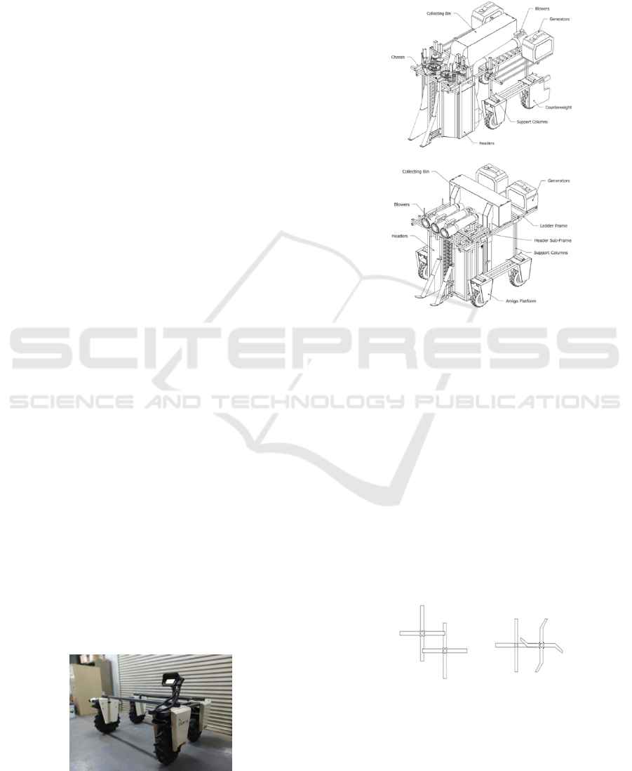
A new cotton harvester prototype was designed based
on the findings from the previous prototype built. It
maintained the same mechanism for collecting the
cotton bolls that is using finger rollers to pluck the
cotton bolls and an eductor system to move the bolls
to the collecting bin. It also used the same robotic
platform Amiga developed by Farm-NG
(Watsonville, CA, USA) as shown in Figure 1.
Instead of using belts and pulleys to drive the
finger rollers, an angled gearbox was used with 1:1
gear ratio used for the front rollers and 1:2 for the rear
rollers. To produce the vacuum at the eductor, an 800
CFM leaf blower was utilized. A third blower was
added to create to positive air pressure to blow the
cotton bolls accumulating in the eductor inlet.
Figure 1: Amiga robotic platform with bare chassis.
Two 2200-Watt generators were used to power the
blowers, motors and electronics system of the
harvester. The Amiga platform was powered by its
own battery pack. Figure 2 shows the sketch of the
previous design (a) and new design (b).
(a)
(b)
Figure 2: Sketches of the previous design (a) and the new
design (b).
The rollers were driven by a 100 rpm and 320 rpm
planetary gear motors for the front and rear rollers
respectively. The speed of the front rollers can be
adjusted to three duty cycles: 25%, 50% and 100%.
The shaft speed of the rear rollers was fixed at 320
rpm enough to pluck the cotton bolls from the fruiting
branch. Powering the motors were 2x15A and 2x30A
RoboClaw (BasicMicro, Temecula, CA, USA) motor
controllers. The configuration of the front finger
roller was modified as shown in Figure 3. In the
previous design, the front and rear rollers were offset
at an angle of about 54 degrees (Figure 3a). In the
revised design, the rollers are aligned side-by-side
(Figure 3b).
(a) (b)
Figure 3: Finger roller orientation of the previous design (a)
and new design (b).
The offset in the original design aimed to narrow the
header but reduced the rear roller's effectiveness,
TISAS 2025 - Special Session on Trustworthy and Intelligent Smart Agriculture Systems: AI, Blockchain, and IoT Convergence
648
since it only hit cotton bolls pulled deep enough by
the front roller. By aligning the rollers side-by-side,
cotton bolls do not have to be pulled deep enough to
be reached by the rear finger rollers (Maja et. al.,
2024). The fingers were made of aluminum, laser cut
to have 15-degree bend (Figure 3b).
The new design also focused on improving the
structural integrity of the robot chassis, addressing the
observed stresses and displacements from the field
trials of the previous design. Structural improvements
were introduced. First, ground clearance could be
adjusted through a separate sub-frame (Figure 2b). It
can be raised to adjust the ground clearance up to a
maximum travel of 100 mm. Secondly, the balance of
the entire robot can be adjusted by sliding the ladder
frame front or back. All the robots’ components
including the headers, ducts, collecting bin, blowers,
electronics and generators were mounted on the
ladder frame. This free movement of the ladder frame
allows the load to be moved along the support
columns to adjust the balance and weight distribution
as needed. A third blower was added to produce
positive air pressure to clear out stuck cotton bolls and
trash on the eductor inlet. The new design widened
the chassis by 4.3% to 1.62 m, while maintaining a
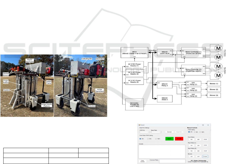
wheelbase of 0.96 m. Figure 4 shows the completed
robot.
(a) (b)
Figure 4: Front (a) and rear (b) views of the completed
assembly of the robotic cotton harvester.
Table 1: Weights of the load components.
Componen
t
Previous New
Header gross weigh
t
75.47 kg 85.79 kg
Generator dry weight 24.99 kg (245.06 N)
Static-stress simulation of the chassis of the
previous and new design was conducted to evaluate
the structural integrity of the chassis using Autodesk
Fusion (Autodesk, San Francisco, CA, USA).
Simulated loads of the heavy components such as the
header assembly and power generators were applied
to the chassis (see Table 1). Mechanical properties of
the materials used of the construction of the chassis
such as AISI 1018 and Aluminum 6061 (header
assembly) and 5052 H32 (chassis) were used applied
in the materials properties for simulation. Load was
also applied to the header assembly equivalent to the
bending force of a cotton stalk, about 63.64 N
(Khudayarov et. al., 2022; Zao et. al., 2022).
The load setup will provide the ultimate loads test
for the chassis. Once simulations were completed,
key parameters such as von Mises stress,
displacement, strain and safety factors were analyzed
using visualization tools and quantitative metrics
provided by the simulation software (Jahanbakhshi
et.al., 2019).
2.2 Control System
A MikroE Clicker 4 for STM32F (Belgrade, Serbia)
microcontroller board was used to control the motors,
blowers and handles wireless communication with
the base computer. Attached to the Clicker 4 board
were UART MUX 4 Click (to handle serial
communication with the motor controllers), Relay 5
Click (to control the AC power to the blowers) and
XBee 3 Click (for wireless communication). Figure 5
shows the block diagram of the control system.
Figure 5: Control system block diagram.
Figure 6: Dashboard and control software.
Three 24V DC power supply powered the
microcontroller and motor controllers. These power
supplies were also powered by a 120V AC coming
from the combined output the two generators through
a parallel kit. A dashboard software was developed to
Design and Field Evaluation of a Robotic Cotton Harvester with Improved Structural Balance and Suction Mechanism
649
control the system remotely (Figure 6). It featured an
automatic startup sequence (start button) and system-
wide shut down (stop button).
An automatic startup sequence was implemented
to manage the proper activation order of the motors
and blowers, thereby preventing power surges caused
by simultaneous current draw. The startup
configuration also enables pre-selection of the front
roller speed, which can be set to 25%, 50%, or 100%
duty cycle—corresponding to approximate shaft
speeds of 25 rpm, 50 rpm, and 100 rpm, respectively.
In addition to the automated sequence, the dashboard
software provides manual control options. An XBee
transceiver connected to the base computer facilitates
wireless communication with the controller module.
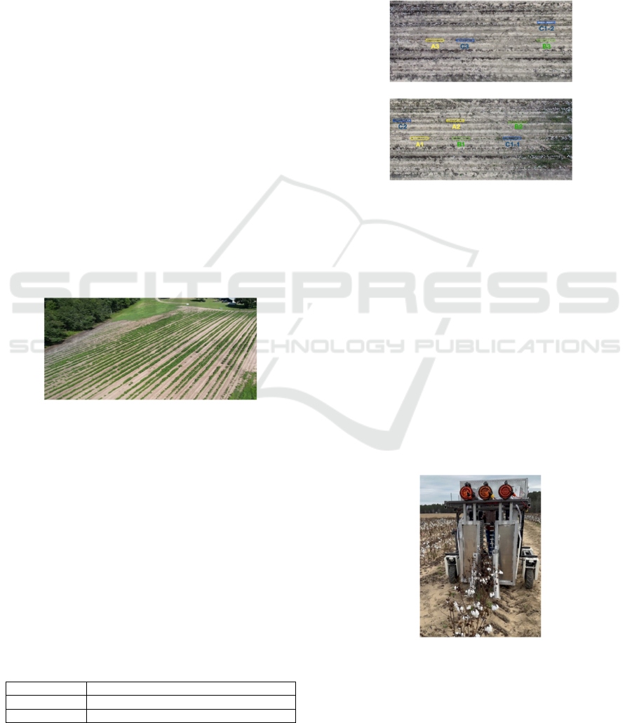
2.3 Study Site
The experiment and data collection were conducted
at the South Carolina State University Research and
Demonstration Farm in Olar, SC, USA (33.162161, -
81.136361). The cotton variety used was Deltapine
DP 2127 B3XF. The field was planted in a 1:1 skip-
row configuration to accommodate the robotic
harvester and to provide maneuvering space for the
research crew. Figure 7 shows an aerial view of the
cotton field used for the experiment.
Figure 7: Aerial shot of the cotton farm at SC State
Research and Demonstration farm.
Due to planting delays, cotton was sown on June 14,
2024. Chemical defoliants were applied on November
27, 2024, and the harvesting experiments were
conducted approximately one month later, on
December 23, 2024.
The experimental design followed a completely
randomized design (CRD) with three (3) treatments
and three (3) replications per treatment. The objective
was to evaluate the effect of front finger roller speed
on the number of cotton bolls and the amount of trash
collected during harvesting. Details of each treatment
are provided in Table 2.
Table 2: Experiment Treatment Details.
Treatment A Front finger rollers at 50% duty cycle.
Treatment B Front finger rollers at 25% duty cycle.
Treatment C Front finger rollers at 100% duty cycle.
A total of nine rows were selected and prepared
for the study. Each row measured 3 meters in length,
with a minimum buffer zone of 1.5 meters between
rows to prevent cross-contamination and allow robot
maneuverability. The layout and locations of the
treatment rows are shown in Figure 8. To minimize
the time and effort required to reposition the robot
between rows, an optimized experimental sequence
was developed.
(a)
(b)
Figure 8: Selected treatment rows with buffer zones: (a)
Treatments A3, C3, B3 and C1; (b) Treatments A1, A2, B1,
B2 and C2. C1-1 was replaced by C1-2 as treatment C1.
Instead of running treatments in a strict numerical
order, the robot followed a path that allowed for the
most efficient traversal across the field. The sequence
was as follows: A1-B1-C1-B2-A2-C2-B3-C3-A3.
The robot was configured with the appropriate
duty cycle setting for the front finger rollers, based on
the treatment assignment. The startup sequence was
executed using the developed dashboard software to
ensure that the motors for both the front and rear
rollers started in the correct order. The robot was
positioned at the center of the selected row (Figure 9)
and driven forward at a constant speed of
approximately 0.2 m/s.
Figure 9: Harvester robot positioned to harvest cotton bolls
from the treatment row.
Cotton bolls were collected from four distinct
locations: (1) inside the collecting bin, (2) within the
TISAS 2025 - Special Session on Trustworthy and Intelligent Smart Agriculture Systems: AI, Blockchain, and IoT Convergence
650
eductor duct, (3) on the ground, and (4) remaining
unharvested on the plant. The collected bolls were
placed into separate, labeled paper bags for each
treatment. After the experiment, cotton fibers were
separated from foreign materials such as leaves and
stalk fragments that were inadvertently collected
during harvesting. The cleaned cotton fiber and
associated trash were then weighed separately.
Due to the mechanical damage inflicted by the
harvesting process, most bolls were too mangled to be
counted individually. To estimate the number of
cotton bolls collected from each source (bin, header,
ground, and plant), the total fiber weight was divided
by 5.3 grams—the average weight of a single
Deltapine DP 2127 B3XF cotton boll. The average
boll weight was determined by sampling and
weighing intact bolls from the same experimental
field. After the number of cotton bolls were
determined, the harvesting efficiency of the robotic
cotton harvester was calculated using Equation (1).
𝑒𝑓𝑓𝑖𝑐𝑖𝑒𝑛𝑐𝑦
𝑜𝑢𝑡𝑝𝑢𝑡
𝑖𝑛𝑝𝑢𝑡
𝑥100%
(1)
where:
output – number bolls collected in the bin
input – total number of cotton bolls collected
The input data included the estimated number of
cotton bolls collected from four locations: the
collecting bin, header assembly, ground, and
remaining on the plant. Trash content, consisting
primarily of leaves, stems, and other debris, were
quantified by its weight relative to the total harvested
material.
To calculate the percentage of trash collected in the
bin and header assemblies, Equation (2) below was
used.
% 𝑡𝑟𝑎𝑠ℎ
𝑡𝑟𝑎𝑠ℎ 𝑤𝑒𝑖𝑔ℎ𝑡
𝑡𝑟𝑎𝑠ℎ
𝑓
𝑖𝑏𝑒𝑟 𝑤𝑒𝑖𝑔ℎ𝑡
𝑥100%
(2)
Trash found on the ground and on the plant were
excluded from analysis, as it was not mechanically
collected during the experiment and therefore not
attributable to the harvester's performance.
3 RESULTS
3.1 Static Stress Analysis of the Chassis
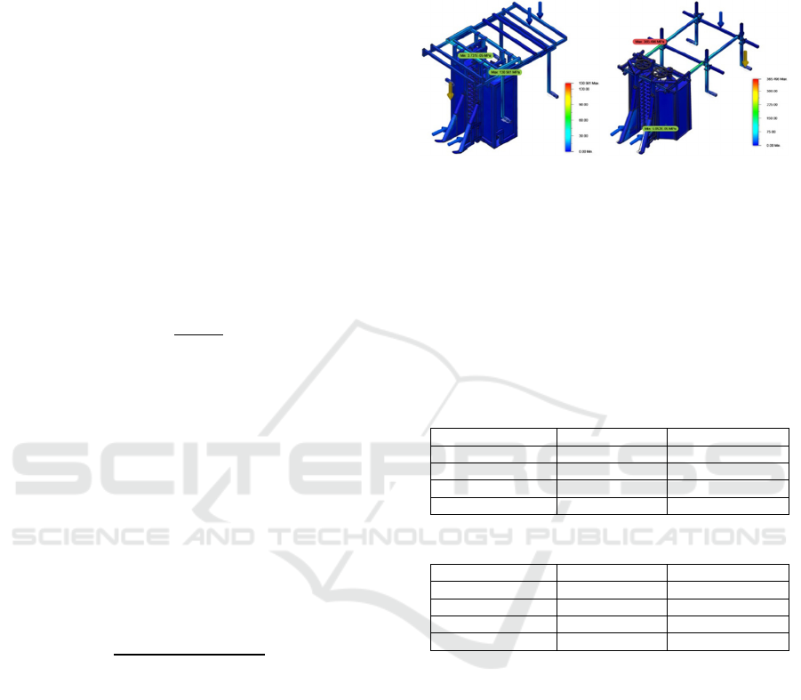
After the simulation, the results revealed a
concentration of stress in the cantilever structure of
the previous design (Figure 10b). In contrast, the new
design exhibited moderate stress localized on one of
the crossbars of the header sub-frame (Figure 10a).
The elevated stress observed in the previous
design was attributed to the header assembly being
supported solely by the front columns of the chassis,
creating a cantilevered overhang effect.
(a) (b)
Figure 10: Stress visualization of the integrated stress
analysis for the (a) previous design and (b) new design
showing von Mises stress.
In the redesigned system, the headers were supported
on all four sides, allowing the load to be distributed
more evenly across the sub-frame. Quantitative
simulation data comparing the two designs is
summarized in Table 3.
Table 3a: Static stress simulation data for the previous
design.
Data Min Max
Stress (von Mises) 5.025E-05 MPa 365.496 MPa
Displacement 0.00 mm 49.383 mm
Strain 4.240E-10 0.003
Safety Facto
r
0.566 15.00
Table 3b: Static stress simulation data for the new design.
Data Min Max
Stress (von Mises) 3.731E-05 MPa 130.981 MPa
Displacement 0.00 mm 3.223 mm
Strain 1.938E-10 0.001
Safety Facto
r
1.58 15.00
The previous design exhibited a significantly
higher von Mises stress of 365.496 MPa, compared to
130.981 MPa observed in the new design. In the
previous design, stress was primarily concentrated at
the frame joints between the cantilever and the
support columns. Both designs experienced strain in
the same high-stress regions, with the previous design
showing a peak strain of 0.003, while the new design
showed a lower value of 0.001. As expected, the
maximum displacement was also greater in the
previous design, measured at 49.38 mm at the stalk
lifter. The simulation did not fully account for
dynamic displacement in the cantilever structure, but
further inspection of the integrated model revealed a
pronounced increase in displacement at the cantilever
section, as illustrated in Figure 11.
Design and Field Evaluation of a Robotic Cotton Harvester with Improved Structural Balance and Suction Mechanism
651
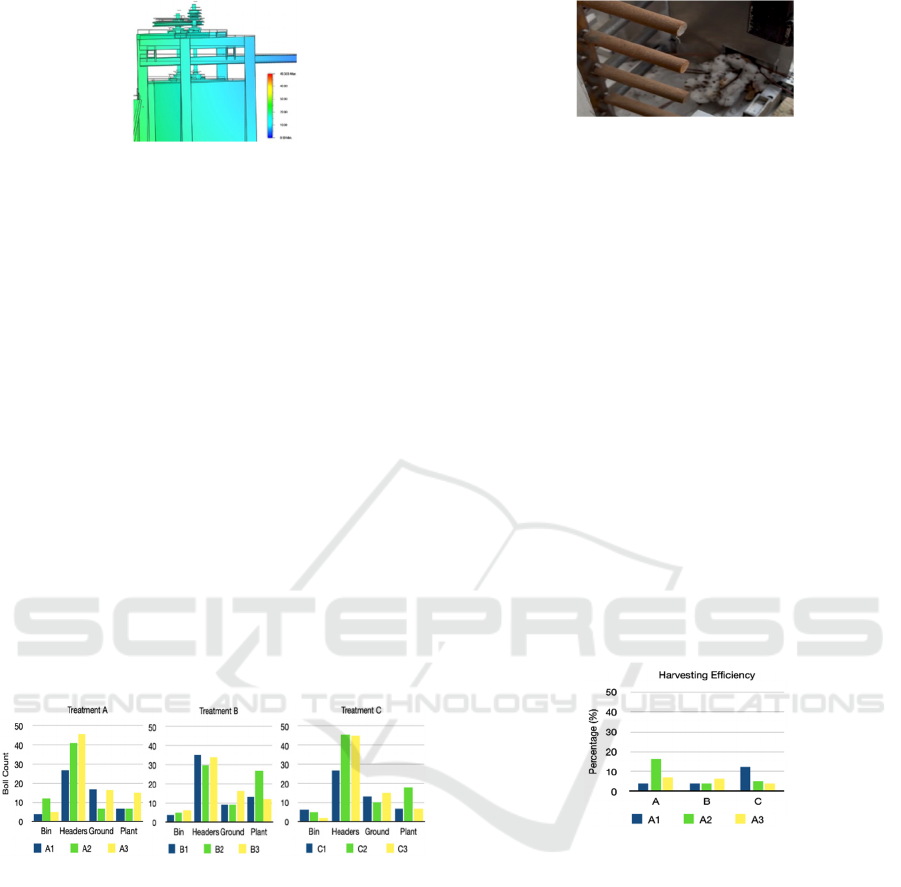
Figure 11: Displacement of the chassis of the previous
design.
The high stress concentration observed in the
previous design resulted in a safety factor of only
0.57, indicating a high risk of permanent deformation
or even material failure under operational loads. This
value fell below both the yield and ultimate tensile
strengths of the material, suggesting structural
inadequacy. In contrast, the new design achieved a
64.18% reduction in von Mises stress compared to the
previous version and exhibited substantially lower
displacement with no bending or deformation.
3.2 Cotton Boll Harvesting
After weighing the collected cotton fibers, the
approximate number of cotton bolls from each
collection point—the collecting bin, inside the
headers, on the ground, and remaining on the plant—
was estimated by dividing the fiber weight by the
average weight of a single boll (5.3 grams).The
estimated distribution of cotton bolls across these
collection points is illustrated in Figure 12.
(a) (b) (c)
Figure 12: Cotton boll count collected from the bin,
headers, ground and plant from (a) Treatment A, (b)
Treatment B, and (c) Treatment C.
The data revealed that most cotton bolls were
collected from within the header assembly (near the
eductor inlet), while the smallest quantity was
recovered from the collecting bin. This indicated that
many bolls were unable to move from the header to
the bin, suggesting a failure in the boll transfer
process. Upon inspection, it was confirmed that
cotton bolls and plant debris had clogged the eductor
inlet (Figure 13), thereby restricting the vacuum
airflow needed to move the material.
Figure 13: Cotton bolls and trash accumulating on the
eductor inlet.
This blockage was likely exacerbated by the long
delay between defoliation and harvesting, during
which colder temperatures caused the plants to
become brittle. Consequently, broken branches and
stalk fragments accumulated at the inlet, further
impeding airflow. The positive air pressure generated
by the third blower, approximately 20 psi, was
insufficient to effectively clear the obstruction.
According to the spindle-type harvester in-season
procedures (Cotton Inc.), it would take around 125 psi
to effectively remove lint build up (cotton fiber) and
trash. Among the treatments, Treatment A yielded the
highest number of cotton bolls transferred to the
collecting bin, while Treatment C had the highest
accumulation within the header.
Due to the blocked/clogged eductor inlet, it was
expected that the harvesting efficiency would be
lower. Although some treatments like A2 and C1
have more than 10% harvesting efficiency, it was
much lower than the ideal of 100%, as shown in
Figure 14.
Figure 14: Harvesting efficiency for the 3 treatment rows.
The average for treatments A, B and C was 9.25%,
4.95% and 7.02% respectively. Treatment B had the
lowest harvesting efficiency while treatment A had
the highest. The previous design has an average
harvesting efficiency of 5.77%, 5.72% and 8.1% for
treatments A, B and C respectively. The new design
has the highest efficiency at 9.25% for treatment A
(50% duty cycle) while the previous has the highest
efficiency at 8.1% for treatment C (100% duty cycle).
The results revealed that the new design has the
highest efficiency when the front finger roller is
rotating at 50 rpm while the previous design achieved
the highest efficiency at full speed of 100 rpm.
Overall, the new design has slightly better results at
50% and 100% duty cycles compared to the previous.
The percentage of trash collected from the
collecting bin, headers, ground and plants are shown
TISAS 2025 - Special Session on Trustworthy and Intelligent Smart Agriculture Systems: AI, Blockchain, and IoT Convergence
652
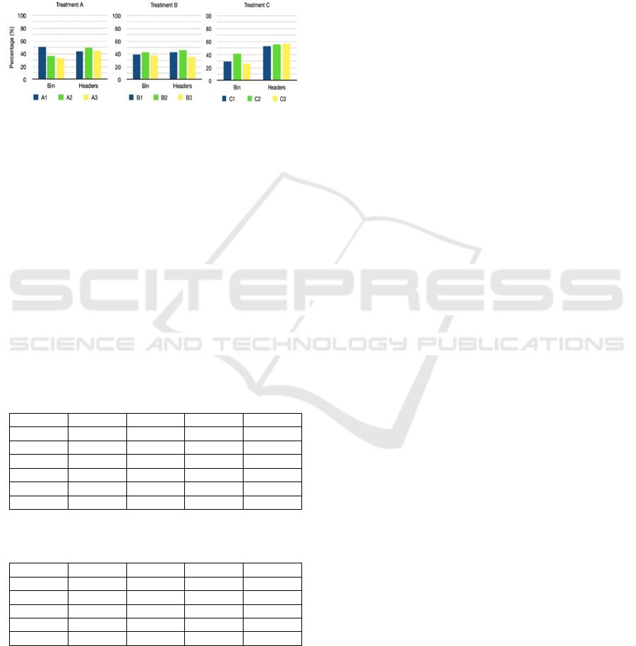
in Figure 15. Treatment C has the least amount of
trash at the collecting bin. It also has the most trash
collected at the headers. Treatments A and B have
below 50% trash in either collecting bin and headers.
The data also shows that almost half of the weight
collected in the collecting bin and headers were trash.
The average trash percentage at the bin were 39.96%,
39.6% and 32.58% for treatments A, B and C
respectively.
(a) (b) (c)
Figure 15: Percentage of trash collected from the collecting
bin and headers among cotton fibers for Treatments A (a),
B (b) and C (c).
Meanwhile, the average trash percentage from the
headers were 46.28%, 41.35% and 55.08% for
treatments A, B and C respectively. Unfortunately,
the data from the previous design only weighed the
branches wrapped around the finger rollers which
excluded the twigs and leaves, therefore comparison
to the current data could not be made.
The effect of the duty cycle applied to the motors
of the front finger roller to the cotton bolls and trash
collected was analyzed using one-way ANOVA.
Table 4 shows the result of the analysis.
Table 4a: Effect of PWM applied to front finger rollers on
number of bolls collected.
Treat B_Bin B_Head B_Gnd B_Plnt
A 5.23 32.50 9.95 15.11
B 3.31 27.19 9.33 15.59
C 3.13 0.19 10.82 6.74
F
0.7057342 0.6981467 0.1536920 0.6351503
p
-value
0.5305679 0.5338403 0.8608073 0.5620781
F
-Cri
t
5.1432529 5.1432529 5.1432529 5.1432529
Table 4b: Effect of PWM applied to front finger rollers on
amount of trash collected.
Treat T_Bin T_Head T_Gnd T_Plnt
A
16.78 156.00 27.25 15.08
B
8.61 101.25 19.19 28.16
C
7.97 185.18 29.27 16.55
F
1.98574193
2.3709049
8.35233882
3.64021987
p
-value
0.21785843
0.1742695
0.00757796
0.06389921
The results revealed no significant differences
between different PWM duty cycles on the number of
bolls collected in the bin (p=0.5305), headers
(p=0.5338), ground (p=0.8608) and plant (p=0.5620)
(Table 3a). This suggests that varying the shaft speed
of the front finger rollers had minimal influence on
the efficiency of harvesting. The amount of trash
collected along with the cotton fibers in the collecting
bin (p=0.2178) and headers (p=0.1742) were also
non-significant (Table 3b), suggesting that the speed
of front finger rollers did not change the trash amount.
Thus, in this scenario, it would be ideal to operate at
lower speeds to reduce energy use and lessen the wear
and tear of the motors.
4 CONCLUSIONS
The new robotic cotton harvester was successfully
designed, constructed, and tested in field conditions.
All core systems functioned as intended, with only
minimal operational issues. However, the field
experiment revealed a critical limitation: a significant
number of cotton bolls failed to reach the collecting
bin due to blockage at the eductor inlet caused by
accumulated trash and fiber. This obstruction reduced
the effectiveness of the vacuum transfer system.
The third blower, intended to generate positive air
pressure to clear the inlet, produced only about 20 psi,
way insufficient to remove blockages during
operation. As a result, most of the harvested bolls
remained within the header, limiting overall
harvesting efficiency. Although the new system
performed slightly better than the previous version at
50% and 100% duty cycles, only a small fraction of
the harvested bolls reached the collecting bin. Trash
content remained high, accounting for at least 50% of
the material collected in both the bin and header
assemblies.
Analysis showed that varying the duty cycle of the
front finger rollers (25%, 50%, 100%) had no
significant effect on the number of cotton bolls
collected or the amount of trash recovered. Therefore,
operating the rollers at the lowest speed (25% duty
cycle or 25 rpm) is recommended, as it reduces power
consumption and mechanical wear without
compromising performance.
The static stress simulation revealed a stark
contrast between the two chassis designs. The
previous version exhibited excessive von Mises stress
at the cantilever structure—6.5 times higher than the
acceptable limit—resulting in a safety factor below 1,
indicating a high risk of permanent deformation or
failure. In contrast, the new design demonstrated
improved stress distribution, minimal displacement,
and enhanced structural integrity under load. The
optimized weight distribution also reduces the load on
the front motors, lowering operating temperatures and
extending motor lifespan.
Design and Field Evaluation of a Robotic Cotton Harvester with Improved Structural Balance and Suction Mechanism
653

While the new robotic harvester marks a
substantial improvement in structural design and
robustness, further enhancements are required to
address boll transfer issues and trash reduction. If
cotton bolls retained in the header were successfully
transferred to the collecting bin, harvesting efficiency
could increase by as much as 60%. Additionally,
implementing strategies to minimize trash intake will
be essential to improve fiber purity and overall
performance.
ACKNOWLEDGEMENTS
The authors gratefully acknowledge Cotton
Incorporated for funding this project under Project
No. 24-061. Special thanks are extended to Ms.
Melissa Mitchell and Dr. Lamin Drammeh of South
Carolina State University 1890 Research & Extension
for their continued support and guidance throughout
the duration of this research.
REFERENCES
Antille, D. L.; Bennett, J. M. L.; Jensen, T. A. (2016) Soil
compaction and controlled traffic considerations in
Australian cotton-farming systems. Crop Pasture Sci.,
67, 1–28. http://dx.doi.org/10.1071/CP15097
Barnes, E.; Morgan, G.; Hake, K.; Devine, J.; Kurtz, R.;
Ibendahl, G.; Holt, G. (2021) Opportunities for Robotic
Systems and Automation in Cotton Production.
Agriengineering, 3, 339–362. https://doi.org/10.3390/
agriengineering3020023
Cotton Inc. (2025, September 11). The Spindle-Type
Cotton Harvester In-Season Procedures https://www.c
ottoninc.com/cotton-production/ag-resources/harvest-
systems/the-spindle-type-cotton-harvester/in-season-
procedures.
EPA, U.S. Environmental Protection Agency. Available
online: https://www3.epa.gov/ttn/chief/ap42/ch09
/final/c9s03-1.pdf (accessed 12 July 2025).
Fue, K.; Porter, W.; Barnes, E.; Li, C. (2020) Rains, G.
Center-articulated hydrostatic cotton harvesting rover
using visual-servoing control and a finite state machine.
Electron, 9, 1–21. https://doi.org/10.3390/electronics
9081226
Fue, K.; Porter, W.; Barnes, E.; Li, C.; Rains, G. (2020)
Evaluation of a Stereo Vision System for Cotton Row
Detection and Boll Location Estimation in Direct
Sunlight. Agronomy, 10, 1137. https://doi.org/10.3390/
agronomy10081137
Gharakhani, H., Thomasson, J.A. Lu, Y. (2022) An end-
effector for robotic cotton harvesting. Smart
Agricultural Technology, Vol. 2. https://doi.org/10.1
016/j.atech.2022.100043
Jahanbakhshi, A.; Heidarbeigi, K. (2019) Simulation and
Mechanical Stress Analysis of the Lower Link Arm of
a Tractor Using Finite Element Method. Journal of
Failure Analysis and Prevention, 19, 1666–1672.
https://doi.org/10.1007/s11668-019-00763-2
Jung, Y. (2018). The legacy of king cotton: agricultural
patterns and the quality of structural change. SocArXiv.
https://doi.org/10.31235/osf.io/trjfz
Khudayarov, B.M; Kuziev, U.T.; Sarimsakov, B.R.;
Khuydaykulov, R.F. (2022) Dependence of the bending
force on the morphology of cotton stems and on the
parameters of the stalk bender. IOP Conf. Ser.: Earth
Environ. Sci., 1076 012045. https://doi.org/10.10
88/1755-1315/1076/1/012045
Lagnelöv, O.; Larsson, G.; Larsolle, A.; Hansson, P. (2023)
Impact of lowered vehicle weight of electric
autonomous tractors in a systems perspective. Smart
Agricultural Technology, 4, 100156. https://doi.org/1
0.1016/j.atech.2022.100156
Mail, M.F., Maja, J.M., Marshall, M., Patiluna, V., Cutulle,
M., Miller, G., Bridges, W., Barnes, E. (2024)
Development of New Cotton Harvesting Robot. In
2024 Beltwide Cotton Conference, Fort Worth, TX,
USA, 3-5 January 2024, pp. 649-657.
Maja, J.M., Mail, M.F., Patiluna, V., Miller, G., Cutulle,
Marshall, M., Barnes, E. (2024) A new mobile robot
harvesting prototype for cotton production. In AgEng
2024 Conference, Athens, Greece, 1-4 July 2024, pp.
328-336.
Maja, J.; Polak, M.; Burce, M.; Barnes, E. (2021) CHAP:
Cotton-Harvesting Autonomous Platform.
Agriengineering, 3, 199–217. https://doi.org/10.3390/a
griengineering3020013
Natálio, F. and Maria, R. (2018). Structural evolution of
gossypium hirsutum fibers grown under greenhouse
and hydroponic conditions. Fibers, 6(1), 11.
https://doi.org/10.3390/fib6010011
Peterson, Willis & Kislev, Yoav. (1986). The Cotton
Harvester in Retrospect: Labor Displacement or
Replacement? The Journal of Economic History, 46(1),
199-216.
Zhao, W.; Xie, J.; Wang, Z.; Gao, Q.; Chen, M. (2022)
Investigation of mechanical properties of cotton stalk
based on multi-component analyses. Int. Agrophys., 36,
257-267. https://doi.org/10.31545/intagr/152488
TISAS 2025 - Special Session on Trustworthy and Intelligent Smart Agriculture Systems: AI, Blockchain, and IoT Convergence
654
