
Automated Computational Workflow for the Parametric Design and
Optimization of a 3D-Printed Fin Ray Effect Soft Robotic Finger
Rodrigo Antunes
1,2 a
, Luan Lang
1b
, Martim Lima de Aguiar
1,2 c
, Nuno José Matos Pereira
1,2 d
,
Thiago Assis Dutra
1,2 e
, Yebo Lu
3f
and Pedro Dinis Gaspar
1,2 g
1
C-MAST, Centre for Mechanical and Aerospace Science and Technologies,
University of Beira Interior, Calçada Fonte do Lameiro 6, 6200-358, Covilhã, Portugal
2
Department of Electromechanical Engineering, University of Beira Interior,
Calçada Fonte do Lameiro 6, 6200-358, Covilhã, Portugal
3
College of Mechanical Engineering, Jiaxing University, Jiaxing, Zhejiang province, 314001, China
Keywords: Soft Robotic Finger, Computational Design, Fin Ray Effect, Parametric Optimization,
Finite Element Analysis, Additive Manufacturing, PyAnsys, Soft Grippers.
Abstract: The design of soft grippers is challenged by the complex, non-linear coupling of material properties, geometry,
and control, rendering traditional design methods inefficient. To address this, this paper presents an automated
computational workflow for the parametric design and optimization of a 3D-printed Fin Ray Effect soft
robotic gripper finger. The tool establishes a closed-loop digital thread, connecting a web-based parametric
design interface using FreeCAD to a finite element analysis backend driven by PyAnsys. A parametric study
was conducted, varying the number of internal crossbeams from 1 to 16, to analyse the gripper's performance
using an experimentally validated hyperelastic model for TPU 60A. The results show a trade-off between
contact pressure and pressure distribution, with an optimal configuration of 14-16 crossbeams identified for
applications requiring a gentle grip with low-pressure concentrations. The developed workflow proved to be
an effective method for rapidly iterating through designs and identifying an optimal solution, showcasing the
power of automated simulation in the Design for Additive Manufacturing (DfAM) process.
1 INTRODUCTION
The field of robotics is evolving from a predominant
emphasis on precision through rigidity toward an
increasing integration of adaptability through
compliance. For decades, rigid-linked robots have
been the standard, however, they face considerable
challenges when operating in unstructured, human-
centric environments where safe interaction is
required. Soft robotics presents an alternative, using
materials such as elastomers and gels with moduli of
elasticity, typically ranging from 10
to 10
Pa,
which are comparable to biological tissues (Zhang et
a
https://orcid.org/0009-0002-6599-6905
b
https://orcid.org/0000-0002-2857-3092
c
https://orcid.org/0000-0003-0672-0378
d
https://orcid.org/0000-0001-7177-751X
e
https://orcid.org/0000-0002-3576-5703
f
https://orcid.org/0000-0002-8995-370X
g
https://orcid.org/0000-0003-1691-1709
al., 2020). This material choice gives soft robotic
grippers an inherent compliance (Nonaka et al.,
2023), which enables them to passively adapt to
objects of diverse and irregular shapes, absorb impact
energy and reduce the need for complex control
systems through a concept known as embodied
intelligence (Ponce et al., 2021).
However, the very nature of these materials
creates design challenges (Stella & Hughes, 2023),
unlike in rigid robotics, the behaviour of a soft robot
is governed by a tight, nonlinear coupling of its
material properties, geometric morphology, and
control inputs. This complexity renders traditional,
Antunes, R., Lang, L., Lima de Aguiar, M., Pereira, N. J. M., Assis Dutra, T., Lu, Y. and Gaspar, P. D.
Automated Computational Workflow for the Parametric Design and Optimization of a 3D-Printed Fin Ray Effect Soft Robotic Finger.
DOI: 10.5220/0013944900003982
Paper published under CC license (CC BY-NC-ND 4.0)
In Proceedings of the 22nd International Conference on Informatics in Control, Automation and Robotics (ICINCO 2025) - Volume 2, pages 577-584
ISBN: 978-989-758-770-2; ISSN: 2184-2809
Proceedings Copyright © 2025 by SCITEPRESS – Science and Technology Publications, Lda.
577

intuition-based design methods inefficient and has
created a need for advanced computational tools to
navigate the design space effectively (Xie, Pinskier,
et al., 2024).
To address this challenge, this paper presents an
integrated computational workflow that automates
the design and analysis of Fin Ray Effect (FRE) Soft
Robotic Gripper Fingers (SRGF). The framework
uses a web application to parametrically generate
geometries in FreeCAD, which are then analysed
using a Finite Element Method (FEM) simulation
controlled programmatically via the PyAnsys library.
The utility of this pipeline is demonstrated through a
parametric study investigating the influence of
internal crossbeam density on grasping forces and
contact pressures, thereby contributing a practical
tool for the principled design of high-performance
soft robotic grippers.
2 LITERATURE REVIEW
2.1 Computational Approaches to
Complex Design
Despite these conceptual advantages, the potential of
soft grippers is constrained by the complexity
inherent in their design (Stella & Hughes, 2023).
Addressing these design complexities effectively
requires moving beyond intuition-based approaches
toward computational methods capable of navigating
the high-dimensional and nonlinear design space of
soft robotic grippers (Yi et al., 2025).
To overcome this, the field has increasingly
embraced computational simulation as a tool for
creating principled and optimized designs (Xie,
Pinskier, et al., 2024). This approach formalizes the
creative design process into an optimization task
within a defined parameterized design space (Stella &
Hughes, 2023). Researchers have focused on
parameterizing key design variables, such as the
spatial stiffness distribution for balancing compliance
and force transmission, the geometry of pneumatic
chambers for actuation (Navez et al., 2025), the finger
arrangement and frame design, the selection and
combination of materials to achieve controlled
motion (Jin et al., 2024). The search for optimal
parameters within this complex landscape has led to
the widespread adoption of artificial intelligence
techniques (Xie, Wang, et al., 2024). Methods such as
Genetic Algorithms—which use a fitness function
evaluated via simulation to evolve a population of
designs —and Deep Reinforcement Learning have
become mainstays in the field. A significant
bottleneck, however, is the computational cost of
fitness evaluation, which has been addressed by the
use of Neural Network Surrogates to accelerate the
process (Garcia et al., 2024).
Beyond parameter-based methods, more free-
form approaches like topology optimization have
been used to discover novel structures (Xie, Pinskier,
et al., 2024). Furthermore, a holistic view recognizes
that performance is determined by the synergy
between morphology and control, leading to the goal
of co-design—the simultaneous optimization of the
robot's body and brain (Yi et al., 2025).
2.2 High-Fidelity Simulation with the
Finite Element Method
At the core of any computational design framework
resides the simulation engine, which predicts the
physical behaviour of the gripper. The FEM allows
for modelling hyperelastic body dynamics (Elgström,
2014), it is particularly well-suited for the challenges
of soft robotics, which involve large, nonlinear
material deformations. The process involves the
discretization of the geometry into simpler elements
and nodes, the reformulation of governing equations
into a weak form, and the iterative solution of a large
nonlinear system of equations, often using the
Newton-Raphson method (Megan & Croop, 2014).
Modelling the hyperelastic behavior of
elastomers was achieved using constitutive models
such as the Neo-Hookean, Mooney-Rivlin, Yeoh and
Polynomial models. An important step for simulation
accuracy is the derivation of material coefficients by
fitting these models to experimental test data, as these
parameters are not typically found in datasheets
(ANSYS Inc., 2017).
For gripper design, FEM allows for the simulation
of contact mechanics—a challenging and non-smooth
phenomenon. This includes enforcing non-
penetration constraints, modelling friction, and
analysing the resulting forces and pressure
distributions during a grasp (Dassault Systèmes,
2018). For tasks that demand the highest degree of
physical accuracy and validation, industry-standard
commercial FEM packages like Ansys and ABAQUS
are the preferred choice and are considered the gold
standard for design verification (Han et al., 2020).
The constant tension between simulation fidelity and
computational speed remains a central engineering
dilemma, driving the development of techniques like
Reduced Order Modeling (Guo & Hesthaven, 2018)
and learned surrogate models to manage this trade-off
(Navez et al., 2025).
COBOTA 2025 - Special Session on Bridging the Gap in COllaborative roBOtics: from Theory to real Applications
578

2.3 Integrated and Automated
Workflows
The ultimate objective in computational design is the
creation of fully automated pipelines that can
autonomously discover, optimize, and validate novel
designs. Recent breakthroughs in differentiable
simulation and Quality Diversity (QD) algorithms are
bringing this vision closer to reality (Xie, Wang, et
al., 2024). Differentiable simulation allows for the
use of highly efficient, gradient-based optimization
algorithms (Connolly et al., 2015), while QD
algorithms like MAP-Elites aim to generate a diverse
archive of high-performing solutions rather than a
single optimum (Xie, Pinskier, et al., 2024).
A technological enabler for automation is the
development of Python libraries that provide
programmatic access to powerful commercial
solvers. The PyAnsys project, for example, is a
collection of Python packages that enables users to set
up, run, and post-process Ansys simulations entirely
through scripts, bridging the gap between high-
fidelity analysis and flexible automation (Maronehitz,
2024). These integrated, multi-physics workflows
have been successfully applied to design complex
structures. A powerful example is the framework
developed for designing the GelSight Fin Ray, a
compliant finger with embedded tactile sensing,
which used a dual simulation pipeline to co-design its
mechanical and sensory components (Liu et al., 2023;
Liu & Adelson, 2022). This demonstrates both the
viability of integrated simulation-driven design and
the continued relevance of specific, high-
performance structures like the FRE SRGF. Our work
builds upon these advancements by presenting a
specialized, integrated tool that leverages the power
of PyAnsys to automate the design and detailed
contact area and pressure analysis of FRE SRGF,
addressing the practical need for accessible and
efficient design-to-analysis pipelines for specific,
high-performance structures within the broader
landscape of soft robotics research.
2.4 Influence of Internal Number of
Ribs in Fin Ray Effect Design
Finger
An area of research within Fin Ray Effect finger
design is the optimization of its internal structure, as
the crossbeams (also known as ribs), are components
that significantly influence the finger’s overall
stiffness and gripping performance. The number and
angle of crossbeams have been identified as
parameters impacting the balance between flexibility
and force application (Shin et al., 2021; Suder et al.,
2021). Shin et al., (2021) systematically investigated
the effect of varying the number of crossbeams on
finger performance, concluding that it had a
significant impact on displacement. The analysis
showed that as the number of crossbeams increased,
the stress applied to a gripped object also increased,
while the fingertip's displacement decreased due to
the higher overall stiffness. This highlights a direct
trade-off between gripping force and flexibility.
Through their optimization process, the researchers
determined that a configuration with five crossbeams
provided the optimal balance, achieving the necessary
displacement for a complete grip while maximizing
force. Suder et al., (2021) also explored this
relationship by testing fingers with 1 to 9 crossbeams.
Using a deflection coefficient to mathematically
evaluate the finger's ability to wrap around an object,
the study found that the most suitable structure for
wrapping was not the one with the highest
deformation. While the finger with only one
crossbeam deformed the most under a constant load,
it did not achieve the best wrapping score. Instead, the
analysis identified a structure with six crossbeams as
having the best performance in terms of its wrapping
capability. Table 1 summarizes the findings regarding
the effect of the number of crossbeams in the Fin Ray
finger design.
Table 1: Summary of Rib Number Influence in Fin Ray
Effect Fingers Design.
Study Shin et al., (2021)
Suder et al.,
(2021)
Crossbeams
Investigated
Varied number,
with a final design
of 5
1 to 9 crossbeams
Finding on
Stiffness &
Deformation
Increasing the nº
of crossbeams
decreased finger
displacement,
resulting in a
stiffer structure.
The finger with
only 1 crossbeam
showed the
greatest
deformation.
Finding on
Force &
Wrapping
Increasing the nº
of crossbeams
increased the
stress applied to
the object.
Wrapping ability
was the primary
metric; it did not
directly correlate
with maximum
deformation.
Optimal
Number &
Rationale
5 crossbeams
were found to be
optimal for
balancing the
necessary
displacement and
force for a
complete grip.
6 crossbeams
provided the best
wrapping
capability, as
determined by the
lowest deflection
coefficient.
Automated Computational Workflow for the Parametric Design and Optimization of a 3D-Printed Fin Ray Effect Soft Robotic Finger
579
3 MATERIALS AND METHODS
To facilitate the rapid design and optimization of a
soft robotic gripper, a comprehensive computational
tool was developed. This tool creates a closed-loop
digital thread by integrating a web-based user
interface for parametric geometry generation with a
backend engine for automated finite element analysis
(FEA) and data extraction.
3.1 Integrated Design and Simulation
Pipeline
The tool is architected as a complete pipeline
organized by a central Python script, which manages
the user interface and coordinates the execution of
specialized sub-processes for CAD generation and
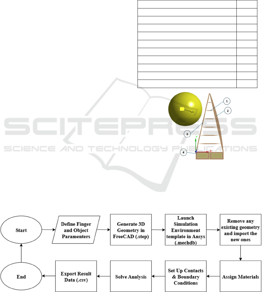
FEA simulation. The workflow (shown in Figure 2)
begins with a user defining the gripper's geometric
parameters via the web interface. These parameters
are then passed to a Free CAD scripting engine that
generates the required .step files for the components.
Subsequently, the .step files are imported by a
PyAnsys script, which automates the setup, solution,
and post-processing within Ansys Mechanical. The
final stage of the pipeline involves the script
outputting the time-dependent performance data as
CSV files, enabling quantitative comparison between
design iterations.
3.2 Parametric Design Generation via
Web Application
A web application built with the Gradio library serves
as the front-end, allowing users to define the finger's
design parameters (Table 2). These parameters are
sent to a FreeCAD script that programmatically
generates the 3D models of the finger, a target sphere,
and a base connector, which are then exported as
STEP files. For this study, a parametric analysis was
performed by varying the number of crossbeams from
1 to 16, as this is a key parameter in the Fin Ray Effect
design. All other geometric parameters, including the
50 mm sphere diameter, were held constant.
Table 2: Design parameters used by the developed
computational tool to create the Fin Ray Effect Finger.
Parameter Unit
Overall fin
g
er len
g
th [mm]
Finger base width [mm]
Fin
g
er de
p
th [mm]
Fin
g
er frame thickness [mm]
Rear frame side amplitude [mm]
Number of cross
b
eams [-]
Beam thickness [mm]
Minimum beam thickness [mm]
Taper ratio [-]
Crossbeam an
g
le [de
g
]
Figure 1: Architecture of the soft robotic finger and
simulation setup. The finger consists of (1) Crossbeams, (2)
a flexible rear spine, (3) the contact side, and (4) the finger
base. A displacement is applied to the target sphere to
simulate contact.
Figure 2: Flowchart of the automated computational workflow.
COBOTA 2025 - Special Session on Bridging the Gap in COllaborative roBOtics: from Theory to real Applications
580
3.3 Automated Finite Element Analysis
The simulation is controlled by a PyAnsys script that
automates the workflow in Ansys Mechanical. The
script begins by opening a template project, replacing
any existing geometry with the newly generated
STEP files. Materials are then assigned
programmatically, with a hyperelastic model for the
TPU 60A finger and structural steel for the other
components. The script automatically defines the
necessary frictionless and bonded contacts and
applies the boundary conditions for the linear
actuation model. The analysis uses 10-node
tetrahedral elements with contacts modelled using an
Augmented Lagrange formulation.
3.4 Material Model Characterization
The mechanical behaviour of the flexible gripper
material, TPU 60A, was determined through
experimental testing in previous works (Lang et al.,
2025). From this characterization, the stress-strain
data was used as an input for the computational
model. This experimental data was imported into
Ansys Engineering Data, where the 2nd Order
Polynomial hyperelastic model was selected for
providing the best fit (R² = 0.9993), ensuring the
simulated material behaviour reflects the real-world
performance of the 3D-printed TPU 60A.
3.5 Simulation and Post-Processing
Once the model is generated, the script initiates the
static structural analysis in Ansys Mechanical. To
analyse the gripping performance, a Contact Tool is
programmatically added to the solution and scoped
specifically to the finger-object interface. After the
solve is complete, the script automatically exports
key results, such as the Force Reaction at the finger's
base and the Contact Pressure distribution, to CSV
files for quantitative analysis. This automated data
extraction is critical for comparing the performance
of different parametric designs.
4 RESULTS
The computational tool was employed to conduct a
parametric study investigating the influence of the
number of internal crossbeams on the performance of
the FRE SRGF. A series of simulations was executed
with 1, 2, 3, 4, 6, 8, 10, 12, 14, and 16 crossbeams,
while all other geometric and simulation parameters
were held constant, as defined in the materials and
methods section. Four performance indicators—
maximum contact pressure ( 𝑃
), final reaction
force (𝐹
), average contact pressure (𝑃
)—were
recorded at the final time step of each simulation to
evaluate the gripper’s design. A pressure uniformity
ratio (𝑈
) was calculated according to Equation (1):
𝑈
𝑃
𝑃
(1)
This ratio serves as an indicator of grasping
quality. In an ideal case, the contact pressure is evenly
distributed, and the ratio approaches 1.
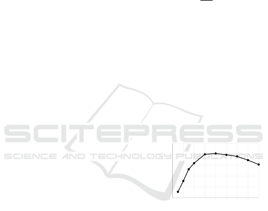
4.1 Effect on Maximum Contact
Pressure
The relationship between the number of crossbeams
and the resulting maximum contact pressure is shown
in
Figure 3
. The trend is non-linear. The maximum
pressure increases sharply from 0.03 MPa with one
crossbeam to a peak of 0.20 MPa for designs with 6,
8, and 10 crossbeams. This initial rise corresponds to
the increase in stiffness, which concentrates the
gripping force onto smaller areas. Beyond 10
crossbeams, a clear downward trend is observed, with
the maximum pressure decreasing to 0.15 MPa for the
16-crossbeam design.
𝑃
[MPa]
Number of crossbeams
Figure 3: Maximum Contact Pressure applied in the last
step of the simulation for each design configuration.
4.2 Effect on Gripping Force
The total reaction force indirectly indicates the
overall gripping force exerted by the finger and is
presented in
Figure 4
. The results show a clear and
consistent trend as the number of crossbeams
increases the reaction force steadily rises. The force
increases from 0.85 N for a single crossbeam to a
maximum of 1.67 N for the 16-crossbeam design.
This indicates that adding more crossbeams
progressively increases the structural stiffness of the
0.00
0.05
0.10
0.15
0.20
0.25
0246810121416
Automated Computational Workflow for the Parametric Design and Optimization of a 3D-Printed Fin Ray Effect Soft Robotic Finger
581
finger, allowing it to generate a stronger grip for the
same actuation displacement.
𝐹
[N]
Number of crossbeams
Figure 4: Force Reaction for each design configuration.
This condition together with the decrease of
maximum pressure after 8 crossbeams demonstrates
that a higher number of crossbeams distributes the
load more effectively, reducing the intensity of
pressure "hot spots."
4.3 Effect on Average Contact Pressure
The average contact pressure across the entire contact
patch is presented in
Figure 5
. This metric shows a
consistent upward trend, rising from 1.51 × 10
3
MPa
for a single crossbeam to a peak of 3.13 × 10
3
MPa
for the 14-crossbeam design. Unlike the maximum
pressure, the average pressure does not decrease with
a higher number of crossbeams, it is almost constant
from the 10-crossbeam design to 16-crossbeam
design. This suggests that while the peak pressures
are reduced, the overall pressure across the contact
area remains high and becomes more uniform,
indicating a more efficient and distributed grip.
𝑃
[MPa]
Number of crossbeams
Figure 5: Average Contact Pressure applied in the last step
of the simulation for each design configuration.
4.4 Effect on Pressure Distribution
Uniformity
To quantify the uniformity of the grip, the ratio of the
average pressure to the maximum pressure was
calculated. A higher ratio signifies a more evenly
distributed load. The results, plotted in Figure 6, show
that the 1-crossbeam design had an exceptionally high
uniformity ratio of 0.055, which is a consequence of
its very low stiffness that results in low reaction force
and max pressure. After this initial point, the
uniformity drops significantly, reaching a minimum
at 6 crossbeams where 𝑈
=
0.014. As more
crossbeams are added beyond this point, the pressure
distribution becomes progressively more uniform,
with the ratio steadily climbing to a new peak of 𝑈
=
0.023 for the 16-crossbeam design. This trend
suggests that a high number of crossbeams
contributes to achieving an even and gentle grip.
𝑈
[-]
Number of crossbeams
Figure 6: Ratio between Average Contact Pressure and
Maximum Contact Pressure in each configuration as an
evaluation parameter for pressure distribution.
4.5 Visual Analysis of Contact Pressure
Maps
To visualize the qualitative trends underlying the
quantitative data, Figure 7 displays the
contact‑pressure maps for four representative designs
containing 2, 6, 10 and 14 cross‑beams.
2 crossbeams (Figure 7a) – A narrow, vertically
aligned band of increased contact pressure is observed.
Local peaks occur where the lower crossbeam touches
the object and at the fingertip, whereas a small zone in
the top region shows lower contact pressure. The
contact area is therefore large, but the finger is
compliant and offers limited grasping stiffness, as
indicated by the narrow contact region.
6 crossbeams (Figure 7b) – The pressure field
becomes broader and lower. A zone of low pressure
appears from mid‑height to near the top, bounded by
a second cross‑beam footprint. A pronounced
0.50
0.75
1.00
1.25
1.50
1.75
0246810121416
0.001
0.0015
0.002
0.0025
0.003
0.0035
0 2 4 6 8 10 12 14 16
0
0.01
0.02
0.03
0.04
0.05
0.06
0246810121416
COBOTA 2025 - Special Session on Bridging the Gap in COllaborative roBOtics: from Theory to real Applications
582
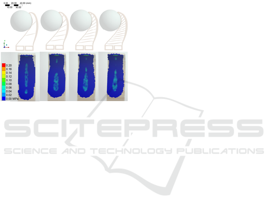
pressure peak appears at the fingertip, indicating a
configuration that may damage delicate objects.
As the number of crossbeams further increases to
10 (Figure. 7c) and 14 (Fig. 7d), the contact area
continues to expand, and the load distribution
becomes more uniform. Crucially, this reduces the
maximum pressure at the fingertip, leading to a more
stable and gentler grasp.
(a) (b) (c) (d)
Figure 7: Finger Deformation and Contact Pressure Map at
the end of the simulation for different number o
f
crossbeams in the design, a) 2, b) 6, c) 10, d) 14.
Adding crossbeams initially raises the local peak
pressure at the fingertip but further increases
progressively equalise the pressure over the finger,
reducing the peak value and improving grasp quality
while maintaining adequate stiffness.
5 CONCLUSIONS
In this work, a comprehensive computational tool for
the design and optimization of a 3D-printed, Fin Ray
Effect robotic gripper was developed and validated.
By integrating a parametric web interface with a
FreeCAD geometry engine and a PyAnsys-driven
finite element analysis backend, a closed-loop digital
thread was created, enabling the rapid iteration and
quantitative evaluation of different gripper designs.
The parametric study, which varied the number of
internal crossbeams from 1 to 16
(1,2,3,4,6,8,10,12,14,16), revealed a complex and
non-linear relationship between number of
crossbeams and gripping performance. The results
demonstrate that the relation between contact
pressure, maximum pressure and grasping quality is
not linear. Designs with 6 to 10 crossbeams exhibited
a higher maximum contact pressure but at the cost of
a poor pressure uniformity, characterized by a
pressure peak near the fingertip. Conversely, designs
with a high number of crossbeams (above 14) showed
a marked improvement in performance in terms of
pressure distribution. These configurations reduced
the maximum contact pressure while simultaneously
increasing the pressure distribution uniformity. The
visual analysis of the contact pressure maps provided
a qualitative confirmation of these findings,
illustrating the transition from a focused, high-
pressure grip to a more compliant and evenly
distributed grip as the number of crossbeams was
increased. Based on the simulation data, it can be
concluded that for applications where minimizing
pressure to a gripped object’s surface is essential, a
design with a higher number of crossbeams (e.g., 14-
16) represents an optimal solution. This configuration
provides a balance of a low maximum pressure, a
bigger gripping force and a uniform pressure
distribution.
Future work will investigate additional
parameters influencing the performance of FRE
SRGF, including crossbeam angles and material
selection. Additionally, the fingertip design must be
reevaluated to mitigate the maximum pressure
hotspot and improve delicate object handling.
ACKNOWLEDGEMENTS
These results are within the research activities of
project “ROBOTA-SUDOE - Robotics, Automation,
and Digitalization as Drivers of Competitiveness and
Growth for SMEs” (S1/1.1/P0125), which is co-
funded by the European Union through the European
Regional Development Fund (ERDF) and national
funds, under the territorial cooperation Interreg
Europe Programme 2021–2027 (eSUDOE 2021-
2027). This research was partially funded by the
Portuguese Foundation for Science and Technology,
I.P. (FCT, I.P.) FCT/MCTES through national funds
(PIDDAC), under the R&D Unit C-MAST/Center for
Mechanical and Aerospace Science and
Technologies, reference: Projects UIDB/00151/2020
(https://doi.org/10.54499/UIDB/00151/2020) and
UIDP/00151/2020
(https://doi.org/10.54499/UIDP/00151/2020)
Automated Computational Workflow for the Parametric Design and Optimization of a 3D-Printed Fin Ray Effect Soft Robotic Finger
583

REFERENCES
ANSYS Inc. (2017). Appendix 4A: Hyperelasticity.
Connolly, F., Polygerinos, P., Walsh, C. J., & Bertoldi, K.
(2015). Mechanical programming of soft actuators by
varying fiber angle. Soft Robotics, 2(1), 26–32.
Dassault Systèmes. (2018). Modeling Rubber and
Viscoelasticity with Abaqus.
Elgström, E. (2014). Practical implementation of
hyperelastic material methods in FEA models.
Garcia, M., Esquen, A.-C., Sabbagh, M., Grace, D.,
Schneider, E., Ashuri, T., Voicu, R. C., Tekes, A., &
Amiri Moghadam, A. A. (2024). Soft Robots:
Computational Design, Fabrication, and Position
Control of a Novel 3-DOF Soft Robot. Machines, 12(8),
539.
Guo, M., & Hesthaven, J. S. (2018). Reduced order
modeling for nonlinear structural analysis using
Gaussian process regression. Computer Methods in
Applied Mechanics and Engineering, 341, 807–826.
https://doi.org/10.1016/J.CMA.2018.07.017
Han, Y., Duan, J., & Wang, S. (2020). Benchmark problems
of hyper-elasticity analysis in evaluation of FEM.
Materials, 13(4), 885.
Jin, J., Feng, S., & Li, S. (2024). Computational Design of
Customized Vacuum-Driven Soft Grippers. IEEE
Robotics and Automation Letters.
Lang, L., Antunes, R., Dutra, T. A., Aguiar, M. L. de,
Pereira, N., & Gaspar, P. D. (2025). Mechanical
Characterization and Computational Analysis of TPU
60A: Integrating Experimental Testing and Simulation
for Performance Optimization. Materials, 18(2).
https://doi.org/10.3390/ma18020240
Liu, S. Q., & Adelson, E. H. (2022). GelSight Fin Ray:
Incorporating Tactile Sensing into a Soft Compliant
Robotic Gripper. http://arxiv.org/abs/2204.07146
Liu, S. Q., Ma, Y., & Adelson, E. H. (2023). GelSight Baby
Fin Ray: A Compact, Compliant, Flexible Finger with
High-Resolution Tactile Sensing.
http://arxiv.org/abs/2303.14883
Maronehitz, P. (2024). Scripting for Mechanical Engineers.
Megan, L., & Croop, B. (2014). A Mechanism for the
Validation of Hyperelastic Materials in ANSYS.
Datapointlabs.
Navez, T., Ménager, E., Chaillou, P., Goury, O.,
Kruszewski, A., & Duriez, C. (2025). Modeling,
Embedded Control and Design of Soft Robots using a
Learned Condensed FEM Model. IEEE Transactions on
Robotics.
Nonaka, T., Abdulali, A., Sirithunge, C., Gilday, K., & Iida,
F. (2023). Soft robotic tactile perception of softer
objects based on learning of spatiotemporal pressure
patterns. 2023 IEEE International Conference on Soft
Robotics, RoboSoft 2023.
https://doi.org/10.1109/ROBOSOFT55895.2023.1012
1950
Ponce, H., Mart\’\inez-Villaseñor, L., & Mayorga-Acosta,
C. (2021). Design of a soft gripper using genetic
algorithms. Computación y Sistemas, 25(4), 835–842.
Shin, J. H., Park, J. G., Kim, D. Il, & Yoon, H. S. (2021). A
Universal Soft Gripper with the Optimized Fin Ray
Finger. International Journal of Precision Engineering
and Manufacturing - Green Technology, 8(3), 889–899.
https://doi.org/10.1007/s40684-021-00348-1
Stella, F., & Hughes, J. (2023). The science of soft robot
design: A review of motivations, methods and enabling
technologies. Frontiers in Robotics and AI, 9, 1059026.
Suder, J., Bobovský, Z., Mlotek, J., Vocetka, M., Oščádal,
P., & Zeman, Z. (2021). Structural optimization method
of a finray finger for the best wrapping of object.
Applied Sciences (Switzerland), 11(9).
https://doi.org/10.3390/app11093858
Xie, Y., Pinskier, J., Liow, L., Howard, D., & Iida, F.
(2024). A’MAP’to find high-performing soft robot
designs: Traversing complex design spaces using
MAP-elites and Topology Optimization. 2024
IEEE/RSJ International Conference on Intelligent
Robots and Systems (IROS), 11408–11415.
Xie, Y., Wang, X., Iida, F., & Howard, D. (2024). Fin-QD:
A Computational Design Framework for Soft Grippers:
Integrating MAP-Elites and High-fidelity FEM. 2024
IEEE 7th International Conference on Soft Robotics,
RoboSoft 2024, 692–697.
https://doi.org/10.1109/ROBOSOFT60065.2024.1052
1959.
Yi, S., Bai, X., Singh, A., Ye, J., Tolley, M. T., & Wang, X.
(2025). Co-Design of Soft Gripper with Neural Physics.
ArXiv Preprint ArXiv:2505.20404.
Zhang, C., Zhu, P., Lin, Y., Jiao, Z., & Zou, J. (2020).
Modular soft robotics: Modular units, connection
mechanisms, and applications. Advanced Intelligent
Systems, 2(6), 1900166.
COBOTA 2025 - Special Session on Bridging the Gap in COllaborative roBOtics: from Theory to real Applications
584
