Preliminary Design and Control of an Operator-Assistance System
Integrated into a Cobot, for Anatomical Meat-Cutting Process
Alexis Babut
a
, Chedli Bouzgarrou
b
, Laurent Sabourin
c
and Nicolas Bouton
d
Universit
´
e Clermont Auvergne, Clermont Auvergne INP, CNRS, Institut Pascal
F-63000 Clermont-Ferrand, France
Keywords:
Operator Assistance System, Collaborative Robot, Compliant Control, Physical Human–Robot Interaction.
Abstract:
This paper presents the preliminary design and control of a collaborative robotic cell for operator assistance
in tasks involving soft material manipulation, such as meat cutting. The system integrates force/torque sen-
sors and employs a Cartesian admittance controller to enable compliant, intuitive physical interaction. The
mechanical design of the end-effector, the control architecture, and the communication strategy are described.
Initial experiments validate the system’s ability to provide stable and responsive assistance in a physical Hu-
man–Robot Interaction (pHRI) context.
1 INTRODUCTION
While automation continues to progress across many
sectors, some manual tasks remain difficult to mecha-
nise due to their complexity, variability and reliance
on human dexterity. This is especially the case in
the meat industry, which faces a labour shortage and
low job attractiveness. Workers are also exposed to
physically demanding conditions, including repetitive
movements, awkward postures and fast-paced work-
flows.
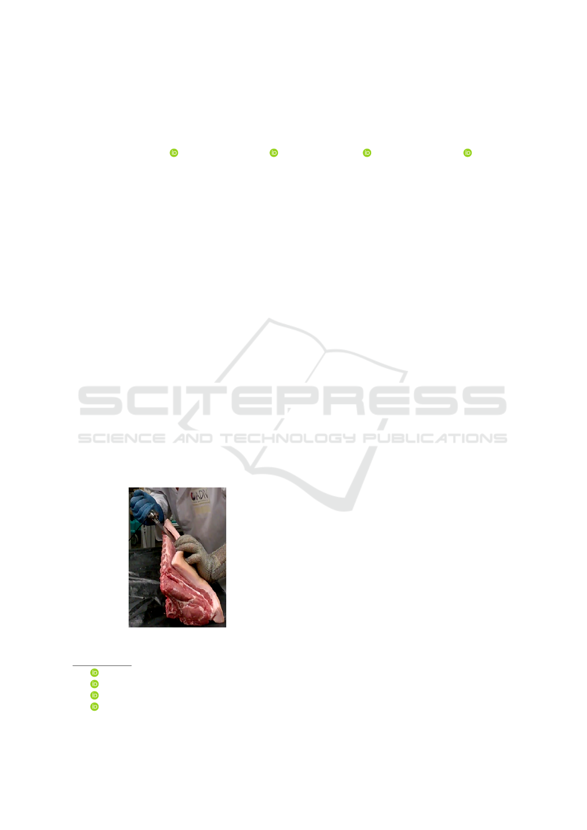
Figure 1: Manual meat-cutting performed by a human op-
erator.
a
https://orcid.org/0009-0005-2749-1422
b
https://orcid.org/0000-0003-2394-1770
c
https://orcid.org/0000-0002-7840-9186
d
https://orcid.org/0000-0001-5673-5979
Among the various tasks performed in this sec-
tor, anatomical meat cutting is particularly critical and
complex. It requires fine motor skills, adaptability
and force regulation, making it especially resistant
to full automation. To achieve complete mechanisa-
tion, complex physical models would need to be de-
veloped and computed in real time, which remains
a significant technological challenge. Consequently,
the choice of an assistance approach using a collabo-
rative robotic system is being considered.
In recent years, collaborative robots (cobots) have
become essential tools in industrial and service ap-
plications requiring physical human-robot interaction
(pHRI). Unlike traditional robots confined to isolated
workspaces, cobots operate alongside humans, requir-
ing advanced strategies to ensure safety, adaptabil-
ity and intuitive control (Farajtabar and Charbonneau,
2024) (Ajoudani et al., 2017).
Tasks involving deformable or soft objects, such
as in meat processing, pose particular challenges for
pHRI due to the unpredictable nature of soft mate-
rials and variable human-applied forces. Conven-
tional position or force control methods often fall
short in achieving both compliant and robust behav-
ior (Keemink et al., 2018).
Impedance and admittance control schemes ad-
dress these challenges by regulating the dynamic in-
teraction between motion and force. Introduced by
Hogan (Hogan, 1984), impedance control is suited to
motion-driven tasks, while admittance control excels
when motion results from external forces, making it
Babut, A., Bouzgarrou, C., Sabourin, L. and Bouton, N.
Preliminary Design and Control of an Operator-Assistance System Integrated into a Cobot, for Anatomical Meat-Cutting Process.
DOI: 10.5220/0013928400003982
Paper published under CC license (CC BY-NC-ND 4.0)
In Proceedings of the 22nd International Conference on Informatics in Control, Automation and Robotics (ICINCO 2025) - Volume 2, pages 541-551
ISBN: 978-989-758-770-2; ISSN: 2184-2809
Proceedings Copyright © 2025 by SCITEPRESS – Science and Technology Publications, Lda.
541
especially useful for cooperative scenarios (Keemink
et al., 2018) (Sharkawy and Koustoumpardis, 2022).
During meat-cutting operations, the operator typi-
cally applies significant and variable forces on the tool
depending on tissue consistency and cutting direction.
Accurately estimating and responding to these forces
is essential for delivering effective and safe robotic
assistance.
This work presents a Cartesian admittance-based
assistance system integrated into a collaborative
robotic cell. The system is equipped force/torque sen-
sors for estimating user-applied efforts, enabling real-
time compliant motion through a human-centred con-
trol interface.
The remainder of the paper is structured as fol-
lows: Section 2 introduces the robotic cell and tool
design. Section 3 describes the control strategy and
force estimation method. Section 5 presents exper-
imental results, and Section 6 concludes with a dis-
cussion and future directions.
2 OVERVIEW OF THE ROBOTIC
CELL
This section introduces the overall architecture and
key components of the robotic cell. It details the robot
platform, the design of the instrumented tool includ-
ing its sensing capabilities, and the communication
infrastructure that connects all parts of the system.
2.1 System Architecture
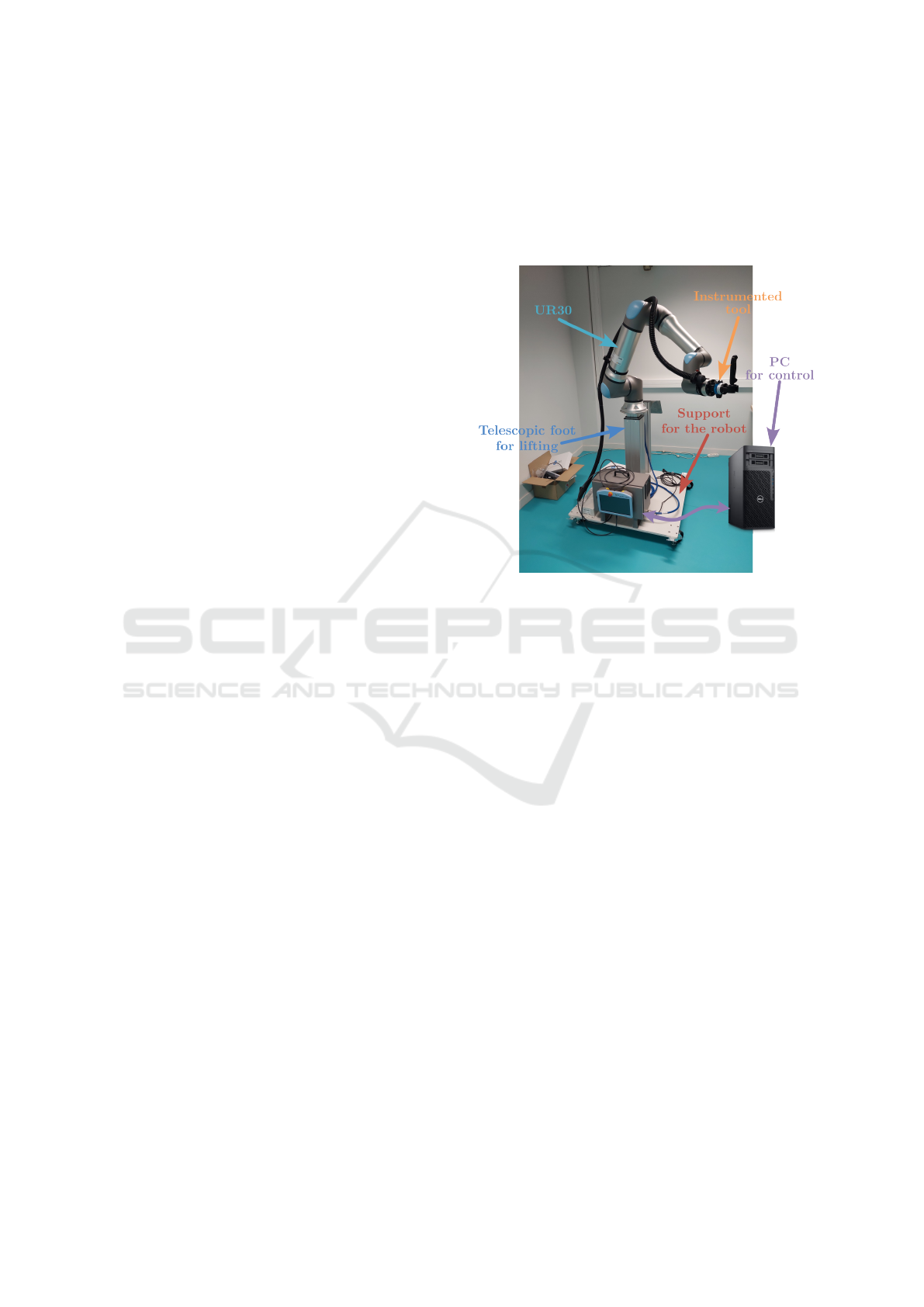
The robotic cell is built around a 6-axis UR30 col-
laborative robot (Universal Robots), mounted on a
telescopic pillar (LIFTKIT-UR-620). The UR30 was
selected for its high payload capacity (up to 30 kg)
and compact form factor, which make it particularly
suitable for force-intensive tasks such as meat cut-
ting, where strength, precision and operator safety are
essential. Its collaborative design allows safe inter-
action with human operators, while maintaining the
flexibility required for complex trajectories in con-
strained environments.
The robot is controlled by a real-time Linux-based
computer, and the system integrates sensing, control,
and perception modules to enable accurate tracking
of interactions and responsive behaviour. Communi-
cation between the robot and the control computer is
established through an Ethernet cable.
The robot’s end-effector is equipped with a multi-
sensor instrumented tool, composed of a handle and a
blade, designed for precise interaction measurement.
To perceive the environment, the setup includes a 3D
vision system (StereoLabs Robotics 360 Perception
Kit) and a motion tracking system (Movella MTw
Awinda Research Bundle), which provide real-time
scene analysis and track the human operator’s pose.
These perception systems are not yet employed in the
current study.
Figure 2: Overview of the robotic cell.
2.2 Design of the Instrumented Knife
This part presents the design of the instrumented tool
mounted on the robot’s end-effector, with a focus on
its force/torque sensing capabilities and mechanical
integration. The tool is intended to precisely measure
interaction forces exerted by both the operator and the
manipulated object.
2.2.1 Sensor Integration Prototypes
Force/torque sensors are integrated within the tool as-
sembly to accurately capture interaction forces. The
primary sensor employed is the BOTA Systems Sen-
sONE T15, selected for its high measurement preci-
sion and reliable communication performance. This
sensor measures all forces applied to the mounted tool
and provides better accuracy than the robot’s internal
force/torque sensor.
A custom mechanical adapter was designed to
connect the SensONE sensor to the UR30 robot’s
tool flange. This adapter is manufactured using
Fused Deposition Modelling (FDM) with carbon-
fibre-reinforced Nylon (PA-CF), combining strength
and lightweight properties.
Because two distinct forces act on the tool, the
force applied by the human operator and the reac-
tion force from the product, using only one sensor
COBOTA 2025 - Special Session on Bridging the Gap in COllaborative roBOtics: from Theory to real Applications
542
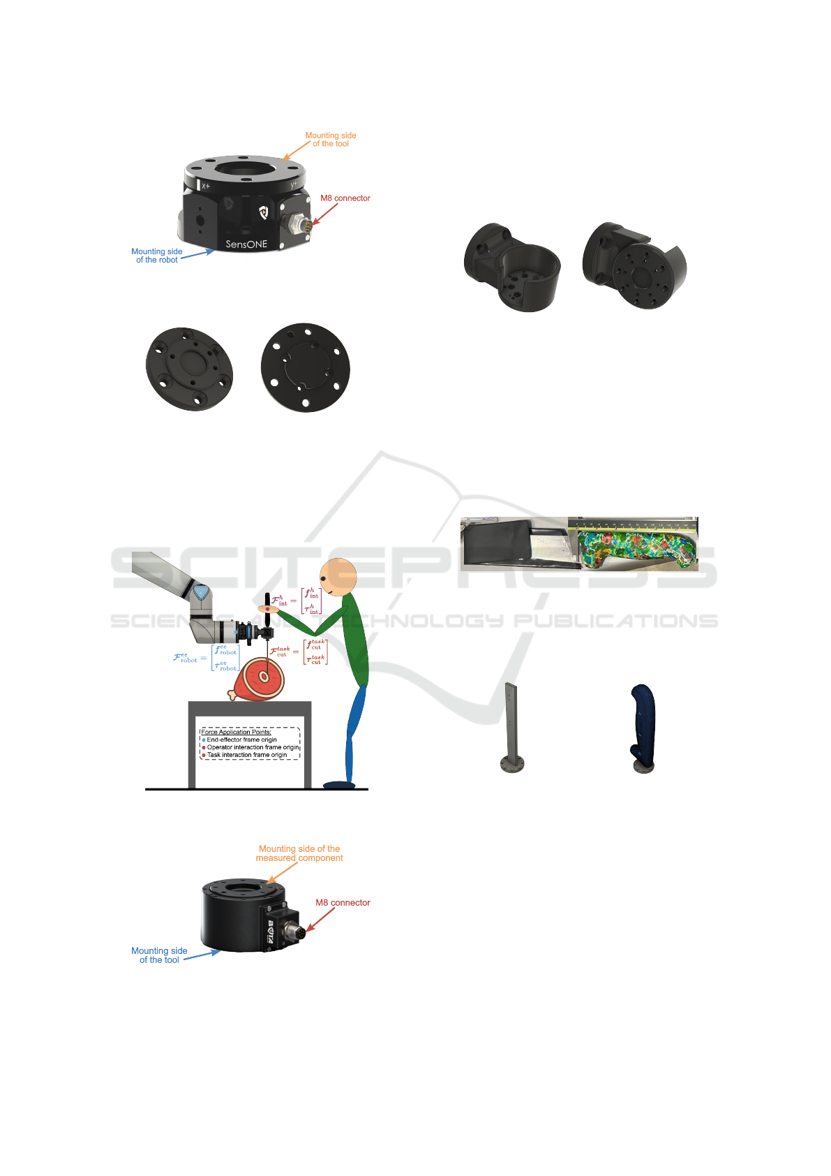
Figure 3: BOTA Systems SensONE T15 force/torque sen-
sor.
(a) Sensor side (b) Robot side
Figure 4: SensONE to UR30 adapter.
will capture their combined effect without distinction.
Therefore, a second force/torque sensor, the BOTA
Systems Medusa, is required to independently mea-
sure and separate these forces.
Figure 5: Forces applied on the tool during a meat-cutting
task with a robot.
Figure 6: BOTA Systems Medusa force/torque sensor.
The Medusa sensor is mounted using a dedicated
adapter, also printed in PA-CF using FDM. A modular
design enables different assembly configurations, al-
lowing the measurement of forces at either the handle
or the blade.
(a) Top view (b) Bottom view
Figure 7: Second force/torque sensor adapter.
2.2.2 Knife Prototypes
The knife handle was modelled from a 3D scan of a
real industrial knife, commonly used in meat process-
ing. This scan served as a realistic basis for designing
functional handle prototypes, which were manufac-
tured using PLA filament through FDM (Fused De-
position Modeling) 3D printing.
Figure 8: Industrial knife used as design reference.
To ensure mechanical robustness, the PLA handle
is mounted on a welded steel substructure that serves
as the structural backbone of the tool. This interface
guarantees stability during high-force interactions.
(a) Steel connector (b) Assembled handle
Figure 9: Knife handle of the tool prototypes.
A push-button is integrated into the handle and
connected to an analogue input on the UR30 control
box. This button allows the operator to manually trig-
ger the robot’s compliant motion, offering intuitive in-
teraction during collaborative tasks.
Finally, the complete assembly is mounted using
a tool changer on the robot flange, as shown in Figure
10.
Preliminary Design and Control of an Operator-Assistance System Integrated into a Cobot, for Anatomical Meat-Cutting Process
543
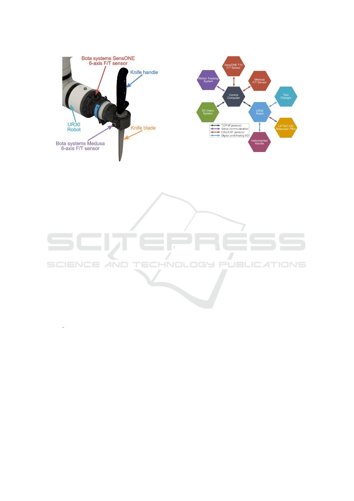
Figure 10: Tool assembly mounted on the robot tool flange.
2.3 Communication Setup
The robotic cell relies on a real-time communica-
tion architecture linking the control unit to all sen-
sors and actuators. The UR30 robot communicates
with the control computer through an Ethernet (RJ45)
connection using the TCP/IP protocol. The BOTA
Systems force/torque sensors, including the SensONE
and Medusa models, operate over the EtherCAT pro-
tocol. They are powered using Power-over-Ethernet
(PoE), and sensor data is transmitted to the computer
through the LAN output of the PoE injector.
The 3D vision system is connected to the con-
trol computer through Ethernet using the TCP/IP pro-
tocol. The motion tracking system (Xsens Awinda)
communicates with the computer through a dedicated
USB interface using a virtual COM port (serial pro-
tocol). The tool changer is electrically linked to
the robot’s tool flange I/O, while the telescopic pil-
lar is connected to the control box USB port. Both
are monitored in the ROS2 environment through the
/robot
states topic.
3 CONTROL STRATEGY
This section presents the control strategy developed
for the robotic cell. Due to the limitations of the
Universal Robot interface, control commands are re-
stricted to joint positions or joint velocities. There-
fore, implementing a torque-based control scheme is
not possible, and the control architecture must be de-
signed to accommodate these constraints.
The main objective is to achieve smooth and trans-
parent interaction between the human and the robot in
all directions, including rotation. The robot must re-
Figure 11: Communication architecture of the robotic cell.
spond naturally to the operator’s guidance, allowing
for intuitive and safe cooperation throughout shared
tasks.
In addition to enabling compliant motion, it is nec-
essary to regulate the cutting force applied by the tool.
The control system must implement a force amplifica-
tion strategy, where the cutting force in the task frame
is saturated as F
F
F
task
cut
= k ·F
F
F
h
int
3.1 Overview of Admittance Control
The aim of compliant control is to generate the robot’s
movement by emulating a mass-spring-damper sys-
tem behaviour (Keemink et al., 2018) as illustrated in
Figure 13.
Admittance control computes the robot’s displace-
ment x
r
∈ R
m
in response to external forces F
F
F
ext
∈
R
m
, where m = 6 in our case, corresponding to Carte-
sian space. This relationship is modelled using a
mass–spring–damper system equation:
M
dx
(
¨
x
r
−
¨
x
d
) + D
dx
(
˙
x
r
−
˙
x
d
)
+K
dx
(x
r
− x
d
) = F
F
F
ext
(1)
Here, M
dx
, D
dx
, and K
dx
are the desired Cartesian
inertia, damping, and stiffness matrices respectively,
while x
d
,
˙
x
d
, and
¨
x
d
denote the desired Cartesian tra-
jectory position, velocity, and acceleration.
Using equation 1, the Cartesian acceleration re-
sulting from the applied external forces can be ex-
pressed as:
¨
x
r
=
¨
x
d
+ M
−1
dx
h
F
F
F
ext
− D
dx
(
˙
x
r
−
˙
x
d
)
−K
dx
(x
r
− x
d
)
i
(2)
After double integration, the resulting Cartesian
position error e
x
= x
r
− x
d
is tracked by a joint-level
control loop, typically handled by the robot’s internal
COBOTA 2025 - Special Session on Bridging the Gap in COllaborative roBOtics: from Theory to real Applications
544
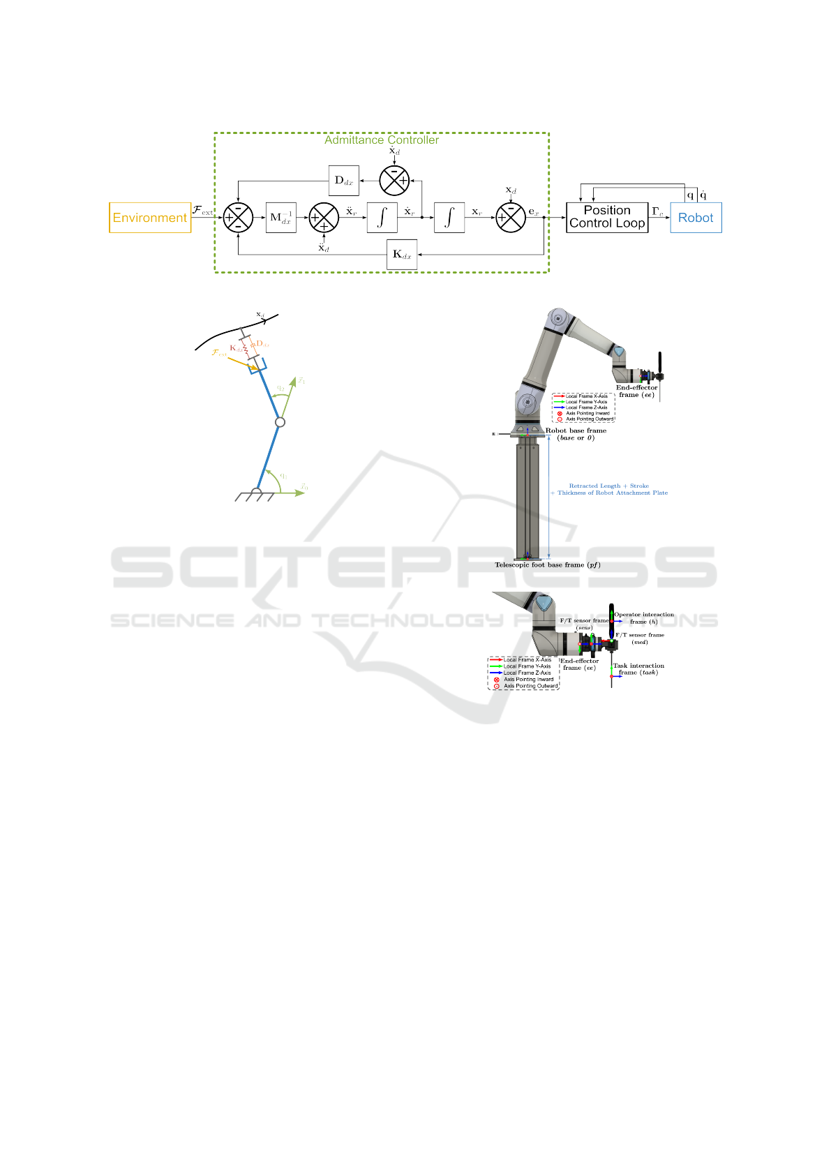
Figure 12: Block diagram of Cartesian admittance control.
Figure 13: Schematic of the robot’s compliant model prin-
ciple.
controller. If the robot’s dynamics are known, an in-
verse dynamics model combined with a feedback con-
troller (such as PID or PD) can be used to regulate the
joint motion and follow the reference trajectory. The
resulting control torques Γ
Γ
Γ
c
are applied to the robot’s
actuators, as illustrated in Figure 12.
3.2 System Coordinate Frames
Accurate control and interpretation of sensor data re-
quire a defined set of coordinate frames for the robot,
the tool, and the associated sensors. These frames
serve as spatial references for motion planning, force
estimation, and control execution. Figure 14 shows an
overview of the coordinate frames of the robotic sys-
tem, including the robot base frame, individual joint
frames, and the end-effector frame.
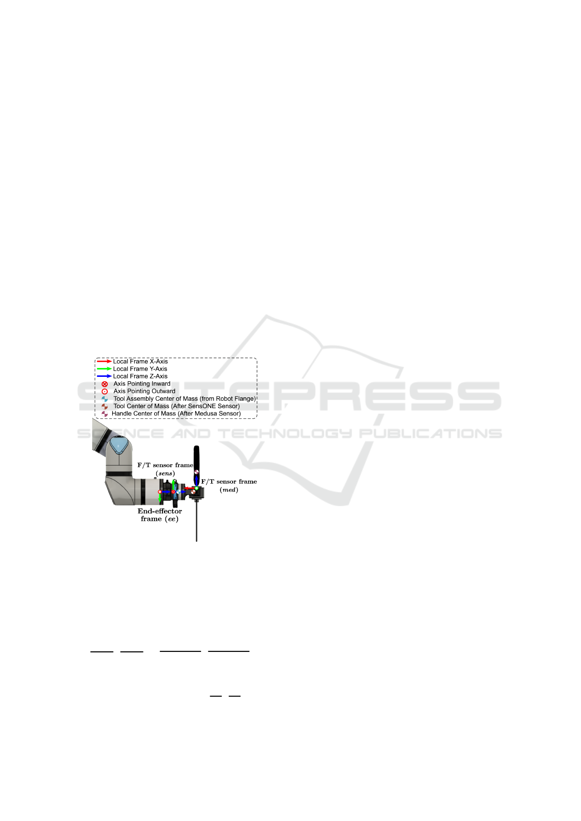
3.3 Estimation of Human-Applied
Forces
To estimate the forces applied by the human operator
on the handle, a six-axis force/torque sensor (Medusa)
is mounted directly on the handle. This sensor mea-
sures the interaction forces transmitted through the
handle. The method presented here is used to iden-
tify the sensor bias and recover the true force exerted
by the operator. The same procedure is applied to
(a) Overview of robotic system
(b) Robot end-effector and tool
Figure 14: Coordinate frames defined for the Robotic sys-
tem.
the primary force/torque sensor (SensONE), which is
mounted on the robot tool flange thanks to an adapter
piece, to estimate external forces acting on the tool.
3.3.1 Bias and Handle Parameter Identification
Force/torque sensors typically have intrinsic bias,
causing non-zero output even when no external load
is applied. This bias can result from installation
preloads, component weight, or dynamic effects dur-
ing motion.
Under static conditions without external contact
forces, the sensor output mainly reflects the bias and
the gravitational force due to the handle’s mass. The
handle’s mass m
ha
is measured beforehand using a
Preliminary Design and Control of an Operator-Assistance System Integrated into a Cobot, for Anatomical Meat-Cutting Process
545
precision scale and then introduced in the identifica-
tion process. The sensor output is modelled as:
f
f
f
med
measured
= f
f
f
med
bias
+ m
ha
g
med
τ
τ
τ
med
measured
= τ
τ
τ
med
bias
− m
ha
med
P
CoM
× g
med
(3)
Here, f
f
f
med
bias
and τ
τ
τ
med
bias
denote the constant force and
torque sensor biases, m
ha
is the mass of the handle,
and
med
P
CoM
is the position vector from the sensor
origin to the handle’s centre of mass, expressed in the
sensor frame, as illustrated in Figure 15. The vec-
tor g
med
represents the gravity vector expressed in the
sensor frame, computed from the gravity vector in the
robot base frame:
g
base
=
0 0 −9.81
T
m/s
2
Given
ee
A
med
as the rotation matrix of the sensor
relatively to the end-effector frame, and
base
A
ee
as the
end-effector orientation in the base frame, the gravity
vector in the sensor frame is given by:
g
med
=
base
A
ee
ee
A
med
T
g
base
(4)
Figure 15: Sensor frames and tool center of mass.
For each static pose i, the measurements satisfy
the linear system:
f
f
f
med
1
− m
ha
g
med
1
τ
τ
τ
med
1
.
.
.
f
f
f
med
N
− m
ha
g
med
N
τ
τ
τ
med
N
| {z }
b∈R
6N
=
I
3
0
3×3
0
3×3
0
3×3
I
3
−m
ha
[g
med
1
]
×
.
.
.
.
.
.
.
.
.
I
3
0
3×3
0
3×3
0
3×3
I
3
−m
ha
[g
med
N
]
×
| {z }
A∈R
6N×9
·
f
f
f
med
bias
τ
τ
τ
med
bias
med
P
CoM
| {z }
X∈R
9
(5)
Here, [g
med
i
]
×
is the skew-symmetric matrix asso-
ciated with the gravity vector at pose i, in the sen-
sor frame. Using measurements from N static poses,
this overdetermined system is solved thanks to least
squares to identify unknown parameters:
X = (A
T
A)
−1
A
T
b (6)
3.3.2 Gravity Compensation
After estimating bias, handle mass, and centre of
mass, sensor outputs are compensated to isolate the
human-applied forces.
The sensor orientation relative to the base frame
is
base
A
med
, and the gravity vector in the sensor frame
is:
g
med
=
base
A
med
T
g
base
(7)
The gravitational force and moment on the sensor
are:
f
f
f
med
gravity
= m
ha
g
med
τ
τ
τ
med
gravity
=
med
P
CoM
× f
f
f
med
gravity
(8)
The compensated force and moment in the sensor
frame are then:
f
f
f
med
ext
= f
f
f
med
measured
− f
f
f
med
bias
− f
f
f
med
gravity
τ
τ
τ
med
ext
= τ
τ
τ
med
measured
−τ
τ
τ
med
bias
−τ
τ
τ
med
gravity
(9)
The resulting vector F
F
F
med
ext
=
h
f
f
f
med
ext
T
τ
τ
τ
med
ext
T
i
T
∈ R
6
represents the force and
torque applied by the human operator, expressed in
the sensor frame and compensated for sensor bias
and gravitational effects.
3.4 Compliant Control
Once the force applied by the human operator has
been estimated according to Equation 9, it is first ex-
pressed in the operator frame h (see Equation 10),
which is attached to the handle and defines the hu-
man–tool interaction interface (see Figure 14).
F
F
F
h
int
=
"
f
f
f
h
int
τ
τ
τ
h
int
#
=
med
A
h
0
3×3
med
P
h
×
med
A
h
med
A
h
F
F
F
med
ext
(10)
Here,
med
A
h
denotes the rotation matrix of the
interaction frame h to the sensor frame (med), and
med
P
h
is the position vector of the origin of frame h
expressed in the sensor frame.
Rather than using on position control, the control
strategy presented in this section is based on velocity
control, which is more appropriate for the dynamic
characteristics of the intended task. In the same way,
COBOTA 2025 - Special Session on Bridging the Gap in COllaborative roBOtics: from Theory to real Applications
546

an admittance-based control law is used to compute
the Cartesian velocity in response to external forces
applied by the human operator.
The desired Cartesian velocity is obtained
by integrating the acceleration generated by a
mass–spring–damper model, as defined in Equation 2.
This velocity determines how the robot should move
within the task space in order to respond compliantly
to the operator’s efforts. It is initially computed in the
operator frame h and then transformed into the robot
end-effector frame, as shown in Equation 11.
˙
x
ee
r
=
v
ee
r
ω
ee
r
=
ee
A
h
−
ee
A
h
[
h
P
ee
]
×
0
3×3
ee
A
h
| {z }
Ad
ee
T
h
∈R
6×6
˙
x
h
r
(11)
Here,
˙
x
h
r
=
h
v
h
r
T
ω
h
r
T
i
T
denotes the com-
pliant motion resulting from the control law, ex-
pressed in the interaction (operator) frame h. The ro-
tation matrix
ee
A
h
represents the orientation of frame
h with respect to the robot end-effector frame. The
vector
h
P
ee
represents the position of the end-effector
origin expressed in frame h, and [
h
P
ee
]
×
denotes its
skew-symmetric matrix. The full matrix multiplying
˙
x
h
r
corresponds to the adjoint transformation Ad
ee
T
h
,
which maps spatial velocity (twists) from the interac-
tion frame to the robot end-effector frame.
The resulting Cartesian velocity, now expressed
in the end-effector frame, is mapped to joint veloci-
ties
˙
q
c
using the inverse of the robot Jacobian
0
J
−1
ee
.
These joint velocity commands are subsequently sent
to the low-level joint velocity controller of the robot
for execution.
3.4.1 Example of a Compliant Motion
As an initial implementation, a simple compliant con-
trol scheme was developed based on the general form
of the admittance equation, given in Equation 12:
¨
x
h
r
= M
−1
dx
F
F
F
h
int
− D
dx
˙
x
h
r
(12)
In this formulation, M
dx
and D
dx
denote the de-
sired Cartesian inertia and damping matrices, respec-
tively. The variables
¨
x
h
r
and
˙
x
h
r
represent the resulting
Cartesian acceleration and velocity in the interaction
frame h.
In this case, the stiffness matrix K
dx
is set to the
zero matrix 0
6×6
, which means that the stiffness effect
typically present in admittance control is removed.
Consequently, the robot motion corresponds to dis-
placement induced purely by the operator’s interac-
tion force, without any restoring force pulling the
robot back towards a desired or initial position x
d
.
The control parameters used in this implementa-
tion are as follows:
M
dx
=
15.0 0 0 0 0 0
0 15.0 0 0 0 0
0 0 15.0 0 0 0
0 0 0 0.4 0 0
0 0 0 0 0.4 0
0 0 0 0 0 0.4
D
dx
=
30.0 0 0 0 0 0
0 30.0 0 0 0 0
0 0 30.0 0 0 0
0 0 0 0.8 0 0
0 0 0 0 0.8 0
0 0 0 0 0 0.8
4 ROS2 ENVIRONMENT
The control environment was implemented in ROS2
and configured with a single force/torque sensor
(Medusa). The UR ROS2 driver package and all re-
lated nodes operated at 500 Hz, matching the robot’s
internal control loop. The dedicated node for the
Medusa sensor ran at 800 Hz, with measurements in-
terpolated in the compliant control node to align with
the robot control frequency.
The system architecture, shown in Figure 17, in-
cluded three main ROS2 nodes. The F/T Sensor
Medusa node published sensor data, filtered inter-
nally by the sensor with a built-in cutoff frequency,
to the compliant control node, while also interfacing
with the EtherCAT reader Python script through an
internal TCP socket. The Compliant Control node
subscribed to the sensor data and published the end-
effector target velocity. Finally, the Cartesian Velocity
Controller node computed joint velocity commands,
which were transmitted to the UR ROS2 driver for
execution by the UR30 robot.
System-level optimisation included CPU isola-
tion and real-time scheduling in FIFO mode. Dy-
namic memory allocation was reduced and computa-
tional cost minimised, providing more deterministic
behaviour compared with standard implementations.
Sensor initialisation and setup were carried out
through dedicated safety routines, triggered manu-
ally from the terminal. In this configuration, only the
built-in safety functions of the UR30 robot were en-
abled. Future extensions will integrate external safety
layers, including 3D vision. The Cartesian velocity
controller also accounted for the robot’s maximum
joint velocity and torque limits, saturating commands
when necessary to prevent unsafe execution.
Jitter, which quantifies the variability of the con-
trol loop period, can be expressed as the difference
Preliminary Design and Control of an Operator-Assistance System Integrated into a Cobot, for Anatomical Meat-Cutting Process
547
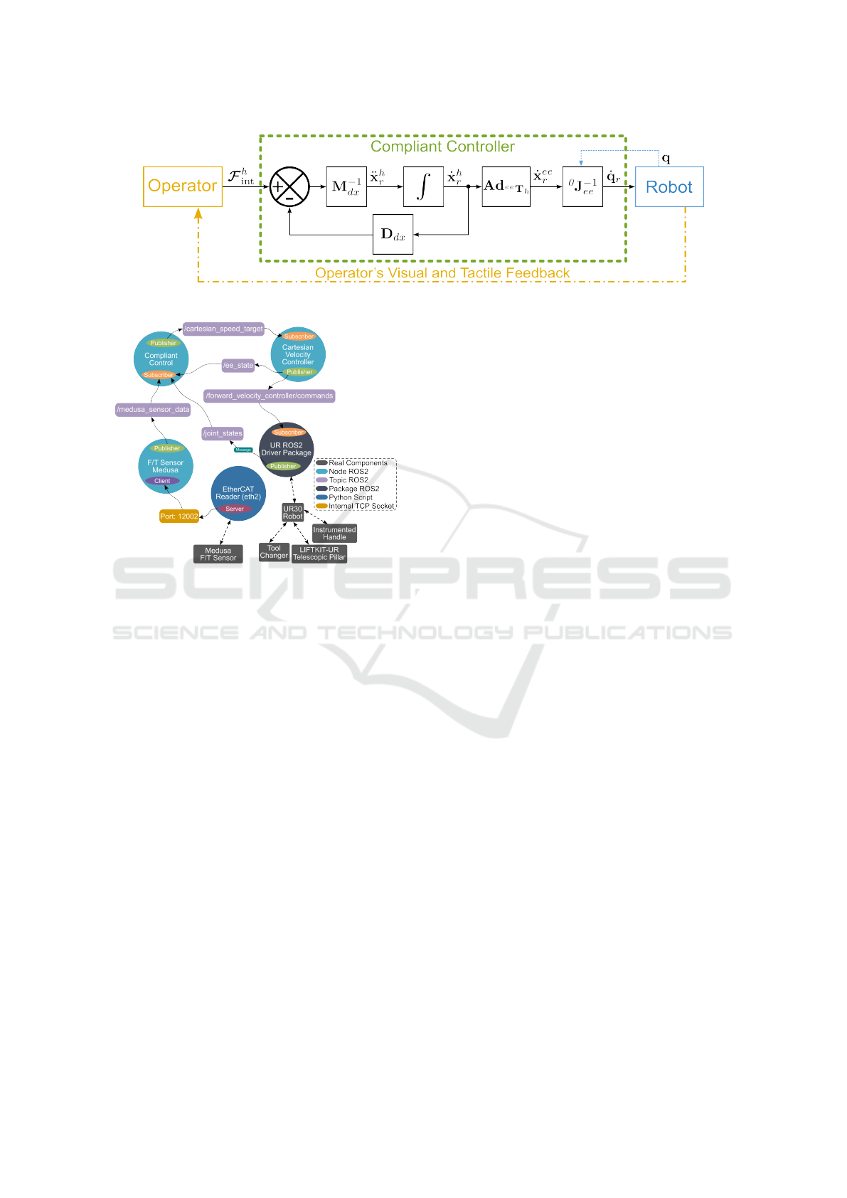
Figure 16: Block diagram of the implemented compliant control.
Figure 17: ROS2 control environment with one force/torque
sensor.
between the current loop period T
cur
and the nominal
period T
nom
:
Jitter = |T
cur
− T
nom
| (13)
Figures 18a and 18b show the measured loop jit-
ter for the compliant control node without and with
a real-time (RT) kernel, respectively. Using the stan-
dard kernel, significant jitter peaks exceeding 500 µs
were observed, whereas the RT kernel maintained jit-
ter consistently below 250 µs. This demonstrates a
clear improvement in temporal determinism when us-
ing real-time scheduling.
Figures 19 shows the end-to-end latency of the
control loop. Without real-time kernel, the mean la-
tency was 1881.4 µs with peaks above 2 ms, indicat-
ing delays within the 500 Hz loop. With real-time
kernel, the mean latency decreased to 541.2 µs, with
no peaks beyond 2 ms.
5 EXPERIMENTAL RESULTS
The previous sections described the integration of a
dual force/torque sensing architecture into the instru-
mented tool. However, the preliminary experiments
reported here were conducted using only the Medusa
sensor mounted on the tool.
The test scenario consisted of standard cutting
movements representative of a meat processing task.
Specifically, slow forward motions were executed
along the cutting direction, followed by rapid re-
turn movements towards another part of the meat
piece. These simplified yet representative conditions
were chosen to evaluate the dynamic behaviour of
the admittance-based compliant controller under hu-
man interaction in a meat-cutting use case. In this
configuration, only the displacement of the robot was
controlled in response to the operator’s applied force,
as amplification features were implemented but not
tested due to the use of a single sensor.
Figure 21a shows the estimated external force ap-
plied by the human operator, reconstructed from the
Medusa sensor data after bias and gravity compensa-
tion. In response, the compliant controller generates
a Cartesian velocity command as illustrated in Figure
21b.
To evaluate how well the robot tracks this refer-
ence motion, Figure 23a compares the commanded
Cartesian velocity with the measured velocity, derived
from joint encoders using the forward velocity kine-
matics:
˙
x
ee
robot
=
0
J
ee
˙
q
The correlation between both signals confirms the
robot’s internal controller accurately follows the ve-
locity commands.
Figure 23b presents the estimated force applied by
the robot at the end-effector. This is obtained from the
joint torques thanks to the relation:
F
F
F
ee
robot
=
0
J
−T
ee
Γ
Γ
Γ
Excluding contributions from the tool’s own dy-
namics and gravity. The plot highlights the robot’s
passive response to external forces applied by the hu-
man operator.
The transparency of the compliant control was
evaluated using the variable Y
diff
, defined as the ab-
solute difference between the measured and desired
COBOTA 2025 - Special Session on Bridging the Gap in COllaborative roBOtics: from Theory to real Applications
548
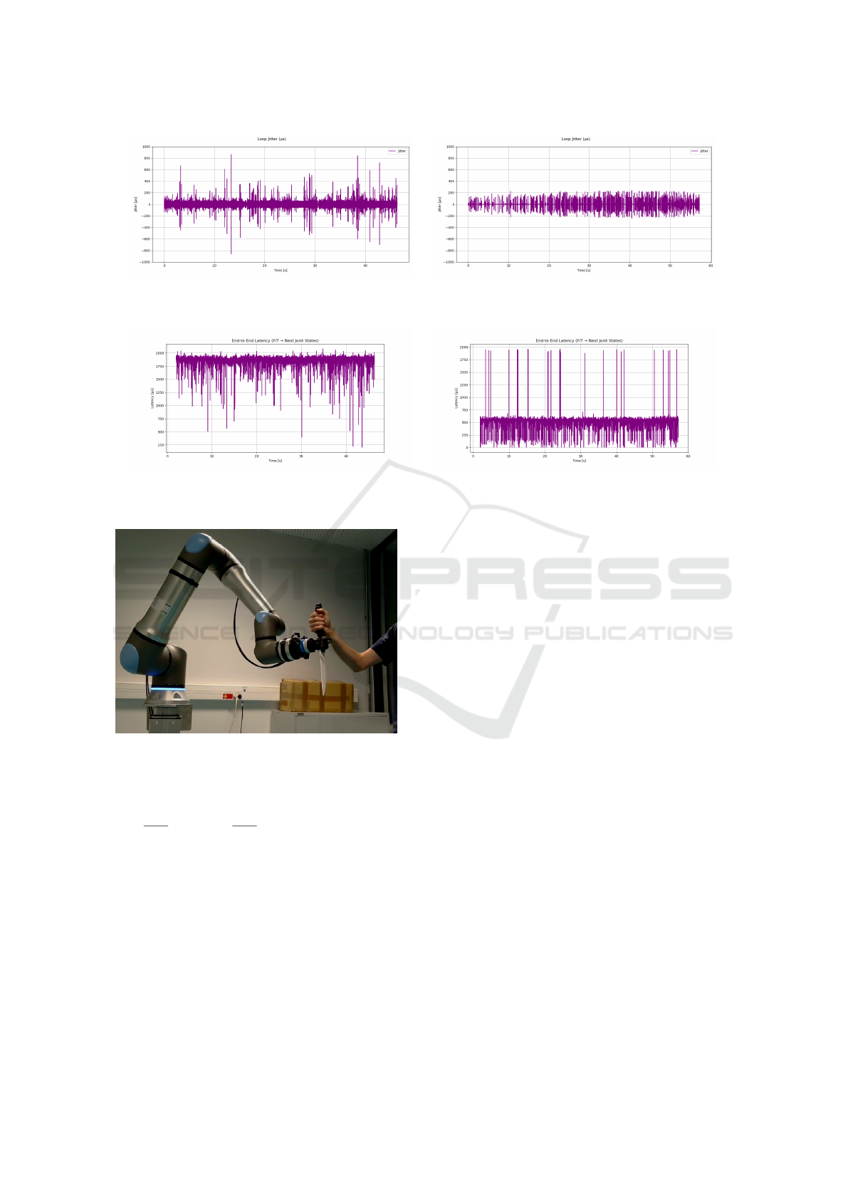
(a) Loop jitter without a real-time kernel. (b) Loop jitter with a real-time kernel.
Figure 18: Comparison of loop jitter for the compliant control node under standard and real-time kernels.
(a) End-to-end latency without a real-time kernel. (b) End-to-end latency with a real-time kernel.
Figure 19: End-to-end latency from sensor data acquisition to robot command execution.
Figure 20: Illustration of the human operator applying a
force on the handle, resulting in a tool motion.
admittance gains:
Y
d
=
˙x
h
r
F
F
F
h
int
, Y
mes
=
˙x
h
mes
F
F
F
h
int
, Y
diff
= |Y
mes
−Y
d
| (14)
where ˙x
h
r
is the commanded end-effector velocity in
the human reference frame, ˙x
h
mes
is the measured end-
effector velocity in the same frame, and F
F
F
h
int
is the
force applied by the human operator.
This first indicator of transparency for the com-
pliant motion demonstrates good performance dur-
ing standard movements: the robot successfully fol-
lows the human-induced motion, particularly during
phases of nearly constant velocity. However, when
rapid and large forces are applied (notably around
40s in the plots), the co-movements are insufficiently
smooth. The motion is strongly damped, which re-
sults in peaks in Y
diff
. This limitation is primarily due
to the damping matrix used in the current implemen-
tation, which reduces the operator’s intended dynam-
ics. A second contributing factor could be the robot
itself, as observed in Figure 23a, where a significant
discrepancy exists between the desired end-effector
velocity from the compliant controller and the mea-
sured value.
Future transparency indicators will be investi-
gated, focusing in particular on the frequency re-
sponse of the admittance rather than a simple absolute
deviation.
A promising direction for improvement is the im-
plementation of a variable damping matrix, as pro-
posed in (Sharkawy and Koustoumpardis, 2022), to
better reflect the operator’s intended accelerations.
This is particularly relevant for anatomical tasks such
as meat cutting, where the human performs motions
with frequent changes in direction and acceleration
amplitude.
These results are consistent with the existing lit-
erature and reinforce the practicality of implement-
ing Cartesian admittance control by generating joint
velocity commands. This approach benefits from
low-level integration, allowing the robot’s internal
controller to ensure stable and responsive behaviour
through the management of filtering, actuation limits
and dynamic consistency.
However, several limitations must be taken into
Preliminary Design and Control of an Operator-Assistance System Integrated into a Cobot, for Anatomical Meat-Cutting Process
549
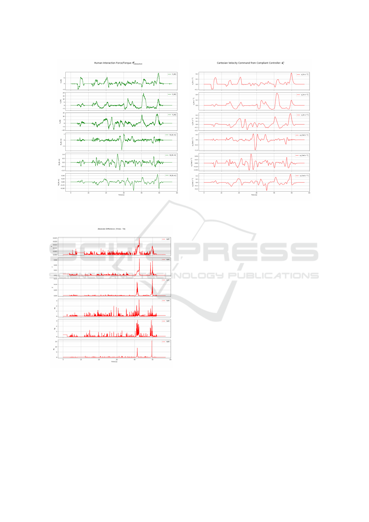
(a) Estimated human–robot interaction force. (b) Resulting Cartesian velocity.
Figure 21: Input and output of the compliant controller (expressed in the interaction frame h).
Figure 22: Absolute difference between measured and de-
sired admittance gains, Y
diff
, during compliant control.
account. Firstly, mapping Cartesian velocities to
joint velocities using the Jacobian can become ill-
conditioned near singularities, resulting in large joint
movements or noisy behaviour. Secondly, this strat-
egy depends on accurate dynamic modelling and sen-
sor calibration, as any error in force estimation di-
rectly affects motion quality. Additionally, when the
control loop does not operate in real time or lacks suf-
ficient frequency, latency can reduce responsiveness
and compromise safety.
6 CONCLUSION
This paper has presented the design and preliminary
results of the control of an operator-assistance system
integrated into a collaborative robot for the manipu-
lation of soft bodies, such as in meat-cutting tasks.
The system combines a carefully instrumented end-
effector with a Cartesian admittance controller to en-
able compliant and intuitive physical human-robot in-
teraction.
The mechanical design of the instrumented tool,
featuring dual force/torque sensors, has been val-
idated to effectively distinguish between operator-
applied forces and interaction forces with the soft ob-
ject. The communication infrastructure and control
strategy, based on velocity commands and admittance
control, have demonstrated promising preliminary re-
sults in delivering responsive and stable assistance.
Future work will focus on in-depth experimen-
tal validation in realistic industrial scenarios, on im-
proving the robot’s force control capabilities using a
method distinct from that proposed in (Hamad et al.,
2021), and on integrating adaptive control schemes to
manage the variability in the direction of force and
acceleration typically applied by the operator in tasks
such as meat cutting. Moreover, the integration of
advanced perception modalities and operator intent
COBOTA 2025 - Special Session on Bridging the Gap in COllaborative roBOtics: from Theory to real Applications
550
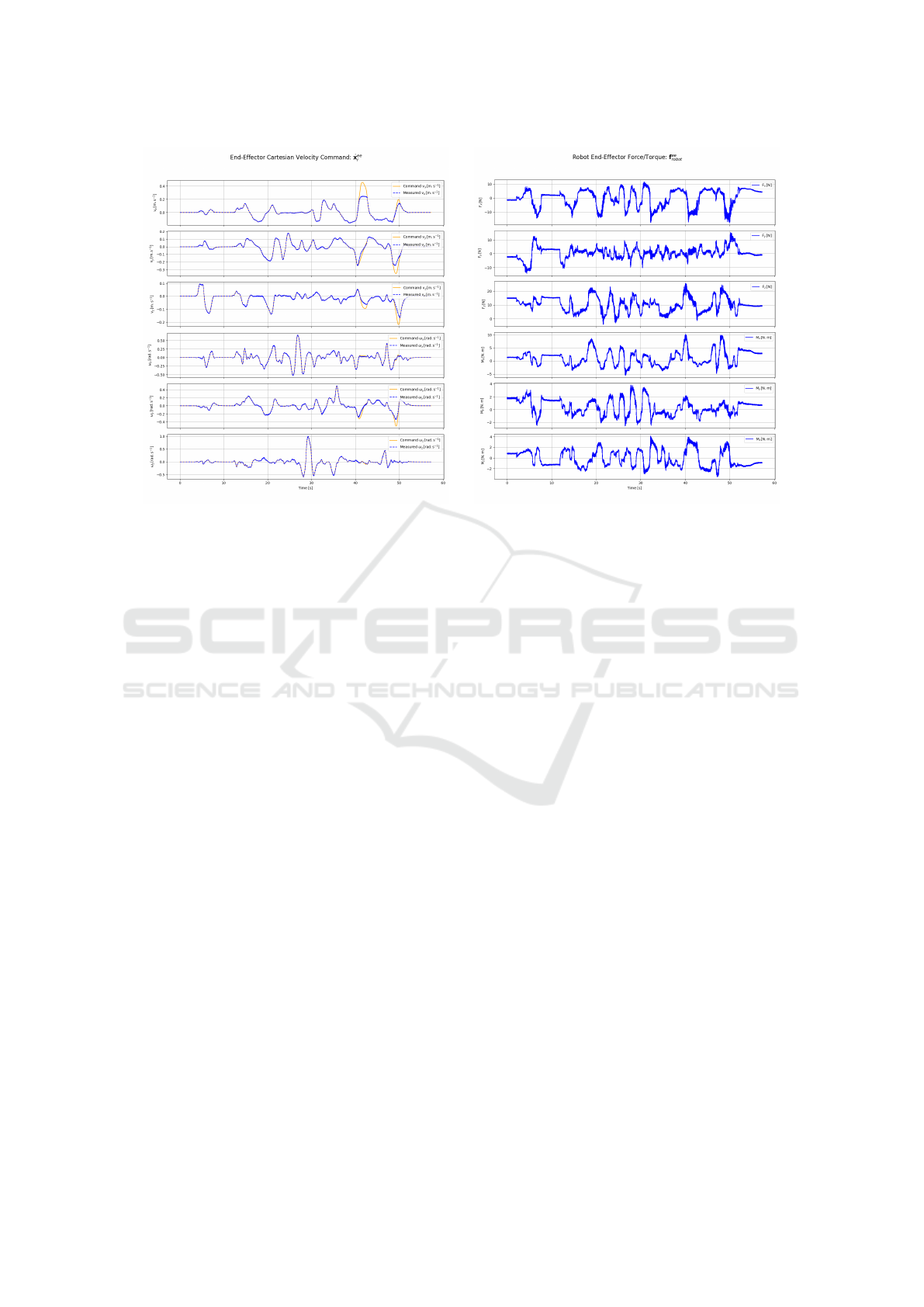
(a) Comparison between commanded and measured
end-effector velocity.
(b) Estimated force applied by the robot at the end-
effector.
Figure 23: Robot behaviour during compliant control.
recognition is expected to further enhance the sys-
tem’s robustness and usability.
Overall, this study lays the groundwork for the de-
velopment of collaborative robotic systems capable
of safely and efficiently manipulating deformable ob-
jects, while providing ergonomic assistance in tasks
involving soft body interaction. This opens new
opportunities for automation in complex, human-
centred industrial environments.
ACKNOWLEDGEMENTS
This work is funded by Interreg Sudoe, a European
Union funding program to support regional devel-
opment and cohesion in the regions of southwest-
ern Europe, as part of the ROBOTA Sudoe project
(S1/1.1/P0125): Robotics, Automation, and Digiti-
zation as Drivers of Competitiveness and Growth for
SMEs.
REFERENCES
Ajoudani, A., Zanchettin, A. M., Ivaldi, S., Albu-Sch
¨
affer,
A., Kosuge, K., and Khatib, O. (2017). Progress
and prospects of the human–robot collaboration. Au-
tonomous Robots, 42(5):957–975.
Farajtabar, M. and Charbonneau, M. (2024). The path
towards contact-based physical human–robot interac-
tion. Robotics and Autonomous Systems, 182:104829.
Hamad, Y. M., Aydin, Y., and Basdogan, C. (2021). Adap-
tive human force scaling via admittance control for
physical human-robot interaction. IEEE Transactions
on Haptics, 14(4):750–761.
Hogan, N. (1984). Impedance control: An approach to ma-
nipulation. In 1984 American Control Conference.
IEEE.
Keemink, A. Q., van der Kooij, H., and Stienen, A. H.
(2018). Admittance control for physical human–robot
interaction. The International Journal of Robotics Re-
search, 37(11):1421–1444.
Sharkawy, A.-N. and Koustoumpardis, P. N. (2022). Hu-
man–robot interaction: A review and analysis on vari-
able admittance control, safety, and perspectives. Ma-
chines, 10(7):591.
Preliminary Design and Control of an Operator-Assistance System Integrated into a Cobot, for Anatomical Meat-Cutting Process
551
