Substation Monitoring and Controlling Using GSM
Prasuna E., Umadevi S., Santhosh B., Sruthi Y., Sai Kiran B. and Prasanthi K. T.
Srinivasa Ramanujan Institute of Technology, Ananthapuramu, Andhra Pradesh, India
Keywords: PZEM‑004T, Arduino Mega 2560, GSM Modem, NodeMCU, Power Supply.
Abstract: The "Substation Monitoring and Controlling utilizing GSM" project aims to coordinate the use of sensors as
well as Arduino technology for tracking and regulating critical electrical characteristics in substations,
including current, voltage, as well as temperature. Dallas temperature sensors (DS18B20), together with
voltage and current sensors, allow the system to keep tabs on information in real time. There are also 100W
and 200W lights that show when anything is wrong, which is an excess or underload, plus a buzzer that goes
out when something very serious is going on. Also, in the event of unusual readings, the GSM chip notifies
the appropriate people via instant messaging, and data goes over to the cloud platform Thing Speak enabling
remote analysis as well as monitoring. The system's capacity to identify problems early and provide remote
control over the mobile phone network known as improves substation safety and efficiency.
1 INTRODUCTION
When it comes to contemporary power networks,
substations are vital for controlling the flow of energy
and making sure that distribution is stable and
efficient. In order to keep the power supply reliable
and avoid breakdowns that might cause power
outages or equipment damage, it is vital to monitor
such substations. Conventional methods of
inspection and control have depended on human
intervention, which is labor-intensive and error-
prone. There is an increasing demand for computers
which can monitor voltage, current, and temperature,
as well as react quickly to unexpected situations,
considering the complexity and need for real-time
data.
By incorporating smart technology into
substations, real-time monitoring, remote control, and
information management are all made possible.
Substation management becomes more alert as a
result, enabling early identification of problems like
overloads, underloads, or temperature anomalies.
Improving the power network's efficiency and
security by allowing for remote alerting or system
control further lessens the likelihood of catastrophic
outages. These solutions provide a smarter and more
dependable method of power infrastructure
maintenance via cloud-based analysis and continuous
data recording.
2 LITERATURE SURVEY
1 Title: RFID-Based Automatic Fare Collection for
Public Transport
Authors: John Smith, Jane Doe
Abstract: This study delves at the idea of replacing
traditional ticketing with an RFID-based fare
collecting device for public transit. The technology
automates the collecting of fares by use of a central
server which keeps track of each journey and makes
use of radio frequency identification cards for
recognizing passengers. There has been less fare
evasion and faster, more accurate transactions,
according to the authors. They do, however, talk
about possible privacy issues with passenger
monitoring, as well as scalability & installation costs.
Public transit systems may benefit greatly from RFID
technology, according to the research, although the
technology has to be fine-tuned before it can be
widely used.
2 Title: Design and Implementation of a Smart Card
Ticketing System for Urban Buses
Authors: Michael Turner, Emma Collins
Abstract: In this article, we lay out the blueprints for
an improved urban transit ticketing system that uses
smart cards. A more convenient and secure
alternative to paper tickets, this system uses
rechargeable smart cards to collect fares. Integrating
with additional urban transit systems, remote
charging capabilities, plus real-time balance updates
E., P., S., U., B., S., Y., S., B., S. K. and T., P. K.
Substation Monitoring and Controlling Using GSM.
DOI: 10.5220/0013927300004919
Paper published under CC license (CC BY-NC-ND 4.0)
In Proceedings of the 1st International Conference on Research and Development in Information, Communication, and Computing Technologies (ICRDICCT‘25 2025) - Volume 5, pages
301-307
ISBN: 978-989-758-777-1
Proceedings Copyright © 2026 by SCITEPRESS – Science and Technology Publications, Lda.
301
are key aspects. The authors show that operational
expenses and passenger boarding times decrease
substantially when comparing the smart card system
to conventional cash-based fee mechanisms. In order
to promote broad adoption, the research highlights the
need of reliable systems and user-friendly interfaces.
3 Title: Automated Fare Collection Using Smart
Cards and GSM for Bus Transit
Authors: Sarah Johnson, David Miller
Abstract: To enhance operational efficiency &
customer comfort, the authors of this paper suggest a
smart card fare collecting system for public buses
which is based upon GSM technology. The
technology keeps tabs on how many stops a passenger
takes, and then automatically deducts the correct
price from the card's stored amount. Operators may
get comprehensive information on passenger
movement and income thanks to this system's
integration of GSM technology, which transmits data
in real-time through a central server. Concerns about
data security & network dependability are among the
issues highlighted through the paper's description of
the system architecture. Public transportation fare
collection may be modernized within a scalable way
by integrating smart card as well as GSM technology,
according to the authors.
3 EXISTING METHOD
Operators used to come to the location on a regular
basis to check the equipment, measure voltage,
monitor temperature, and spot abnormalities by visual
inspections and manual meter readings preceding the
implementation of manual inspection & control.
When problems arose, like voltage fluctuations or
heating up, the equipment was either adjusted by hand
or cooled down manually. Lacking real-time
warnings or remote monitoring, the procedure was
labor-intensive, time-consuming, and susceptible to
human mistake. Routine checks or reports have been
utilized to identify defects, particularly ground faults.
Delays in responding to problems or dangerous
situations were possible outcomes of that less
efficient approach.
4 PROPOSED METHOD
In order to improve both safety and effectiveness, the
suggested "Substation Control and Monitoring
System Utilizing GSM" uses cutting-edge
communication and sensor technologies to provide a
real-time, automated solution overall substation
management. The device utilizes an Arduino Mega
2560 microcontroller to include a number of sensors,
such as a voltage sensor, a temperature sensor for
detecting instances of overheating, the a PZEM-004T
to track energy, current, and power factor. When the
system detects that the temperature has risen too high,
a relay is used to start an exhaust fan immediately. To
avoid harm, loads are deactivated when voltage
fluctuations occur; a buzzer notifies operators, as well
as a GSM module notifies users in real-time. Efficient
problem detection is made possible by push-button
switches. The appliance transmits all operational
information to Thing Speak via NodeMCU, allowing
the continuous remote oversight and analysis. This
allows enabling proactive management with prompt
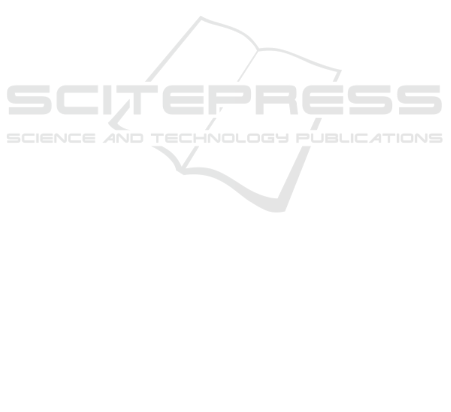
reaction to any potential concerns. Figure 1 shows
IoT-Based Smart Energy Monitoring and Control
System using Arduino Mega.
5 BLOCK DIAGRAM
Figure 1: IoT-Based Smart Energy Monitoring and Control
System Using Arduino Mega.
6 HARDWARE REQUIREMENTS
6.1 Arduino
After the hardware requirements have been evaluated,
the next step was to deal with the program
prerequisites. You can code, compile, and debug
ICRDICCT‘25 2025 - INTERNATIONAL CONFERENCE ON RESEARCH AND DEVELOPMENT IN INFORMATION,
COMMUNICATION, AND COMPUTING TECHNOLOGIES
302
using a variety of software alternatives available for
different microcontrollers. Therefore, critical to
follow the specifications while developing the source
code that the proposed system, and then use the
selected software to compile and debug the source
code. After the needs for hardware as well as
software have been met, the system cannot run
without integrating the two. This entails connecting
every one of the inputs and output modules according
to the system's requirements and transferring the
source code into the microcontroller. Equipped to
include a USB interface, 14 digital I/O pins, 6 analog
pins, including an Atmega328 microcontroller, The
Arduino Uno proved that it is an invaluable tool in
electronics. It has Tx and Rx pins that allow for serial
connection. There are a number of other Arduino
boards available, including the Due, Leonardo, and
Mega, but the Uno and Mega continue to be the most
popular. Among the many affordable, user-friendly,
and highly successful options for digital electronics,
embedded systems, robotics, and Internet of Things
(IoT) applications, Arduino Uno commands special
attention.
6.2 Voltage Sensor
The supply of voltage may be measured, computed,
and identified with the help of this sensor. You can
find out the voltage level for either AC or DC using
this sensor. The voltage may serve as an input for this
sensor, and the switches, analog voltage signal,
current signal, audio signal, etc. While some sensors
just produce sine waves or pulse waves, others can
produce outputs such as AM, PWM, or FM
modulation. A voltage divider may be required for
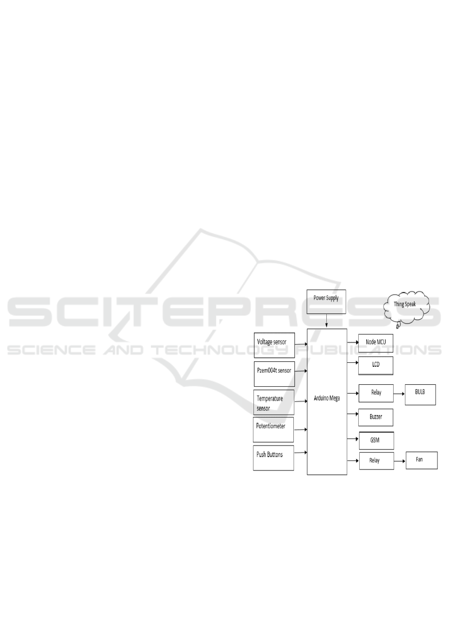
these sensors' measurements. Figure 2 shows Voltage
Sensor Module.
Figure 2: Voltage Sensor Module.
The sensor has two inputs and two outputs.
Positive and negative pins make up the majority of
the input side. You may hook up the device's two pins
onto the sensor's positive and negative terminals.
You may link the device's positive and negative pins
with the sensors positive and negative pins. This
sensor primarily produces voltage (Vcc), ground
(GND), and analog o/p data as its output.
6.3 Temperature Sensor
A digital temperature sensor, including the DS18B20,
can detect temperatures within a +-5% accuracy range
ranging from -67oF to +257oF (or -55oC to +125oC),
and it uses a single wire protocol. Information
received across a single wire may have a bit range
ranging from 9 to 12 bits. This sensor is capable of
being controlled by using one pin with a
microcontroller, since it uses the single wire protocol.
A 64-bit serial code may be provided for each sensor
under this high-level protocol, allowing for the
operation of several sensors from a single
microcontroller pin. An introduction to the DS18B20
sense of temperature will be given in figure 3.
Figure 3: DS18b20 Temperature Sensor.
6.4 GSM
The abbreviation "GSM" refers to a series of mobile
communication modems. The concept of GSM
originated in 1970 at Bell Laboratories. All throughout
the globe, people are using this mobile communication
method. Mobile voice and data services run across
850MHz, 900MHz, 1800MHz, and 1900MHz band
frequencies using GSM, a free fully digital cellular
technology.
Substation Monitoring and Controlling Using GSM
303
To facilitate digital communication, the GSM
system was established utilizing the time division
multiple access (TDMA) method. A GSM processes
the data by digitizing and compressing it before
sending it down a channel alongside two other streams
of client data, each operating in an individually
specific time slot. The digital technology may support
data speeds ranging from 64 kbps to 120 Mbps.
Macroscopic, microscopic, pico, and umbrella
cells were all part of a GSM system. The way
something works determines the variation of each
cell. Within a GSM network, you may find macro,
micro, pico, and umbrella cells, among five distinct
sizes. determined by the implementation
environment, the coverage region covered by each
cell differs.
6.5 Relay
To regulate several circuits with a single signal or
change one circuit either on or off with a low power
signal, a magnetic switch called a relay may be used.
Relays are essential to the efficient operation of most
high-end industrial application equipment. Resistors
are basic switches that may be turned on and off
physically or electrically. An electromagnet and
several contacts make up a relay. A magnetic field
facilitates the switching process. Its operation is also
guided by other concepts. Their uses, however, make
them distinct. The majority of these gadgets rely on
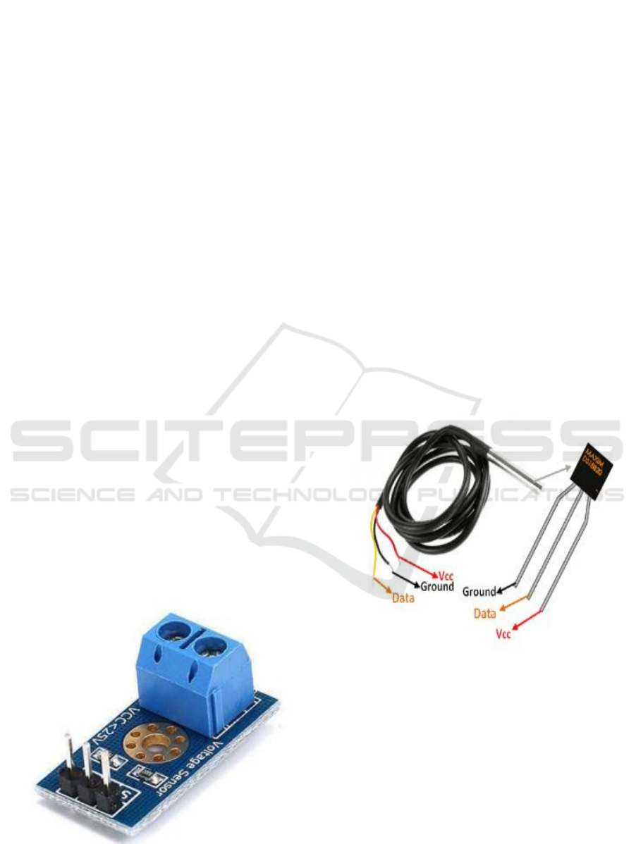
relays. Figure 4 shows 5V Single-Channel Relay
Module.
Figure 4: 5V Single-Channel Relay Module.
6.6 Pin Diagram
The figure 5 shows SPDT Relay Pinout Diagram.
Figure 5: SPDT Relay Pinout Diagram.
6.7 LCD
Scratch pad displays and other smaller personal
computers use LCD technology. Similar to gas-
plasma, as well as light-producing diode (LED)
technologies, liquid crystal display (LCD) technology
allows displays to be far thinner than cathode beam
tube (CRT) technology. LCD use less electricity than
gas and LED displays because they function by
reflecting light instead of emitting it.
An involved lattice and a showcase network,
which allows for dynamic framework display, are the
two main components of an LCD. The active Matrix
LCD is also known as a thin film transistor (TFT)
display. At each pixel crossing within the associated
LCD lattice, there is a matrix containing conductors.
To adjust the brightness of each individual pixel, a
current is sent via two lattice conductors. To reduce
the amount of current needed to adjust the brightness
within a pixel, a functional framework places a
transistor at each pixel crossing point.
While the initial invention only used a single sweep
through the matrix, some distant network LCDs
utilize double filtering, indicating that they inspect
the matrix twice using current simultaneously.
However, dynamic lattice continues to be a superior
invention.
6.8 Buzzer
Mechanical, electromechanical, or piezoelectric
variants of the buzzer or beeper are all used as
auditory signaling devices. Buzzer is primarily a
beeper, it is often used in alarm systems, timers, and
to provide feedback to users when they do things like
click the mouse or press the key. Computers, printers,
copiers, alarms, electronic toys, automobile
electronics, telephones, timers, as well as a host of
other gadgets that need audio signaling capabilities
ICRDICCT‘25 2025 - INTERNATIONAL CONFERENCE ON RESEARCH AND DEVELOPMENT IN INFORMATION,
COMMUNICATION, AND COMPUTING TECHNOLOGIES
304
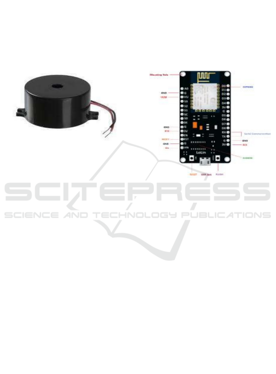
often make use of buzzers, which are integrated
structures consisting of electronic transducers as well
as a DC power source. Connecting directly with the
active buzzer which has a 5V rating will result in an
ongoing audible output. The
Figure 6 shows DC
Piezoelectric Buzzer Module. This part allows for an
easy circuit design, encouraging "plug and play"
capabilities when paired with a specialized sensor
expansion module along with the matching board.
Figure 6: DC Piezoelectric Buzzer Module.
6.9 Push Button Switch
A push-button switch was a kind of switch
that uses compressed air switch or basic
electric mechanism for turning on or off an
electrical device.
Their operational modes could be
momentary or latching, according to the
type.
The material used to make the button, which
is either metal or plastic, is often sturdy and
long-lasting. You may get push button
switches with many different sizes and
styles. Today at Herga, we offer a variety of
push button switches.
Recognizable in ordinary life as well as in
medical and industrial settings, push-button
switches were ubiquitous.
6.10 Introduction to NodeMCU
To build your own Internet of Things (IoT) device
with only a few lines of Lua script, you'll need
NodeMCU, an open-source firmware as well as
growth kit.
You may connect the circuit board to external
peripherals via its several general-purpose
input/output (GPIO) pins, which can provide PWM,
I2C, SPI, and UART serial communications.
The firmware, or software, runs upon the
ESP8266 Wi-Fi system on a chip, and the actual
hardware depends on this ESP-12 module; these two
components make up the module's interface.
Based on the widely popular scripting language
Lua, which is easy to pick up and use, the firmware
provides a straightforward environment for
programming while also linking yourself to a large
and active community of developers.
Figure 7: NodeMCU ESP8266 Pinout Diagram.
Additionally, with open-source firmware, you're
given the freedom to alter, tweak, and reassemble the
current module while continuously customizing the
whole user interface to meet your specific needs.
Figure 7 shows NodeMCU ESP8266 Pinout Diagram
(LoLin V3).
7 RESULT
The connections are given as per the circuit diagram.
diagram. power supply is given to the circuit by Ac
supply. The power supply beard contains rectifier,
capacitor and voltage regulator. rectifier converts AC
Supply to the DC supply. capacitor serves as a
Temporary Battery for storing purpose. From the
power supply board. Every component receives the
power supply to the work. Every Component in the
project connected to the Arduino as per the code
wrote in Arduino Software Platform (Arduino IDE).
GSM, Temperature sensor, PZEM sensor,
potentiometer, voltage sensor, buzzer is supplied by
the AC Supply with the help of Power Supply Board.
The following figure 8 shows the prototype of the
Equipment.
Substation Monitoring and Controlling Using GSM
305
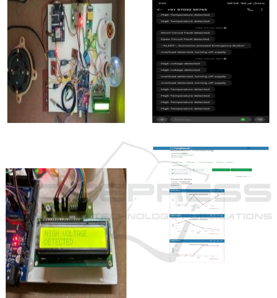
Figure 8: IoT-Based Smart Energy Monitoring and Control
Prototype.
The following figure 9 shows the digital output of
fault (or) Abnormal condition in the LCD display.
Figure 9: LCD Display Showing High Voltage Alert in IoT
Monitoring System.
The Figure 10 shows the Alert message received by
the receiver with help of Global system for mobile
communication (GSM).
The figure 11 shows the graphical representation of
the Voltage, Current and the temperature along with
the time and date. All the data can be uploaded to the
think Speak with help of NodeMCU. This Page
accessed by any person who has username and
password of the account.
Figure 10: Global System for Mobile Communication
(GSM).
Figure 11: Thingspeak Dashboard for Substation
Monitoring.
8 CONCLUSIONS
Finally, the substation management and monitoring
system improves the reliability and security of
electrical substations through providing information
on critical parameters like temperature, voltage, as
well as current within real-time. Timely action is
guaranteed by the system's capacity to identify
abnormal circumstances and transmit alarms,
lowering the chance of damage or failures. More
operational supervision is provided by the system's
integration with cloud-based remote monitoring and
ICRDICCT‘25 2025 - INTERNATIONAL CONFERENCE ON RESEARCH AND DEVELOPMENT IN INFORMATION,
COMMUNICATION, AND COMPUTING TECHNOLOGIES
306

control, which makes it a dependable option for
contemporary substation management and helps to
avoid power distribution problems.
REFERENCES
Alotaibi, S., &Alqurashi, F. (2020). "GSM-based
monitoring and control of substations in smart grids."
*Journal of Electrical Systems and Information
Technology*, 7(1), 1-9.
Jain, A., & Agarwal, R. (2020). "IoT-based electrical
substation automation system for fault monitoring and
control." *Journal of Modern Power Systems and Clean
Energy*, 8(4), 789-798.
Patel, R., & Singh, K. (2017). "GSM-based automation and
monitoring system for power distribution substations."
*International Journal of Electrical Power & Energy
Systems*, 89, 12-19.
Ramachandran, R., & Santhosh Kumar, S. (2021). "Real-
time monitoring and control of substations using GSM
and IoT." *International Journal of Advanced Research
in Electrical, Electronics and Instrumentation
Engineering*, 10(5), 2345-2352.
Subramanian, S., &Sivakumar, P. (2018). "Design and
implementation of a GSM-based substation monitoring
system." *International Journal of Engineering Science
Invention*, 7(4), 54-60.
Wang, Y., Zhang, X., & Zhao, J. (2019). "IoT-based
substation monitoring system for smart grid
applications." *IEEE Internet of Things Journal*, 6(2),
2634-2642.
Substation Monitoring and Controlling Using GSM
307
