
Advanced ST‑SMCS Control for Efficient Power Management in
Single Inductor Multi‑Port Converters for EVS
Pydikalva Padmavathi, Rolla Tarun Teja, Karna Golla Sai Saranya, Mandala Vaishnavi,
Mandla Shalom Simon and Devarakonda Vinay Kumar
Department of Electrical and Electronics Engineering, Srinivasa Ramanujan Institute of Technology, Anantapur, Andhra
Pradesh, India
Keywords: Super Twist Mode Controller (ST‑SMCS), Super Twist Algorithm, Stability, Reliability Battery State of
Charge.
Abstract: A Single Inductor Multi-Port Power Converter gives Super Twist Mode Controller for Electric Vehicles (EVs)
The controller uses the Super Twist Algorithm to improve power conversion efficiency, stability, and
reliability in changing conditions. While navigating through thousands of simulated input-output interactions,
the system traces their behavior, adapting its parameters to the variables, thereby handling the unpredictable
changes to the energization and load of the battery. The STSMCS includes the number of losing energy and
stability under real-time, which maximizes more stability and effectiveness as effectively as more
adaptability. This technology improves efficient power transfer, contributing to sustainable transportation by
strengthening EV power systems. Such a system makes EV (electric vehicle) system effective & efficient for
power conversion to meet any operational requirement and is a tangible progression in both power conversion
& the EV system.
1 INTRODUCTION
The increasing demand for electricity as well as the
depletion of fossil fuel reserves, especially those
powered by renewable sources such as those offered
by solar photovoltaic (PV) systems, has led to a rise
in the use of electric vehicles. Solar PV covers
sunlight to electricity, and it is optimized by
Maximum Power Point Tracking (MPPT).
However, its efficiency is negatively impacted by
issues such as variation in irradiance and
discontinuous availability. Hybrid energy storage
systems (HESS) considered several secondary
batteries along with the solar PV in order to stabilize
the output power for improving the overall
performance of electric vehicles under different
conditions. By integrating the two systems, it assures
energy consistency, extending the battery life, and
enhancing the handling on extreme terrains. This
enables HESS to optimize energy management and
reduce reliance on fossil fuels by allowing for a
continuous flow of power. It also overcomes some
of the limitations associated with the variability of
solar energy and enhances sustainability. In order to
integrate different energy sources efficiently, multi
input converters are necessary as employing separate
DC to DC converters increases the complexity and
cost of the system, similar to the one in Figure 5. In
hybrid energy storage systems, multi-port converters
are commonly adopted, which can be isolated or
non-isolated. Whereas isolated converters use
highfrequency transformers to achieve voltage
matching and electrical isolation, they introduce
additional losses and size. Non-isolated multiport
converters, like H-bridge systems, provide small,
high-performance, efficient solutions with
adjustable voltage levels and high efficiency energy
transfer to EVs.
Multi-port converter designs have recently been
proposed to balance the energy flow regulation
problem with the component count. For EV and
hybrid EV applications, an economical three-port
converter with integration of fuel cell, solar cell, and
batteries. Energy is managed with advanced
techniques to optimize power distribution and
continue to reduce component size, and zero-voltage
switching DCDC converters followed for greater
efficiency. On the other hand, high step-up non-
isolated converters can improve their performance
Padmavathi, P., Teja, R. T., Saranya, K. G. S., Vaishnavi, M., Simon, M. S. and Kumar, D. V.
Advanced ST-SMCS Control for Efficient Power Management in Single Inductor Multi-Port Converters for EVS.
DOI: 10.5220/0013921800004919
Paper published under CC license (CC BY-NC-ND 4.0)
In Proceedings of the 1st International Conference on Research and Development in Information, Communication, and Computing Technologies (ICRDICCT‘25 2025) - Volume 5, pages
11-18
ISBN: 978-989-758-777-1
Proceedings Copyright © 2026 by SCITEPRESS – Science and Technology Publications, Lda.
11

under varying conditions, and multi-output
converters can deliver stable voltage. The resulting
design is a multiport converter that satisfies the
problem with each port of the previous multiport
converters, making it a great candidate for the
modern EV industry.
2 LITERATURE SURVEY
Dhananjaya et al. (2022) introduced a new multi-
output DC-DC converter for EV applications,
dealing with cross-regulation problems in SIMO
topologies. They can control the voltage
independently, which improves the performance and
reliability of the EV power system. Its efficiency
under different conditions was validated by
MATLAB simulations and experimental results.
Athikkal et al. (2022) proposed a double input hybrid
step-up DC-DC converter used in industrial
applications with a main objective of improving the
power conversion performance of step-up DC-DC
converters by integrating dual power sources,
voltage gain optimization and reduced switching
power losses.
While the converter showed better performance
in terms of reliability and efficiency over a range of
loads, issues such as the complexity of controlling
the operation and stability under time-varying inputs
need more investigation. Alajmi et al. (2021)
proposed an efficient integration of PV systems with
a multi-port DC-DC converter. It provides better
energy management for renewable applications by
connecting both a grid and an alternative power
source to the same user/load. But issues such as
system complexity, thermal regulation, and stability
under changing solar conditions require more
optimization. Similarly, Khasim and Dhanamjayulu
(2021) summarize the selection parameters and
multi-input converter synthesis for electric vehicles
(EVs) by new demands for efficiency, power
density, and the integration of renewable energy.
They emphasized the importance of optimized
switching strategies and control mechanisms to
enhance system performance. Challenges like
component cost, thermal management, and system
complexity need more research. Faridpak et al.
(2020) developed a super-lift Luo-converter in series
with pop-up buck converters for EV applications to
improve the voltage gain and efficiency of the
converter and achieve a small construction. Their
work demonstrated a stellar power conversion
efficiency and voltage stability compared to
conventional converters. Nevertheless, issues such as
circuit complexity, thermal control and practical
deployment.
3 METHODOLOGY
3.1 Modelling of PV Array
When it comes to Electric Vehicles (EVs),
understanding how a Single Inductor Multiple Output
(SIMO) Converter works is key to managing power
efficiently. Full circuit simulation of the SIMPC
integrated with battery and multiple sources, and
equivalent circuit analysis of I-V; P-V characteristic
as well as load profile and dynamic operating
conditions.
The SIMPC efficiently manages power flow from
different sources, including the battery, regenerative
braking, and external power inputs, ensuring optimal
energy utilization. The analogous circuit of a solar
cell is shown in figure 1, incorporating the resistance
when connected in a series configuration (R
s
) and
resistance by connected in parallel (R
p
) alongside a
diode to model its electrical behaviour.
Figure 1: Solar cell analogous circuit representation.
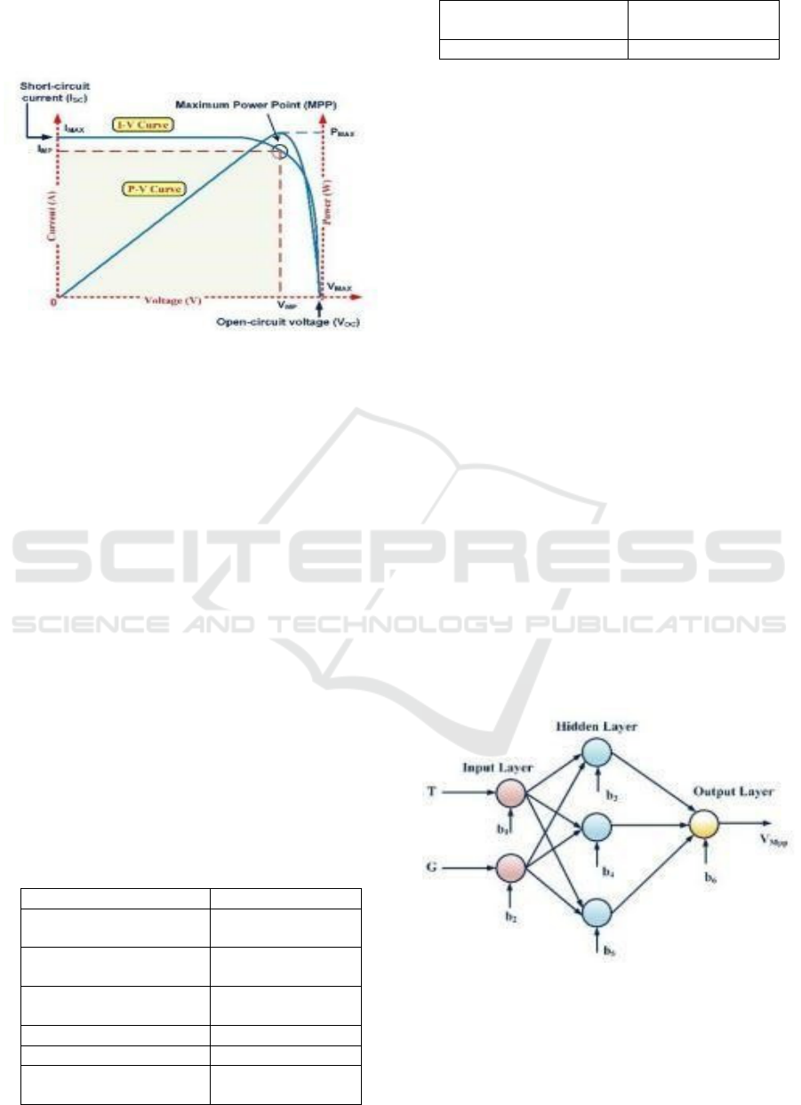
The graphical representation highlights the inherent
instability of a solar PV system’s operating point,
which constantly shifts between zero as well as the
voltage measured under open-circuit conditions. The
specific point where the solar module produces
maximum power, based on its design parameters
under varying temperatures and irradiance levels, is
called the maximum power point (MPP).
A PV array's output voltage and current depend
on factors such as temperature, irradiance, and the
series parallel configuration of its strings. Selecting
an appropriate solar panel requires careful
evaluation. This method considers a Soltech 1STH-
215-P panel with two parallel strings, each
containing two series connected modules. MATLAB
data is used for panel selection. Table 1 presents the
characteristics and measurements of a single series
ICRDICCT‘25 2025 - INTERNATIONAL CONFERENCE ON RESEARCH AND DEVELOPMENT IN INFORMATION,
COMMUNICATION, AND COMPUTING TECHNOLOGIES
12
module and a parallel-connected string at 1000 W/m²
irradiance and 77°F. Figure 2 shows the Solar Cell I-
V Characteristics.
Figure 2: Solar Cell I-V characteristics.
3.2 MPPT Controller
Environmental factors, such as temperature and
solar irradiance, are key in determining the power
output capability of a solar module. Real time MPPT
Implementation with efficient energy transformation
in EV power systems since solar energy generation
will depend on weather. There are three major
categories of MPPT techniques, which include AI
based methods, direct search algorithms, and indirect
estimations. Continuously tracking the mpp, direct
MPPT techniques (or real-time search-based
methods) adjust the operating point of the PV array.
These include Incremental Conductance (INC),
Perturb and Observe (P&O), and Hill Climbing
(HC) based approaches. Where P&O algorithm
observes the MPP by analyzing the variations of the
output voltage and the HC techniques maintain the
duty cycle of the converter. These methods, while
simple and widely used, are more efficient for low-
power systems because of their steady-state
behavior.
Table 1: Specifications of a 215W Solar Panel.
Parameter Value
Open circuit voltage
(Voc)
36.3V
The voltage at maximum
power point (VMPP)
34V
The voltage at maximum
power point (VMPP)
35V
Short circuit current (Isc) 7.84A
Maximum power 213.15W
Diode saturation current
(I0)
2.9259 × 10^-10 A
Current at maximum
power point (IMPP)
7.35A
Diode ideality factor 0.98117
The most widely used schemes is the incremental
conductance method for reducing steady state
oscillations at MPP. In this regard indirect methods
and artificial neural networks have been around to
improve the efficiency and responsiveness of the
MPPT. By taking into account the non-linear
dynamics of PV arrays, AI-based approaches are
quick but can be expensive computationally.
Indirect methods instead estimate the MPP based on
the output characteristics of the system.
This work make use of ANN for MPP tracking in
a Photovoltaic Solar Energy System. As shown in
Figure 3 is a three-layer ANN structure for MPP
identification. The ANN parameters cover
temperature and irradiance as input features, and its
output is the value of its MPP voltage (Vmpp). To
ensure accurate training, a dataset comprising input
variables and corresponding output values is
collected, allowing for the optimization of neuron
weights at various layers. For data acquisition and
programming, MATLAB is utilized to process solar
PV system data. Among the different training
techniques available for ANNs, thi study implements
the backpropagation algorithm to minimize errors
and enhance tracking accuracy. After training the
ANN, the neuron weight’s must be assigned. For
instance, the ANN generates V
mpp
as an output based
on the input parameters T and G. Using the modeled
PV system’s V-I characteristics, the corresponding
MPPT current (I
mpp
) can then be calculated.
Figure 3: Neural network-based framework for maximum
power point tracking (MPPT).
As a result, the maximum power
(P
max
)idetermined by multiplying V
mpp
and I
mpp
. The
PV system and MPPT tracker, illustrated in Figure 4,
include an ANN-based control unit and a converter.
Advanced ST-SMCS Control for Efficient Power Management in Single Inductor Multi-Port Converters for EVS
13
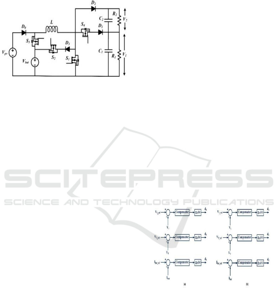
3.3 Proposed DC-DC Converter
Figure 4: Novel dual-input dual-output multi-port converter
architecture.
Figure 4 illustrates the two-input, two-output
configuration of the converter that is proposed. The
energy distribution from dual sources at the input is
analyzed using load resistances R
1
and R
2
. To
enhance the switching efficiency of the converter, the
power flow between sources and load resistances is
controlled by modulating voltages at the input.
Additionally, voltages at the output could be
modified based on voltages at the input of the
multilayer inverter, ensuring efficient power
management. Because of its sturdy construction, this
converter is ideal for combining a battery with a solar
photovoltaic system. Using the designated circuit
components, illustrates how power moves from the
energy sources to the load. The load resistances (R1
and R2) can be represented in terms of the motor's
equivalent resistance and the input voltages of the
multilayer inverter. Moreover, the proposed
controller may also be interfaced with a variety of
multilevel inverters which truly makes it a versatile
solution for energy management in electric car
applications.
The asymmetrical voltage source requirements of
multilevel inverters can all be met by the proposed
controller. Four switches are considered to control
energy transmission from voltages across input to
those across output in the stacked inverter which
increase voltage adaptability and control through the
use of multilayer inverter.
In an EV power system, a new method, especially
for the Super Twisting Sliding Mode Control System
(ST-SMCS) is introduced to control the flow of
power between battery (Vbat) and solar PV (Vpv).
Vbat can't power Vpv but Vpv powers Vbat so
energy is used more wisely. In EV applications,
batteries are usually charged via solar PV or external
sources since solar PV is not rechargeable by the
battery. Battery charge-based controller the
controller operates in different modes depending
upon the charge Available in battery and the load
Demand. When the demand is very high, only the
energy sources will provide power, while S1, S3, and
S4 are connected, and S2 is off. Also when demand
is low Vpv charges Vbat and load is served by Vpv
as S1, S2 and S4 are ON and S3 is OFF. In order to
operate both stable and efficient, the system will
balance the power accordingly and minimizes ripple
current, allowing the entire system to work as best
suited to the EV.
Historically, controllers are mainly evaluated for
performance in steady-state and dynamic scenarios
to ensure the best operation in continuous conduction
mode (CCM). A reduction of the power consumption
in fuction of the electricity demand of the load is
done by the converter working in discontinuous
conduction mode (DCM) at low energy demand
when charging a battery needs very low current to
avoid energy loss. Part IV provides a detailed
examination of the various input sources by
analyzing all input sources separately, allowing for
single-input operation, to directly manage the flows
of power. This includes Modes of operation where
the converter operates primarily in battery charging
and discharging modes for horizontal, well2, and
well4-based EVs.
Figure 5 shows the Adaptive
Control Mechanism of the Proposed Converter in (a)
Discharge Phase and (b) Charge Phase.
Figure 5: Adaptive control mechanism of the proposed
converter in (a) Discharge Phase and (b) Charge Phase.
The Super Twist Sliding Mode Control (ST-SMC)
method is one of robust control methods that
establishes stability by driving the system trajectory
to a specified sliding surface and then maintain it in
this sliding mode in the face of uncertainties and
disturbances.
ICRDICCT‘25 2025 - INTERNATIONAL CONFERENCE ON RESEARCH AND DEVELOPMENT IN INFORMATION,
COMMUNICATION, AND COMPUTING TECHNOLOGIES
14
Defining the Sliding Surface: In the first stage of
ST-SMC algorithm, we define the sliding surface
based on the desired dynamics of the system and
also the tracking errors. The sliding surface for a
single-input system is generally given
by:s(x)=x˙+λx (1)
where: x is the state variable. Λ is a positive constant
that determines the system’s behavior and
convergence rate.
3.4 ST-SMC Consists of Two Control
Steps
Step 1: Twist Control:
This step applies a discontinuous control law to drive
the system trajectory toward the sliding surface. It is
given by:
u
1
=−k
1
sign(s(x)) (2)
where k
1
>0 is a control gain. The sign function
ensures rapid correction of deviations, pulling the
system toward the sliding surface.
Step 2: Super Twist Control:
To further refine the control and reduce errors, a
second component is added that incorporates the
derivative of the sliding variable:
u2=−k2s˙(x) (3)
where k
2
>0 is another positive control gain. This term
smooths out control actions, reducing system
oscillations and improving precision.
Combining the Control Laws:
The total control input is the sum of the two
components:
u=u1+u2=−k1sign(s(x))−k2s˙(x) (4)
This composite law guarantees that the system
reaches the sliding surface and stays on it along the
desired trajectory and is not influenced by outside
disturbances.
4 STABILITY AND ROBUSTNESS
It provides for guaranteed stability and stability
robustness, even for highly nonlinear or uncertain
systems, reproducing the STSMC algorithm with
guaranteed convergence under linear and nonlinear
constraints, ensuring that the trajectory can be
guaranteed to converge to the sliding surface and
then sufficiently stay on it. This methodology is
commonly adopted in control applications where
accuracy and resilience are essential.
5 SIMULATION RESULTS
5.1 Discharging Mode
A uni directional DC to DC converter with battery to
assist the virtual battery energy storage device. It
governs the energy generated by the PV panel to
satisfy the load and charge the battery when
necessary. Critical components that help control the
power flow and maintain voltage stability, include
Diodes (D0–D3), capacitors (C1, C2), and switching
devices (S1–S4). Current measurements are used to
monitor the behaviour of a battery charge and
discharge while voltage measurements (V1, V2, VT)
indicates the levels of the output. This facilitates
efficient power transferring, allowing this system to
provide energy from the battery when the PV output
is low.
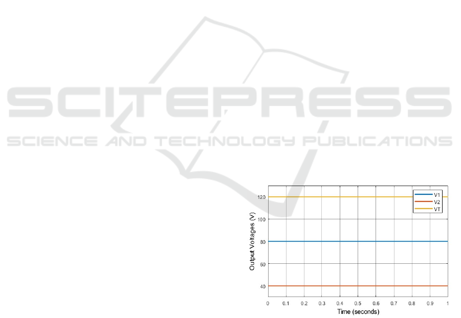
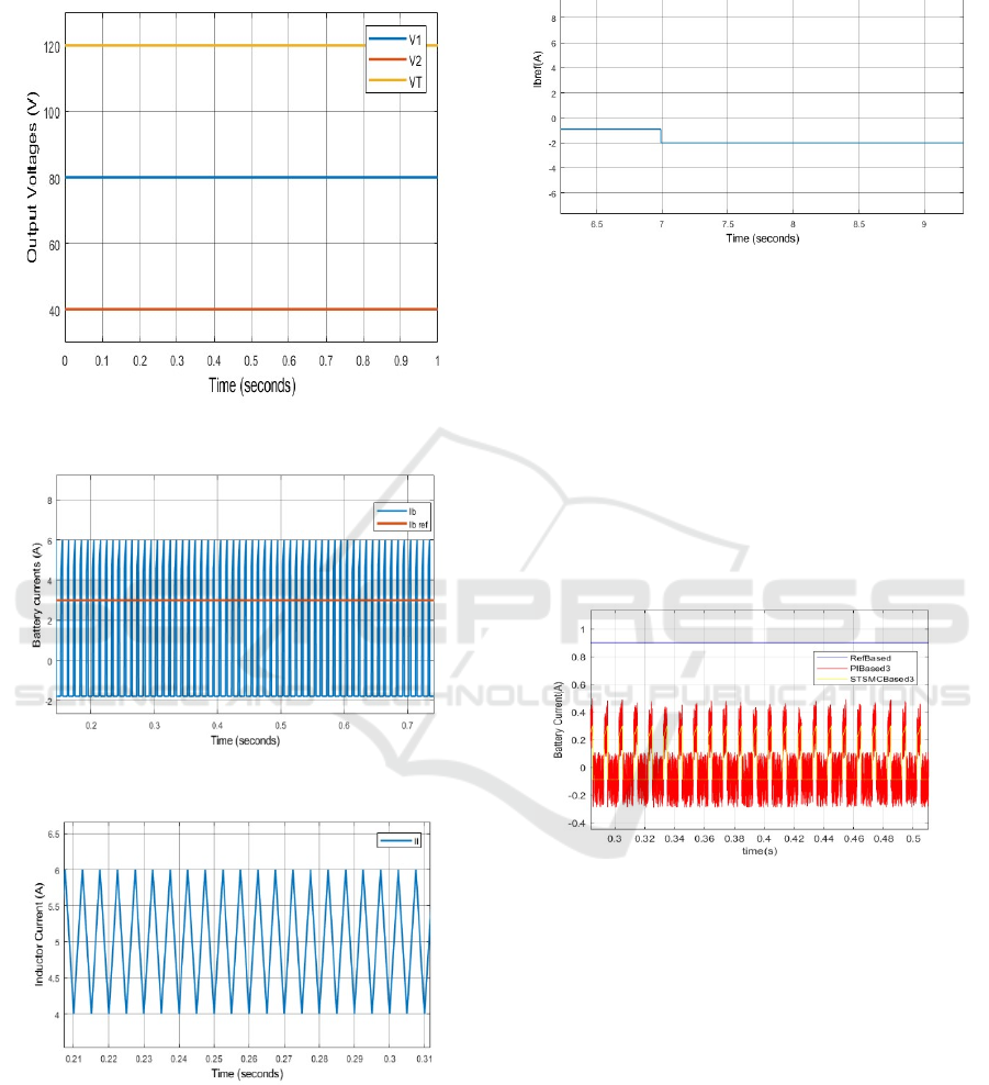
The voltages at the output nodes (V1, V2, and
VT) during battery discharge mode (through the
inductor) are plotted for one second in Fig 8. The
voltages with V1 40V, V2 80V, and VT ~120V does
not change indicating good DC to DC converter
regulation. The constant voltage levels imply that the
battery is successfully and consistently powering the
load. This attests to the system's capacity to sustain a
consistent power output throughout the discharging
stage.
Figure 6: Voltage response during battery discharge.
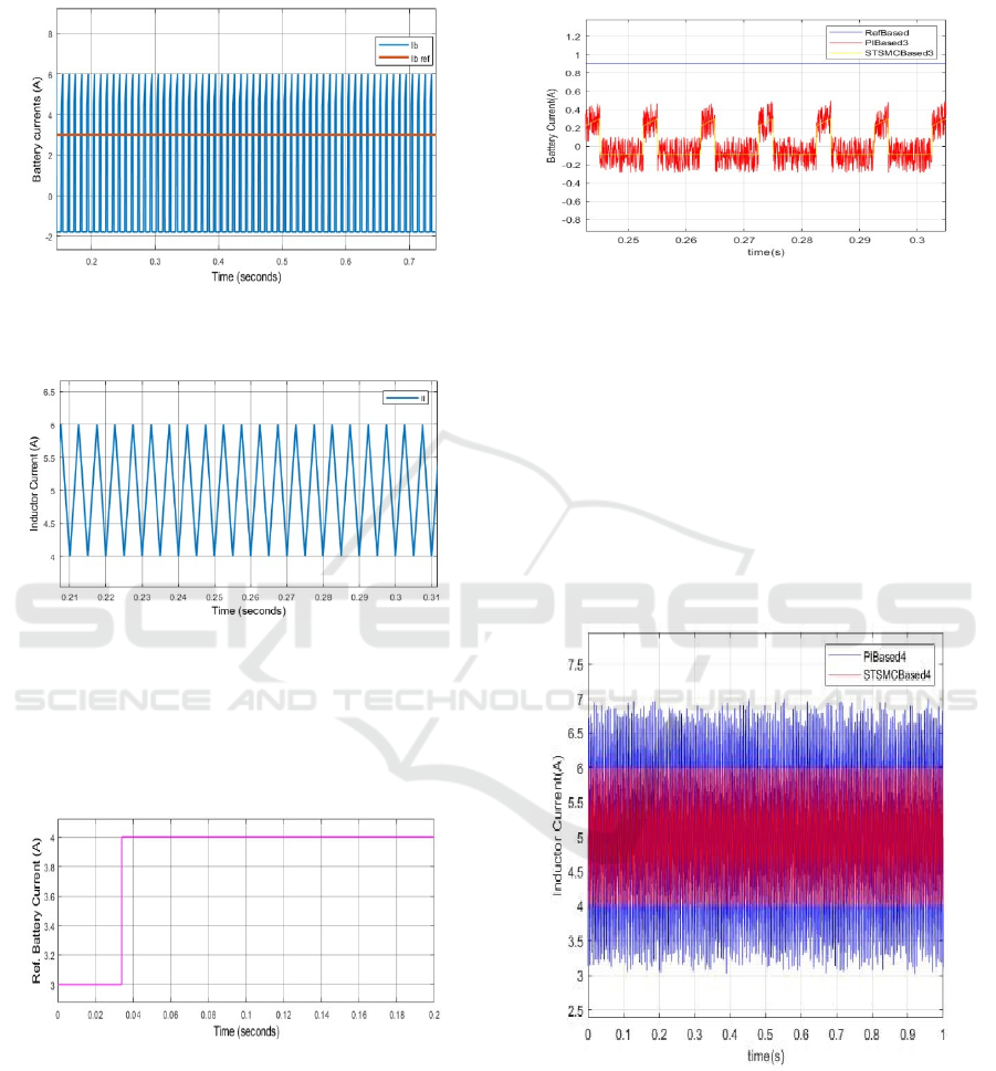
The Target Current Value remains steady at
approximately 3.5A, ensuring controlled power
delivery to the load, while the actual battery current
(I
b
) fluctuates slightly due to the DC-DC converter's
switching action. Figures 6, 7 and 8 depict the
Advanced ST-SMCS Control for Efficient Power Management in Single Inductor Multi-Port Converters for EVS
15
Battery Current, Reference Battery Current, and I
C
in
Discharging Mode, respectively.
Figure 7: Comparison of battery current and control
reference current during discharge mode.
Figure 8: Inductor current in discharging mode.
The photo voltalic panel generates electricity, the
battery stores extra energy and supplies it when
needed, and the converter regulates voltage and
current for a stable output. Figure 9 illustrates the
variation in battery reference current.
Figure 9: Change in battery reference current.
The graph represents battery current (A) over
time (s) for three different control methods:
RefBased4 (blue), PIBased3 (red), and
STSMCBased3 (yellow). The STSMC-based control
demonstrates higher fluctuations while keeping the
current within a specific range, whereas the PI-based
approach shows comparatively lower variations. The
reference current remains steady, acting as a standard
for evaluating performance. Figure 10 illustrates the
Comparison of Battery Current Using Different
Control Strategies.
Figure 10: Comparison of Battery Current Using Different
Control Strategies.
The graph represents inductor current (A) over time
(s) for two control methods: PIBased5 (blue) and
STSMCBased5 (red). The STSMC-based approach
demonstrates smoother performance with reduced
oscillations, while the PI-based method exhibits
higher fluctuations around the set current value. This
comparison highlights the effectiveness of STSMC
in maintaining stable inductor current Figure 11
illustrates the Inductor Current Comparison for PI-
Based and STSMC-Based Control.
Figure 11: Inductor current comparison for PI-Based and
STSMC-Based control.
5.2 Charging Mode
To maintain stable power delivery and enable real-
time voltage and current monitoring, the photo
voltalic panel generates electricity, the battery stores
surplus power for future use, and the converter
ICRDICCT‘25 2025 - INTERNATIONAL CONFERENCE ON RESEARCH AND DEVELOPMENT IN INFORMATION,
COMMUNICATION, AND COMPUTING TECHNOLOGIES
16
dynamically regulates voltage and current. The
resultant voltage, battery power, and inductor current
are depicted in Figure 12, 13, and 14, respectively
Figure 12: Output voltages in charging mode.
Figure 13: Battery current and reference battery current.
Figure 14: Inductor current in charging mode.
The converter regulates energy flow, with the PV
panel supplying power while the battery charges or
discharges based on changes in the reference current.
This mechanism ensures stable voltage and current
delivery to the load while enabling real-time system
monitoring. The graph illustrating the different in
battery current is presented in Figure 15.
Figure 15: Change in reference battery current.
The graph illustrates battery current (A) over time
(s) for three control strategies: RefBased (blue),
PIBased3 (red), and STSMCBased3 (yellow). The
reference current remains steady, while the PI-based
and STSMC-based methods show oscillations, with
STSMC exhibiting slightly higher fluctuations. This
shows the performance comparison and differences
between traditional PI and advanced STSMC
controller techniques. Schematic representation of
the Battery Current Response for Various Control
Strategies is shown in Figure 16.
Figure 16: Battery current response for different control
strategies.
The induturing current (A) over time (s) both for
PIBased4 (blue) and STSMCBased4 (red) control
methods is depicted. The response using STSMC
method has a smoother curve and less fluctuating
performance compared to that of PI achieved
approach. Extending this analysis to the inductors
spectrum regarding their oscillatory dynamics
would provide a more sophisticated insight into how
the STSMC technique outperformed previous
results. Inductor Current Response Using PI-Based
and STSMC-Based Control as Recorded in Figure
17.
Advanced ST-SMCS Control for Efficient Power Management in Single Inductor Multi-Port Converters for EVS
17
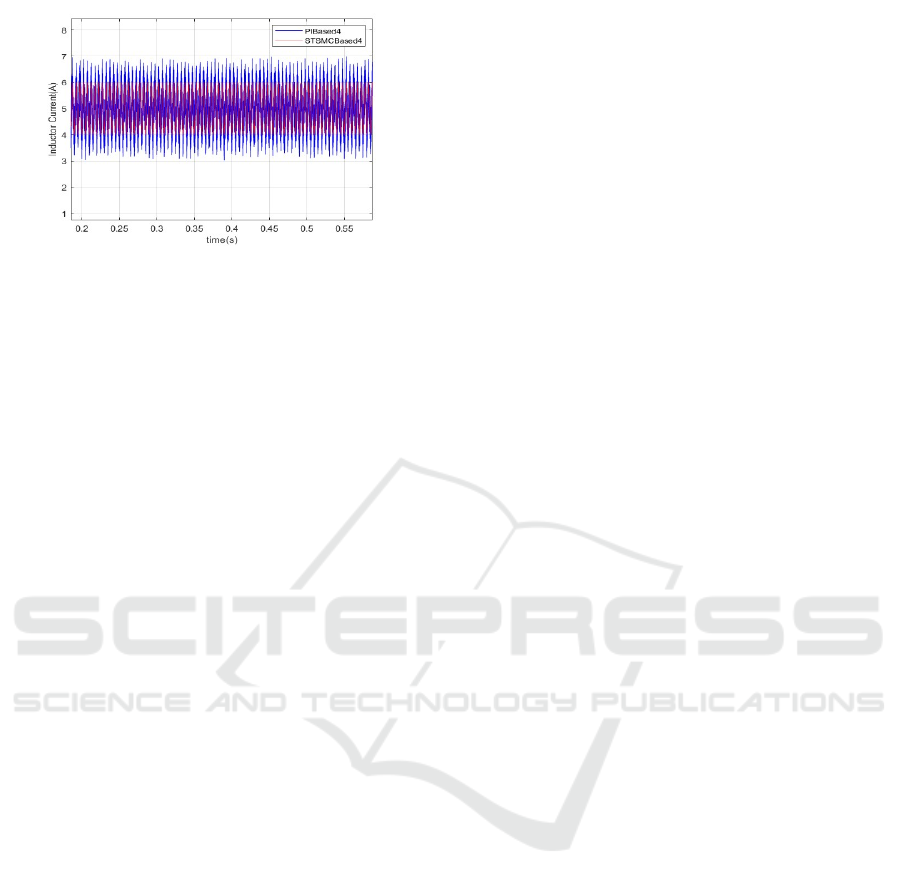
Figure 17: Inductor current response using PI-Based and
STSMC-Based control.
6 CONCLUSIONS
To summarize, the design performance has a
significant improvement by applying the Super-
Twisting Sliding Mode Control (STSMC) for Single
Inductor Multi-Port Power Controller in EV
applications. By replacing the classical PI-based
controller by the proposed one based on STSMC,
the method succeeds in dampening chattering as well
as restoring the voltage and current distortions. This
leads to a smoother and more stable operation.
Moreover, in comparison with STSMC, the
integration of a compensator achieves better
disturbance rejection response and also provides a
quick dynamic response against changes in load
conditions.
The findings of the Simulated and Empirical
Evaluations validate the proposed advanced control
strategy, showcasing a decrease in steady-state error
and enhanced efficiency in the aggregation of
multiple energy sources, such as battery and solar
panel networks. With its data-driven power
distribution and management, this approach is
required for electric vehicles since the need for
energy is dynamic depending on driving conditions.
The proposed STSMC-based system is assessed to be
suitable for use in EV applications, highlighting its
advantages as a cost efficient and energy-effective
solution for numerous energy splits, encourages
performance improvement and diminishes
distortions.
REFERENCES
A. Ajami, H. Ardi, and A. Farakhor, ‘‘A novel high step-up
DC/DC converter based on integrating coupled
inductor and switchedcapacitor techniques for
renewable energy applications,’’ IEEE Trans. Power
Electron., vol. 30, no. 8, pp. 4255–4263, Aug. 2015,
doi: 10.1109/TPEL.2014.2360495.
doi: 10.1109/TVT.2011.2122272.
J. Macaulay and Z. Zhou, ‘‘A fuzzy logical-based variable
step size P&O MPPT algorithm for photovoltaic
system,’’ Energies, vol. 11, no. 6, p. 1340, May 2018,
doi: 10.3390/en11061340.
K. Suresh, C. Bharatiraja, N. Chellammal, M. Tariq, R. K.
Chakrabortty, M. J. Ryan, and B. Alamri, ‘‘A
multifunctional non-isolated dual input-dual output
converter for electric vehicle applications,’’ IEEE
Access, vol. 9, pp. 64445–64460, 2021.
L. Wang, E. G. Collins, and H. Li, ‘‘Optimal design and
realtime control for energy management in electric
vehicles,’’ IEEE Trans. Veh. Technol., vol. 60, no. 4,
pp. 1419–1429, May 2011,
M. Zandi, A. Payman, J. P. Martin, S. Pierfederici, B.
Davat, and F. Meibody-Tabar, ‘‘Energy management of
a fuel cell/supercapacitor/ battery power source for
electric vehicular applications,’’ IEEE Trans. Veh.
Technol., vol. 60, no. 2, pp. 433–443, Nov. 2011, doi:
10.1109/TVT.2010.2091433.
M. R. Banaei, H. Ardi, R. Alizadeh, and A. Farakhor,
‘‘Non-isolated multiinput-single-output DC/DC
converter for photovoltaic power generation systems,’’
IET Power Electron., vol. 7, no. 11, pp. 2806– 2816,
Nov. 2014, doi: 10.1049/iet-pel.2013.0977.
M. Dhananjaya, D. Ponuru, T. S. Babu, B. Aljafari, and H.
H. Alhelou, ‘‘A new multi-output DC–DC converter for
electric vehicle application,’’ IEEE Access, vol. 10, pp.
19072–19082, 2022.
P.-J. Liu, Y.-K. Lo, H.-J. Chiu, and Y.-J. Emery Chen,
‘‘Dual-current pump module for transient improvement
of step-down DC–DC converters,’’ IEEE Trans. Power
Electron., vol. 24, no. 4, pp. 985– 990, Apr. 2009, doi:
10.1109/TPEL.2008.2010322.
S. R. Khasim and C. Dhanamjayulu, ‘‘Selection parameters
and synthesis of multi-input converters for electric
vehicles: An overview,’’ Renew. Sustain. Energy Rev.,
vol. 141, May 2021, Art. no. 110804, doi:
10.1016/j.rser.2021.110804.
S. R. Khasim and C. Dhanamjayulu, ‘‘Design and
implementation of asymmetrical multilevel inverter
with reduced components and low voltage stress,’’
IEEE Access, vol. 10, pp. 3495–3511, 2022, doi:
10.1109/ACCESS.2022.3140354.
ICRDICCT‘25 2025 - INTERNATIONAL CONFERENCE ON RESEARCH AND DEVELOPMENT IN INFORMATION,
COMMUNICATION, AND COMPUTING TECHNOLOGIES
18
