
Dynamic Wireless Charging for E‑Vehicles
Krishnaveni R., Abilash S., Abinesh A. J. and Balaji M.
Department of Electronics and Communication Engineering, KIT‑Kalaignar karunanidhi Institute of Technology,
Coimbatore, Tamil Nadu, India
Keywords: Dynamic Wireless Charging, Inductive Power Transfer, Electric Vehicles (EVs), Battery Management
System (BMS), Power Conversion System, Sustainable Mobility, High‑Frequency Magnetic Field.
Abstract: Dynamic wireless charging for electric vehicles (EVs) which would allow an EV to constantly recharge while
moving, as iron coils embedded in roadway infrastructure would further charge traveling vehicles through
induction. The coils create a high-frequency magnetic field that is picked up by the receiving coils in the EV
to create a charging current for the battery. The power conversion system includes MOSFETs, ultrafast diodes
(UF5408), PWM controllers (SG3525, U3525), and utilizes an AC-to-DC converter in an efficient manner.
And a Battery Management System (BMS) makes sure the EV is doing its best to charge, while sensors and
control algorithms adjust how much power is transferred around here in real time depending on where the EV
is at. This technology not only dramatically enhances the range of EVs, eliminating the need for frequent
charging stops, but also supports sustainable urban mobility by reducing reliance on fixed charging
infrastructure.
1 INTRODUCTION
In the march towards a more sustainable form of
transport, the transition to electric vehicles (EVs) is a
fundamental pillar. But traditional plug-in charging
methods have serious drawbacks, potentially long
stationary periods and extensive charging stations.
Dynamic Wireless Charging (DWC) helps mitigate
these issues since it provides ongoing power transfer,
while the vehicles are on the go, so it helps in
eliminating charging stops, extend the driving range,
providing more convenience. This invention marks an
essential breakthrough in the evolution of modern
transport, paving the way for an electric mobility
revolution and a carbon-neutral future.
This system using a billing and alignment system
in the EVs to maximize energy transfer and reduce
the loss of power. The system measures costs
required for power and promotes a billing that is
accurate with data to the end-user. The alignment
system uses proximity sensors to ensure that the
inductive coils are optimally aligned during charging,
maximising power transfer efficiency and reducing
energy losses. Although DWC promises considerable
potential, infrastructure development, efficiency and
cost effectiveness remain significant challenges. But
steady developments in technology and its
implementation within a concise framework makes
DWC one of the most futuristic forms of sustainable
mobility.
2 RELATED WORKS
The technology behind Dynamic Wireless Charging
(DWC) for Electric Vehicles (EVs) has become
increasing interesting for every full-size car
manufacturer, as it solves one of the biggest hassles
with EVs being the downtime for charging, the
amount of travelled distance and offers a sustainable
way for mobility. This phase gives a summary of
modern research and improvements in wi-fi
electricity circulate (WPT) for EVs, with a focal point
on key demanding situations along with alignment
precision, electricity switch performance, billing
mechanisms, and infrastructure hurdles in particular
in Indian context.
2.1 Principles of Wireless Power
Transfer (WPT)
The idea of wi-fi power switch (WPT) goes back to
Nikola Tesla’s experiments with electromagnetic
induction. But with modern EV charging, the
760
R., K., S., A., A. J., A. and M., B.
Dynamic Wireless Charging for E-Vehicles.
DOI: 10.5220/0013889600004919
Paper published under CC license (CC BY-NC-ND 4.0)
In Proceedings of the 1st International Conference on Research and Development in Information, Communication, and Computing Technologies (ICRDICCT‘25 2025) - Volume 2, pages
760-766
ISBN: 978-989-758-777-1
Proceedings Copyright © 2025 by SCITEPRESS – Science and Technology Publications, Lda.

principle is quite a bit similar. MIT (2007) delivered
the idea of WiTricity, demonstrating mid-variety
resonant inductive power transfer, which
considerably advanced strength transfer performance.
The SAE J2954 Standard (2016) set international
recommendations for stationary wi-fi EV charging,
paving the manner for studies into dynamic charging.
While stationary wireless charging is now
commercially available, dynamic charging is still in
its experimental section, with subject trials evaluating
its real-international feasibility.
2.2 Real-World Applications of
Dynamic Wireless Charging
2.2.1 KAIST’s On-Line Electric Vehicle
(OLEV) System
One of the primary actual-global demonstrations of
dynamic inductive charging changed into the OLEV
machine, advanced via the Korea Advanced Institute
of Science and Technology (KAIST) in 2013. Key
findings from their trials encompass:
Achieved 85% energy transfer performance with a
coil hole of 20 cm. Successfully applied in public
delivery buses in South Korea.
2.2.2 Qualcomm Halo System
Demonstrated wi-fi power switch at 20 kW while
automobiles had been in motion.
Successfully tested on French highways at speeds of
up to 100 km/h.
2.2.3 Electron Wireless Road Trials
Conducted huge-scale checks in Sweden and Israel
(2021) by using embedding inductive charging coils
into roads.
Focused on public delivery and freight vehicles,
proving scalability for business use.
These trials demonstrate that DWC is possible for
urban and highway programs, however power
transfer inefficiencies and high infrastructure prices
continue to be huge demanding situations.
2.3 Challenges in the Effectiveness of
Power Transfer
2.3.1 Coil Misalignment and Power Loss
For dynamic charging to be effective, the receiver coil
in the EV must stay aligned with the road-embedded
transmitter coils. However, several challenges affect
efficiency:
Lateral misalignment can cause a 30–50%
drop in power transfer efficiency.
Variable vehicle speeds make it difficult to
maintain optimal energy transfer.
Inductive coupling limitations reduce
efficiency when the coil gap exceeds 10–20
cm.
2.3.2 Alignment Solutions
To solve these challenges, scientists have discovered:
Infrared (IR) sensor to regulate the current flow
depending on the exact location of the vehicle.
Automatic orbit key system to secure any match with
charging zones.
Electromagnetic guidance mechanisms to optimize
coil placements.
2.4 Smart Billing Systems for Dynamic
Charging
2.4.1 The Need for Real-Time Billing
Unlike plug-in charging stations, dynamic charging
requires real-time energy tracking to ensure fair and
accurate billing. Several models have been proposed:
RFID-based billing: Identifies the vehicle
and processes transactions automatically.
IoT-based metering: Uses cloud-connected
sensors to monitor power usage in real time.
Blockchain-based payment models: Provide
secure and transparent energy transactions.
2.4.2 Applications in Smart Cities
Japan’s wireless toll collection systems
could be adapted for seamless DWC billing.
European pilots have tested vehicle-to-grid
(V2G) communication, allowing dynamic
tracking of energy consumption.
For DWC to be commercially viable, such billing
mechanisms are essential.
2.5 Challenges and Opportunities for
India
Despite global progress, India has yet to conduct
large-scale DWC trials. Key challenges include:
Infrastructure limitations: Most Indian roads
and highways lack the strength for
embedding charging coils.
Dynamic Wireless Charging for E-Vehicles
761

High costs: The upfront investment for
inductive charging infrastructure is
significant.
Grid limitations: India's energy grid needs to
be upgraded to support widespread wireless
power transfer.
Potential Implementation in India
Given India's push for EV adoption, DWC could be
introduced in key areas:
1. Smart Cities:
o EV-friendly cities like Delhi,
Bengaluru, and Hyderabad could
integrate DWC lanes in select
zones.
2. Highway Corridors:
o Wireless charging infrastructure
could be implemented on major
expressways, such as the Delhi-
Mumbai Expressway and
Bengaluru-Chennai Corridor.
3. Urban Public Transport:
4. wireless charging zones at bus stops and taxi
stands could improve the efficiency of
public transport.
5. Key considerations in scaling DWC in India
will be public-private partnerships, policy
incentives, and technology improvements in
battery and grid.
3 METHODOLOGY (PROOF OF
CONCEPT)
3.1 System Design and Architecture
This paper describes a proof-of-concept (PoC) for a
dynamic wireless charging system that demonstrates
a high efficiency and is particularly suitable for
electric vehicles (EVs). It addresses critical
challenges in implementing dynamic wireless
charging (DWC) such as power transfer efficiency,
alignment precision, and real-time billing.
It has a 12V DC input for a wireless power
transfer system powered by a high-frequency
inverter at its core. A half-bridge inverter/final
amplifier is used, using IRFZ44N MOSFETs,
controlled with a U-3525 PWM driver at 65 kHz. A
pot core ferrite transformer with a center-tapped
primary converts DC to high frequency AC which
then powers a 40-turn copper coil embedded in the
road surface. The electromagnetic waves will be
captured by the receiver coil installed in the EV, and
converted into a stable 12V DC using a BA159 based
bridge rectifier, which can be readily used for simply
charging up the battery or running the motor directly.
3.1 Alignment System for Maximum
Power Transfer
A major limitation of DWC is coil misalignment,
which decreases power transfer efficiency. As a
solution, the system incorporates a metal proximity
IR sensor that guarantees that the receiver coil is
perfectly centered to the transmitter coil. IR sensor
was chosen as it is highly sensitive, reliable, and cost-
effective to implement on a large-scale system.
Proper alignment is crucial because misalignment
can disrupt resonant coupling, resulting in significant
power losses and degraded system efficiency. The IR
sensor continuously monitors vehicle positioning and
provides feedback for real-time alignment correction,
thereby improving power transmission.
3.2 Real-Time Billing and Vehicle
Identification
To enable automated billing, a current sensor and
NodeMCU (ESP8266) microcontroller are integrated
into the system. The NodeMCU (ESP8266), chosen
for its built-in Wi-Fi capabilities, facilitates IoT-based
monitoring of energy consumption. Additionally, an
RFID module is used to identify individual vehicles,
allowing for:
Real-time tracking of power consumption.
Automated calculation of charging costs.
Secure, cloud-based transaction logging for
billing transparency.
This framework ensures that EV users are billed only
for the energy they consume, making the system
viable for large-scale deployment.
3.3 Feasibility of Implementation in
India
While dynamic wireless charging has been
successfully tested in countries like South Korea,
Sweden, and France, large-scale implementation in
India remains unexplored. This PoC aims to
demonstrate the feasibility of DWC in Indian road
conditions by considering key factors such as:
1. Road Infrastructure Adaptability
o Indian roads, particularly highways
and smart city projects, can
accommodate embedded inductive
coils in designated EV lanes.
o The proposed system can be piloted
on expressways like the Delhi-
ICRDICCT‘25 2025 - INTERNATIONAL CONFERENCE ON RESEARCH AND DEVELOPMENT IN INFORMATION,
COMMUNICATION, AND COMPUTING TECHNOLOGIES
762

Mumbai Expressway and
Bengaluru-Chennai Corridor,
where high EV penetration is
expected.
2. Cost and Energy Constraints
o The use of cost-effective
components (e.g., IRFZ44N
MOSFETs, BA159 diodes,
NodeMCU) ensures low
implementation costs compared to
existing wireless charging models.
o Integration with renewable energy
sources (solar-powered charging
lanes) can reduce the dependency
on the grid and promote sustainable
charging solutions.
3. Scalability for Public Transport
o The system can be deployed for
electric buses and taxis, reducing
the need for large battery packs and
enabling continuous operation
without downtime for charging.
o Pilot testing can be initiated in EV-
friendly cities such as Delhi,
Bengaluru, and Hyderabad before
national-level expansion.
3.4 Justification as a Proof of Concept
The proposed system is presented as a proof of
concept (PoC) to evaluate its technical feasibility,
efficiency, and cost-effectiveness before full-scale
deployment. While individual components and
principles (such as inductive charging and RFID-
based billing) exist, this work introduces a novel
integration of:
Real-time alignment correction using a
metal proximity IR sensor to minimize
power losses.
IoT-enabled smart billing for per-vehicle
energy tracking and automated transactions.
Cost-optimized hardware design, making
dynamic wireless charging financially
feasible for Indian road infrastructure.
This PoC serves as a practical validation of the
concept and lays the groundwork for future research
and large-scale implementation. Key future directions
include:
Real-world testing of power transfer
efficiency under different road conditions.
Enhancement of alignment correction
through advanced sensor fusion (e.g.,
computer vision, magnetic guidance).
Development of scalable prototypes for
highways and urban smart mobility zones.
Exploration of renewable energy
integration, such as solar-powered inductive
charging lanes for sustainable
implementation.
By bridging the gap between theoretical research and
real-world deployment, this PoC demonstrates the
feasibility of cost-efficient, scalable, and sustainable
dynamic wireless charging a crucial step toward next-
generation EV infrastructure in India.
4 SYSTEM ARCHITECTURE
AND DESIGN
The dynamic wireless charging system is designed as
a proof of concept (PoC) to evaluate the feasibility of
continuous energy transfer to electric vehicles in
motion. The system eliminates the need for stationary
charging stops by utilizing inductive power transfer at
an operating frequency of 65 kHz. This PoC
integrates real-time alignment correction, power
monitoring, and automated billing, making it a
scalable and practical solution for future deployment.
4.1 Transmitter Subsystem
In the transmitter circuit, the U-3525 PWM
controller generates two phase-shifted PWM signals
(90° phase difference) for this process. Feeding two
IRFZ44N N-channel MOSFETs placed in a half-
bridge inverter setup, these signals result in DC power
being efficiently converted to high-frequency AC.
Figure 1: Transmitter Circuit Diagram.
Dynamic Wireless Charging for E-Vehicles
763
The voltage transformation is greatly reinforced
by a center-tapped primary winding of the high-
frequency ferrite core transformer. The secondary
side of the transformer generates a high-frequency
AC voltage which is fed to the transmitter coil (i.e. 40
turns of copper wire). Appropriate inductive power
transmission will take place through this coil,
generating an alternating electromagnetic field that
drives the receiver coil incorporated into the moving
vehicle.
The output also has a metal proximity IR sensor
integrated into the system to achieve maximum
power transfer efficiency. The vehicle is also
equipped with a coil-based sensor that allows it to
dynamically turn its receiver coil in alignment with
the transmitter coil, automatically correcting for
potential misalignments that would otherwise reduce
power efficiency by causing unnecessary energy
losses.
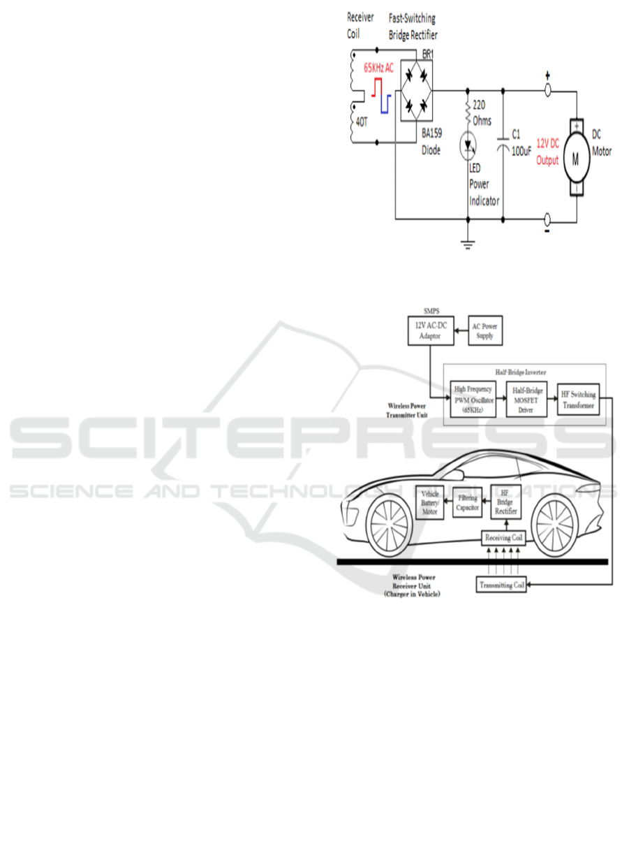
4.2 Receiver Subsystem
The receiver subsystem consists of a receiver coil
placed underneath the vehicle, designed to capture the
electromagnetic energy emitted by the transmitter
coil. The received high-frequency AC voltage is then
rectified using a high-speed bridge rectifier,
implemented with BA159 fast-switching diodes. This
rectifier efficiently converts the AC signal into DC
power, which is further stabilized by a filtering
capacitor to minimize voltage fluctuations.
The resultant 12V DC output can be used in two
ways:
1. Directly powering the vehicle’s motor,
enabling seamless movement without
relying on battery storage.
2. Charging the vehicle’s onboard battery,
ensuring sustained energy availability even
when the vehicle moves out of the charging
zone.
To enable real-time monitoring and automated
billing, a current sensor and NodeMCU
microcontroller are incorporated into the receiver
subsystem. The NodeMCU, equipped with Wi-Fi
capabilities, collects power consumption data and
transmits it to a centralized billing system.
Additionally, an RFID module is used to identify
individual vehicles, ensuring that energy costs are
accurately assigned to the respective users. Figure 3
shows the Block Diagram of the Proposed System.
Before that the Figure 2 shows the Receiver Circuit
Diagram to understand the concept of the Receiver
Subsystem.
Figure 2: Receiver Circuit Diagram.
Figure 3: Block Diagram of the Proposed System.
4.3 Key Components and
Functionalities
a) AC Power Supply: Provides 220V AC to power
the wireless transmitter.
b) AC-DC Adapter (SMPS): Converts 220V AC to
a stable 12V DC for circuit operation.
c) High-Frequency PWM Oscillator: Uses a U-
3525 IC to generate 65 kHz switching pulses, phase-
shifted by 90°, to control MOSFETs.
d) Driver MOSFETs (IRFZ44N): Alternately
switch to drive the high-frequency transformer,
creating an AC square wave.
ICRDICCT‘25 2025 - INTERNATIONAL CONFERENCE ON RESEARCH AND DEVELOPMENT IN INFORMATION,
COMMUNICATION, AND COMPUTING TECHNOLOGIES
764

e) High-Frequency Transformer: Converts DC to
high-frequency AC using a ferrite core for minimal
losses.
f) Half-Bridge Inverter: Integrates MOSFETs and
transformer to generate high-frequency AC for
transmission.
g) Transmitting Coil: Converts AC into
electromagnetic waves for inductive power transfer.
h) Receiving Coil: Captures electromagnetic waves
and converts them into high-frequency AC.
i) HF Bridge Rectifier: Uses fast-switching diodes
to convert AC to DC and to maintain voltage
feedback.
j) Filtering Capacitor: Smoothens the rectified DC
for stable power delivery to the EV battery or motor.
5 PCB DESIGN AND
IMPLEMENTATION
PCB designed in EasyEDA, hence, optimized layout,
low-power losses and good heat dissipation
performed. Schematic capture, placement of
components, routing, thermal considerations, etc.
A. Design Considerations
So, to get the most potential out of this, the PCB
layout included:
Parasitic Effects Minimization: High-frequency
signal paths were laid out to decrease parasitic
inductance and capacitance, which can lead to
spurious oscillations and unwanted signal distortions.
Design to Reduce Electromagnetic Interference
(EMI): a ground plane which provides
electromagnetic compatibility (EMC) helping to
minimize noise is also used that enhances stable
operation of the SG3525 PWM controller circuit and
MOSFET driver circuit.
Thermal Management: Given the other high-
power components in the design, including the
IRFZ44N MOSFETs and the rectifier diodes, careful
placement of components, copper traces, and thermal
vias was taken into account to dissipate heat
optimally.
Compact Layout: The design kept a compact
form factor by providing sufficient clearance between
high-voltage and low-voltage sections to avoid arcing
and leakage currents.
5.1 Challenges Faced and Solutions
1. High-Frequency Noise and EMI Issues:
o Challenge: The presence of high-frequency
switching (65 kHz) led to electromagnetic
interference (EMI), potentially affecting
sensitive components.
o Solution: Shielding techniques, proper trace
spacing, and the inclusion of decoupling
capacitors were implemented to mitigate
noise.
2. Thermal Dissipation of MOSFETs and
Rectifiers:
Issue: Continuous operation produces
substantial heat on the MOSFETs and
rectifier diodes.
Solution: Added heat sinks and larger
copper pour areas to reduce heat generation
and thermal runaway.
3. Efficient Coil Integration with PCB:
Issue: To minimize resistance and inductive
losses when interfacing the PCB with the
transmitter coil.
Wide, low-resistance traces and high-
current-rated connectors were used to ensure
efficient power transfer.
5.2 Final Implementation and Testing
Once the PCB was fabricated and assembled,
extensive testing was conducted to validate its
performance:
Continuity and Isolation Testing: Ensured
that all traces were correctly routed and no
unintentional short circuits existed.
Signal Integrity Verification: Oscilloscope
measurements confirmed that the PWM
signals maintained their expected frequency
and duty cycle.
Load Testing: The system was tested under
various load conditions to analyze power
efficiency, heat dissipation, and overall
stability. Figure 4 shows PCB Layout.
Figure 4: PCB Layout.
Dynamic Wireless Charging for E-Vehicles
765

6 RESULTS AND ANALYSIS
The experimental and computational analyses of the
dynamic wireless charging system were conducted,
focusing on key electrical parameters such as
inductance, capacitance, and resonance frequency.
The final values obtained on Table 1are tabulated
below:
Table 1: Calculated Electrical Parameters.
Paramete
r
S
y
mbol Value Unit
Coil Diamete
r
d
3.5 - 4.5 inches
Coil Length l
0.393 –
5.0
inches
Number of
Turns
n 100 - 120 -
Inductance L
1475.9 -
3014
µH
Capacitance C
3.30 -
1500
pF
Resonant
Frequenc
y
F
72.0 –
75.18
kHz
Oscillator
Frequency
Range
F_range 68 – 89.3 kHz
Resistance R 19 - 21
k
Ω
Dead Time
Resistance
R_D 0 Ω
6.1 Observations and Key Findings
Inductance adjusting: We computed in
this sub-chapter the inductance calculates
for the coils whereby we found that the
inductance goes from 1475.9 µH
and will
reduce up to 3014 µH depending on what
number of turns and dimensions of the
different coils are aligned. This will
contribute to
effective inductive power
flow for dynamic wireless charging.
Oscillator Stability: The
specified
frequency range of 68 – 89.3 kHz for the
oscillator allows an adaptive margin to
compensate for component tolerances and
environmental variations.
Low
Dead Time Resistance: The dead-
time losses in the oscillator circuit are
minimized with R_D = 0 Ω, allowing for
good power conversion efficiency.
The coil design was adapted to allow
for
maximum inductance without
compromising power.
Precision Frequency Tuning: The
frequency parameters used in fine-tuning
ensure almost all energy lost is minimized,
allowing for optimal resonance conditions
for inductive power
transfer.
Data up to October 2023 for
Sensing
Mechanism-based Automatic
Alignment System for Efficient
Charging: In proximity IR sensors-based
automatic alignment adjustment system
initiated for achieving alignment as
minimum energy transfer losses through
misalignment boosts up alignment
between transmitter and receiver coil for
higher power transfer efficiency.
Real-Time Billing Approach for Each
Vehicle: Robustness of energy
consumption is tracked using a current
sensor and image processing-based billing
system for accurate identification helping
in payment automation for dynamic
wireless charging
in fair and accurate
manner.
REFERENCES
A Review of Dynamic Wireless Charging Technologies for
Electric Vehicle Applications by Gao, S., Chen, Y., Mi,
C., & Jiang, J. (2017). In Proceedings of the IEEE
Transportation Electrification Conference and Expo
(ITEC), Asia-Pacific.
Design and Analysis of a Dynamic Wireless Charging
System for Electric Vehicles by Meng, Y., & Wang, W.
(2018). Energies, 11(6), 1370.
Dynamic Wireless Power Transfer System for Electric
Vehicles: Design, Implementation, and Experimental
Results by Mi, C., Gao, S., Zhang, W., & Zhang, Y.
(2017). IEEE Transactions on Power Electronics,
32(10), 7661-7675.
Dynamic Wireless Charging for Electric Vehicles: A
Review of Technologies and Challenges by Chen, Y.,
Gao, S., Li, X., & Mi, C. (2019). IEEE Transactions on
Transportation Electrification, 5(4), 1103- 1122.
Dynamic Wireless Charging System for Electric Vehicles:
Design, Analysis, and Optimization by Wang, S., Liao,
W., He, C., Zhang, Q., & Li, W. (2020). IEEE
Transactions on Power Electronics, 35(1), 341- 355.
Dynamic Wireless Charging Systems: Technologies, Key
Challenges, and Future Trends by Zhao, C., Chen, Q.,
& Cheng, M. (2020). IEEE Transactions on Industrial
Electronics, 67(11), 9413-9426.
Modelling and Analysis of Dynamic Wireless Charging
Systems for Electric Vehicles by Jiang, J., Gao, S., Li,
X., & Mi, C. (2016). IEEE Transactions on Power.
Performance Analysis of Dynamic Wireless Charging
Systems for Electric Vehicles by Li, X., Chen, Y., Mi,
C., & Gao, S. (2018). IEEE Transactions on Industrial
Electronics, 65(5), 3945-3956.
ICRDICCT‘25 2025 - INTERNATIONAL CONFERENCE ON RESEARCH AND DEVELOPMENT IN INFORMATION,
COMMUNICATION, AND COMPUTING TECHNOLOGIES
766
