Grid‑Connected Solar Farms with Dynamic Reserve Power Point
Tracking
J. Sree Ranganayakulu, Y. Sreeya, B. Vishnu Vardhan, G. Sowmya and T. Vinay
Department of EEE, Annamachrya Institute of Technology and Sciences, Rajampet, Andhra Pradesh, India
Keywords: Adaptable Power Regulation, Power System Assistance, Peak Power Output, Uneven Irradiance Distribution,
Solar Energy Farm, Available Power Capacity, Sub‑Optimal Power Point Management, Artificial Neural
Network (ANN).
Abstract: The RPPT methodology permits dynamic Reserve of Power control for grid-connected Solar Farms, assuring
the requisite Reserve of Power to sustain the grid and elevated PV power intrusion. Using a voltage controller
based on a model and Model Predictive Control (MPC) to control PV voltage and inductor current, the
algorithm switches the point of operation between two preset values within the PV curve. The RPPT
methodology is tested in settings of partial shade, fluctuating power reference, and steady-state performance.
It uses MPP information to control PV reserve power. The algorithm tracks MPP under partial shading,
provides grid frequency support, reduces DC-link capacitor stress, and improves system reliability. It operates
in MPPT, FPPT, or RPPT modes to maintain desired Power Reserve, offering advantages over traditional
methods, enabling flexible power injection and grid frequency support.
1 INTRODUCTION
Reserve Power Point Tracking (RPPT) is introduced
as a new algorithm for controlling power output from
grid-connected PV systems. Unlike traditional
MPPT, RPPT addresses modern grid requirements by
providing ancillary services like frequency regulation
and stable power injection. Key benefits of RPPT
over existing Flexible Power Point Tracking (FPPT)
methods:
No additional hardware needed: Avoids costs
associated with measurement-based FPPT.
• Robust without PV models: Operates
effectively without relying on potentially
inaccurate models.
• Handles partial shading: Effectively tracks
the global Maximum Power Point
• (MPP) even with multiple peaks due to
shading.
• Fast dynamic response: Crucial for grid
frequency support.
• Easily implemented: Requires no hardware
modifications to existing PV inverters.
RPPT's "sweeping" action dynamically switches
the PV system's operational point on the PV curve
between two voltages, providing continuous MPP
tracking, precise power control, and fast dynamic
response.
The RPPT algorithm's use of an Artificial Neural
Network (ANN) controller is not mentioned in the
text. ANNs are not included in the RPPT method that
has been explained, but they may be utilized in other
areas of PV system control. The use of ANNs to
improve RPPT performance may be investigated in
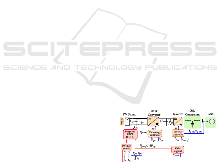
future studies. The control diagram for the current
RPPT for PV plants is displayed in Figure 1.
Figure 1: Control Schematic of the PV Plant's Current Rppt.
202
Ranganayakulu, J. S., Sreeya, Y., Vardhan, B. V., Sowmya, G. and Vinay, T.
Grid-Connected Solar Farms with Dynamic Reserve Power Point Tracking.
DOI: 10.5220/0013880100004919
Paper published under CC license (CC BY-NC-ND 4.0)
In Proceedings of the 1st International Conference on Research and Development in Information, Communication, and Computing Technologies (ICRDICCT‘25 2025) - Volume 2, pages
202-207
ISBN: 978-989-758-777-1
Proceedings Copyright © 2025 by SCITEPRESS – Science and Technology Publications, Lda.
2 PV SYSTEM CONNECTED TO
THE GRID
A PV system connected to the grid with two stages
uses the suggested RPPT algorithm. Two power
converters are part of this setup:
• Photovoltaic-side DC-DC boost
conversion.
• Grid-side three-phase DC-AC converter.
• A DC-link capacitor connecting the
converters.
2.1 Grid Support
• The system has a "grid support block" that
adjusts the power reference based on grid
frequency changes.
• Grid support functions give a power
reference to the RPPT algorithm.
2.2 RPPT Algorithm
It establishes the PV array's reference voltage. A
voltage controller based on a model is used to regulate
this voltage. By controlling the inductor current and
DC-DC boost converter switching, Model Predictive
Control (MPC) manages the PV output. While
keeping the average DC-link voltage constant, the
three-phase inverter sends the PV power to the grid.
To summarize, the DC-DC boost converter controls
the PV output based on the RPPT's voltage reference.
In addition to managing the DC link, the inverter
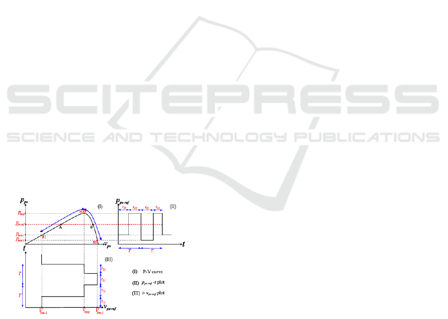
supplies electricity to the grid. In figure 2, it is
depicted.
Figure 2: Operating Principle of RPPT.
3 EXISTING METHODOLOGY
Dynamic Reserve Power Point Tracking (DRPPT) is
an algorithm that controls the power output of solar
panel systems to maintain a desired power reserve. It
operates by either following a power reference (Ppv-
ref) or targeting a specific percentage of power
reserve (%Pref).
3.1 Key Features of DRPPT
• Regular scanning: The algorithm scans
the power-voltage curve between two
voltage limits (Vlim-1 and Vlim-2) to find
the Maximum Power Point (MPP), even
under changing conditions.
• Recording data: During the scan, voltage
and power are recorded. The algorithm
spends calculated amounts of time at
voltage limits and briefly at the MPP using
energy balance equations to match the
desired average power output.
• Simplified process: If the target power is
within a specific range, the system only
scans between two points, simplifying the
process.
• Handling delays: The algorithm accounts
for small system response delays.
• Partial shading management: By
including the global MPP in the scanning
range, RPPT effectively identifies the
highest power point.
• Grid support: RPPT can actively control
the output power to meet the grid
frequency requirements according to the
specific grid requirements (such as the
South African standard), and thus can
contribute to supporting and stabilizing
grid frequency.
4 PROPOSED METHODOLOGY
4.1 Artificial Neural Networks (ANNs)
• Structure: Inspired by the human brain,
consisting of interconnected neurons in
layers (input, hidden, output).
• Learning: Connections between nodes have
weights adjusted during learning, enabling
adaptation to new data.
4.2 Algorithm of DRPPT
DRPPT is an advanced technique for controlling
power reserves in grid-connected solar farms that
Grid-Connected Solar Farms with Dynamic Reserve Power Point Tracking
203
also takes energy generation into account. DRPPT
general algorithm:
1. Initialization
o Set the desired power reserve level
based on grid requirements.
o Initialize the system parameters,
including solar irradiance,
temperature, and panel
characteristics.
2. Data Acquisition
o Keep an eye on the photovoltaic
(PV) system's output voltage (V),
current (I), and power (P) at all
times.
o Measure environmental conditions
like solar irradiance and
temperature.
3. Maximum Power Point Estimation
o with the given conditions, implement
an MPPT algorithm (like Perturb
and Observe/Incremental
Conductance) to determine the PV
system's Maximum Power Point
(MPP).
4. Reserve Power Calculation
o Determine the reserve power by
subtracting the intended power
output from the MPP power.
o Ensure the reserve power meets the
grid's requirements for stability and
frequency regulation.
5. Dynamic Adjustment
o Maintain the intended power
production while saving the
calculated power by adjusting the
PV system's operating point.
o When operating below the MPP,
employ a flexible power point
tracking (FPPT) strategy.
1. Grid Synchronization
o Make sure the power output's
voltage, frequency, and phase are
all in sync with the grid.
o For grid compatibility, convert DC
power to AC electricity using
inverters.
2. Feedback and Optimization
o Continuously monitor the system's
performance and environmental
conditions.
o Update the algorithm parameters
dynamically to adapt to changing
conditions, such as partial shading
or grid frequency deviations.
3. Fault Handling
o Detect and isolate faults in the PV
system to prevent disruptions.
o Reconfigure the system to maintain
optimal performance.
This algorithm ensures that the PV system can
provide a stable power reserve while maximizing
energy efficiency.
4.3 Benefits of ANN Controllers
1. Adaptability: Learn and adapt to changing
conditions.
2. Non-linearity: Model complex, non-linear
relationships.
3. Fault Tolerance: Handle noisy or
incomplete data robustly.
4. Parallel Processing: Process multiple
inputs concurrently for faster computations.
5. Versatility: Used in diverse fields like
medical sciences, engineering, robotics,
finance, and speech recognition.
4.4 Using ANNs in MATLAB
• Neural Network Toolbox: Comprehensive
toolbox for creating, configuring, training,
simulating, and visualizing ANNs.
• Functions: Define network parameters, use
various training algorithms, predict outputs
for new inputs, and evaluate performance.
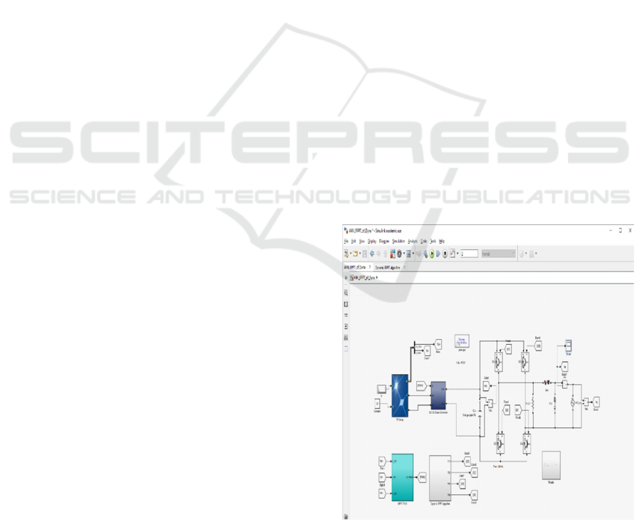
Figure 3: MATLAB Model of DRPPT Using ANN
Controllers.
ICRDICCT‘25 2025 - INTERNATIONAL CONFERENCE ON RESEARCH AND DEVELOPMENT IN INFORMATION,
COMMUNICATION, AND COMPUTING TECHNOLOGIES
204
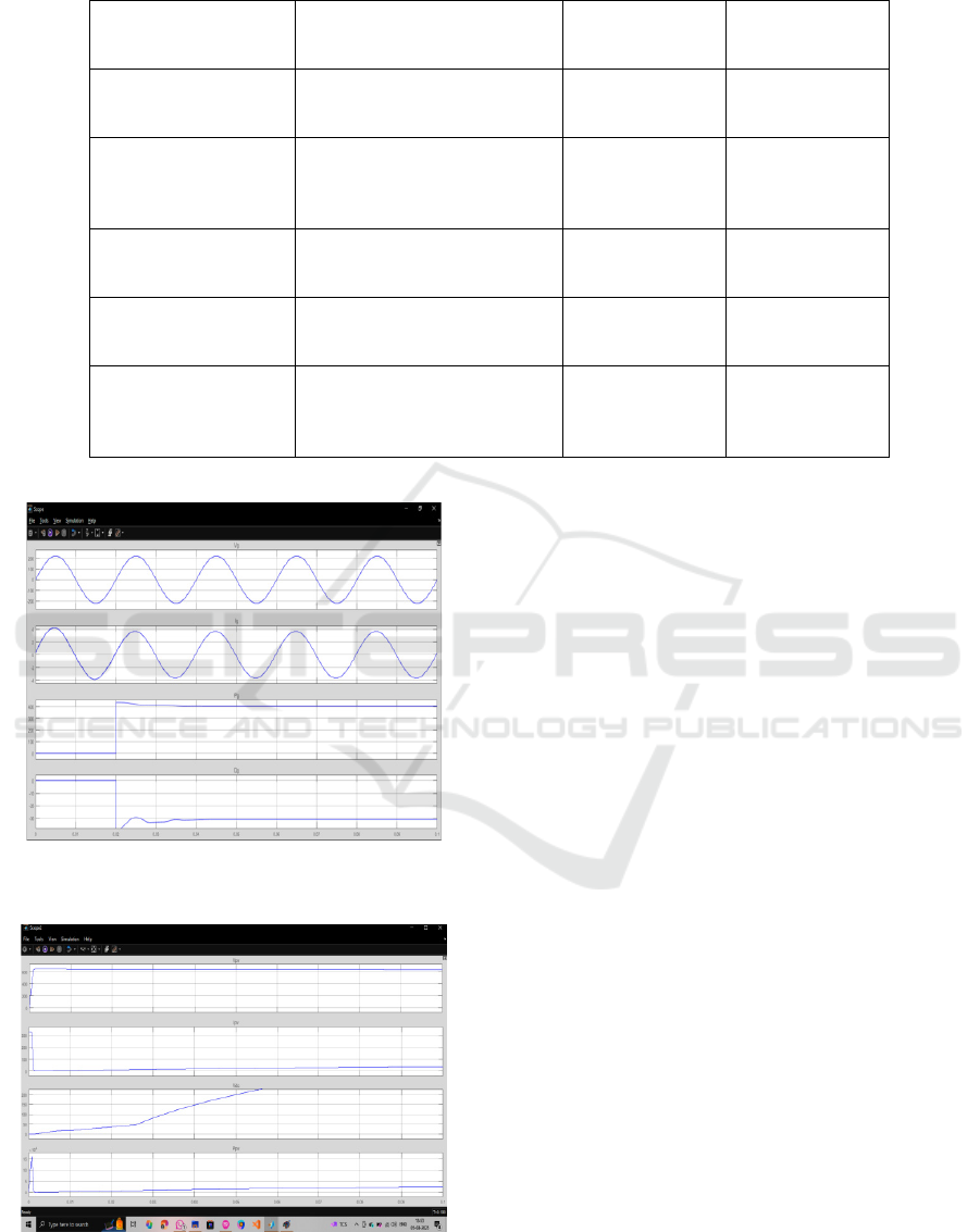
Table 1: Differences Between Existing and Proposed Methodology.
Feature
Existing Methodologies
(Measurement/Estimation
Based
)
Proposed RPPT
Methodology
Potential ANN
Integration with
RPPT
Hardware
Often requires additional
sensors/hardware
No additional
hardware
re
q
uire
d
Could potentially
reduce sensor
needs
Model Dependency
Relies on PV models,
susceptible to inaccuracies
Model-free,
robust to aging
Could improve
model-based
estimation if
neede
d
Dynamic Response
Can be slow, especially with
sensorless methods
Fast dynamic
response
Could enhance
prediction and
control s
p
ee
d
Partial Shading
Challenges in identifying
GMPP
Effectively
handles partial
shadin
g
Could improve
GMPP
identification
Implementation Can be complex
Simple, control-
based
Could simplify
control logic in
complex
scenarios
Figure 4: Output Voltage and Current Wave Forms of
DRPPT Using ANN Controllers.
Figure 5: Output Power Wave Forms of DRPPT Using
ANN Controllers.
5 OUTPUT WAVE FORM
DESCRIPTION
When solar panels generate electricity, they produce
direct current (DC), which is like water flowing
steadily in one direction through a pipe. However, the
electrical grids and most appliances use alternating
current (AC), where the flow of electricity alternates
direction. To make this transition, the system uses an
apparatus known as an inverter. The inverter
transforms the converting DC power to AC, creating
a waveform that alternates back and forth, similar to
the back-and-forth flow of water in a pipe.
Table 1
shows the Differences Between Existing and
Proposed Methodology.
Initially, the AC waveform created by the inverter
might look a bit blocky or choppy, which isn’t ideal
for the grid. To smooth it out and make it more like
the clean sinusoidal waves we want, the system uses
special filters. These filters remove any unwanted
noise or distortions, leaving behind a nice, smooth
wave. This clean waveform can now be sent to the
electrical grid or used by appliances. The peak values
of output voltage (V
g
) waveform are +2.200e+02 and
-2. 200e+02.Simillarly the output waveforms current
(I
g
) are 3.666e+00 and -3.666e+00, active power (P
g
)
are 4.033e+02 and reactive power (Q
g
) are -
3.105e+01.
To ensure the generated AC power can merge
seamlessly with the grid, the system fine-tunes the
waveform. It aligns the wave's rhythm, including its
voltage, frequency, and phase, with the grid's
Grid-Connected Solar Farms with Dynamic Reserve Power Point Tracking
205

standards. This process ensures everything works
together smoothly, like synchronized dancers moving
in unison. The pv values of the output wave forms are
V
pv
=6.447e+02, Ipv=3.325e+01, Vdc=2.975e+01,
Ppv=2.130e+04.
However, solar farms face challenges like sudden
changes in sunlight or shifts in grid requirements.
Dynamic algorithms like RPPT (Reserve Power Point
Tracking) help adjust the waveforms quickly to meet
these changing needs. This ensures that the system
can maintain steady power output, even under
varying conditions, and support the grid efficiently.
It’s a seamless blend of technology and adaptability
to keep the power flowing.
6 SIMULATION RESULTS
Simulation results on a three-phase system also
showed the RPPT algorithm's effectiveness at high
power levels. The tests covered various conditions,
including partial shading, MG predictive capabilities
for enhanced Maximum Power Point (MPP) tracking,
updated output to maintain grid stability under
simulated grid frequency changes, and transient
condition tests confirming seamless sequence to
Utility Mode.
Figure 3 shows the MATLAB model of
DRPPT using ANN controllers.
The results presented in figures 4 and 5 suggest
that RPPT is suitable for large-scale solar power
stations. Artificial Neural Networks (ANNs) to
improve the performance of the proposed algorithm,
such as enhancing the precision of power tracking, the
contribution to the grid, reliability, and optimizing the
control.
But while adding ANNs seems like an attractive
option, it would also add considerable complexity to
the system, so the associated benefits need to be
authenticated and weighed against the additional
costs and effort required. However, the simulations
indicated that ANNs have advantages for large-scale
solar plants in particular.
7 CONCLUSIONS
RPPT is a novel design approach for solar power
plants that maximizes the capacity it can output and
incorporates flexible supply to the grid. It has three
modes of operation: maximum power, fixed amount
of power, or reserve for grid needs. When some
panels are shaded, RPPT has demonstrated its ability
to identify the ideal power point. Further integration
on this version to include Artificial Neural Network
(ANN) can prove beneficial in ensuring accuracy of
power tracking, adaptation to changing conditions,
noisy data handling and prediction of future power
output. But the addition of ANNs to systems would
also enhance complexity. RPPT, for now, works well
without ANNs simple solutions at their best.
REFERENCES
A. Cabrera-Tobar, E. Bullich-Massagué, M. Aragüés-
Peñalba, and O. Gomis-Bellmunt, “Review of advanced
grid requirements for the integration of large scale
photovoltaic power plants in the transmission system,”
Renewable Sustain. Energy Rev., vol. 62, pp. 971–987,
Sep. 2016.
C. Yongning, L. Yan, L. Zhen, C. Ziyu, and L. Hongzhi,
“Study on grid-connected renewable energy grid code
compliance,” in Proc. IEEE Sustain. Power Energy
Conf., 2019, pp. 72–75.
D. W. Gao, E. Muljadi, T. Tian, and M. Miller,
“Comparative analysis and considerations for PV
interconnection standards in the United States and
China,” Nat. Renewable Energy Lab., Feb. 2017.
Accessed: May 14, 2022. [Online] Available:
https://www.nrel.gov/docs/fy17osti/64226.pdf
H. Beltran, E. Bilbao, E. Belenguer, I. Etxeberria-Otadui,
and P. Rodriguez, “Evaluation of storage energy
requirements for constant production in PV power
plants,” IEEE Trans. Ind. Electron., vol. 60, no. 3, pp.
1225–1234, Mar. 2013.
H. D. Tafti, G. Konstantinou, J. E. Fletcher, L. Callegaro,
G. G. Farivar, and J. Pou, “Control of distributed
photovoltaic inverters for frequency support and system
recovery,” IEEE Trans. Power Electron., vol. 37, no. 4,
pp. 4742–4750, Apr. 2022.
M. A. Danandeh and S. M. Mousavi G., “Comparative and
comprehensive review of maximum power point
tracking methods for PV cells,” Renewable Sustain.
Energy Rev., vol. 82, pp. 2743–2767, Feb. 2018.
S. Hanley, “Solar power prices fall as installations rise,”
Sep. 23, 2022. Accessed: Oct. 26, 2022. [Online].
Available: https://cleantechnica.com/
2022/09/23/solar-power-prices-fall-as-installations-
rise/ [2] “Renewable 2022 global status report,” 2022.
Accessed: Oct. 22, 2022. [Online]. Available:
https://www.ren21.net/gsr-2022/
S. Chen, T. Zhang, H. B. Gooi, R. D. Masiello, and W.
Katzenstein, “Penetration rate and effectiveness studies
of aggregated BESS for frequency regulation,” IEEE
Trans. Smart Grid, vol.7, no.1, pp.167–177, Jan2016.
V. Saxena, N. Kumar, B. Singh, and B. K. Panigrahi, “An
enhanced multilayer GI based control for grid
integrated solar PV system,” in Proc. IEEE Int. Conf.
Power Electron., Drives Energy Syst., 2020, pp. 1–6.
[9] Australia/New Zealand Standard AS/NZS 4777,
“Grid connection of energy systems via inverters:
Inverter requirements,” 2020. Accessed: Oct. 19,
ICRDICCT‘25 2025 - INTERNATIONAL CONFERENCE ON RESEARCH AND DEVELOPMENT IN INFORMATION,
COMMUNICATION, AND COMPUTING TECHNOLOGIES
206

2022. [Online] Available: https://www. standards.
org.au/standard scatalogue/sa-snz/other/el-042/as-
slash-nzs--4777-dot-2-colon-2020
V. Saxena, N. Kumar, B. Singh, and B. K. Panigrahi, “A
rapid circle centre-line concept-based MPPT algorithm
for solar photovoltaic energy conversion systems,”
IEEE Trans. Circuits Syst. I, Reg. Papers, vol. 68, no.
2, pp. 940–949, Feb. 2021.
V. Saxena, N. Kumar, B. Singh, and B. K. Panigrahi, “A
voltage support control strategy for grid integrated solar
PV system during abnormal grid conditions utilizing
interweaved GI,” IEEE Trans. Ind. Electron., vol. 68,
no. 9, pp. 8149–8157, Sep. 2021.
V. Saxena, N. Kumar, B. Singh, and B. K. Panigrahi, “An
MPC based algorithm for amultipurpose grid integrated
solar PV system with enhanced power quality and PCC
voltage assist,” IEEE Trans. Energy Convers., vol. 36,
no. 2, pp. 1469–1478, Jun. 2021.
Y. Yang, P. Enjeti, F. Blaabjerg, and Hwan, “Wide-scale
adoption of photovoltaic energy: Grid code
modifications are explored in the distribution grid,”
IEEE Ind. Appl. Mag., vol. 21, no. 5, pp. 21–31,
Sep./Oct. 2015.
Grid-Connected Solar Farms with Dynamic Reserve Power Point Tracking
207
