
Thermal Performance Enhancement of Earth Tube Heat Exchanger
R. Vasanthakumar, P. Murugesan, S. Balamurugan, K. Akash, K. Dharunesh and K. Tamilselvi
Department of Mechanical Engineering, K.S.R. College of Engineering, Tiruchengode‑637215, Tamil Nadu, India
Keywords: Air Low Optimization, CFD Simulation, Cooling Air, Cop, etheGeothermal Energy, HVAC System, Natural
Convection.
Abstract: The fabrication of an earth tube heat exchanger involves designing an efficient system for natural cooling or
heating using underground pipes. The system circulates air through buried tubes, leveraging the earth's stable
temperature to cool or warm the air, reducing reliance on traditional HVAC systems. Aluminium tube of
length 21 m, 205 w/mk thermal conductivity, results in COP of 1.5 to 2.9.A copper tube of length 15m, 385
w/mk thermal conductivity results in COP 1.3 to 3.2. A 15m copper serpentine tube with thermal conductivity
of 385 W/m·K exhibits a COP improvement from 1.3 to 3.2 at increased inlet velocity. This suggests that
increased fluid velocity enhances the efficiency, heat transfer, and thermal performance of the system, hence
the earth tube heat exchanger becomes more efficient. The result indicates that the analysed earth tube heat
exchanger with copper serpentine tube and calculated COP will significantly improve the thermal
performance of an earth tube heat exchanger.
1 INTRODUCTION
Leveraging the natural thermal characteristics of the
Earth, Earth Tube Heat Exchanger (ETHE) is an
alternative to efficient temperature control in this
contemporary period. Air is supplied through copper
tubing of 15 m length and 385 W/mK thermal
conductivity at varying velocities of 1, 2, 3, and 4 m/s
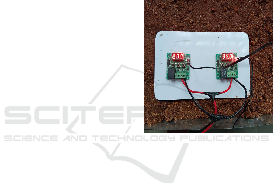
in a soil environment with a blower for 12 V, 0.45
amps DC. This system employs the earth's perpetual
temperature of 26.2 °C to generate outlet
temperatures at similar rates of 33.6 °C, 34.5 °C,
34.8 °C, and 35.2 °C.
Observation and system control based on desired
and ambient temperature levels allow a relay and
temperature sensors to reduce the use of conventional
heating and cooling systems and significantly reduce
energy consumption and costs. By making use of
constant earth temperatures underground to provide
winter heat and summer coolness, earth-air heat
exchangers (ETHE) reduce building energy
consumption. Design, performance, and ground
temperature fluctuations of ETHE are the focus of
this research, its ability to lessen greenhouse gas
emissions and energy consumption, especially in
India with a COP of 1.5(Shams Forruque
Ahmed,et.al., 2021). Heat Exchanger in conjunction
with natural ventilation to create the best of indoor
conditions with reduced costs and energy use. It will
give the heat transfer rate to 600 watts (Giouli
Mihalakakou, et.al.,2022). An Earth-to-Air Heat
Exchanger (ETHE) utilizes ground thermal energy to
provide heat in winters with higher efficiency.
Simulation using CFD for a 13-meter pipe indicated
higher heat transfer and efficiency with lower
velocities of air in winter in Bhopal with a cop of
1.8(Ahmed A Serageldin, et.al.,2016). (GAHE)
employs geothermal energy in effective cooling and
heating. Its performance was simulated in this work
with ANSYS Fluent and SOLIDWORKS, and its
COP values and best temperatures were between
0.5
to 1.3(Hadi,et.al., 2024). The Earth-Air Heat
Exchanger (EHX) improves home comfort and
conserves energy. A 2021 Baghdad experiment
revealed 12.3°C increase in January and 17.2°C in
June demonstrated that it was extremely effective
(Lattieff,et.al., 2022).
2 RELATED WORKS
Number of papers published on this topic in the last
five years is more than 95 papers in IEEE Xplore, 60
papers in Google Scholar, 110 papers in Academia. A
soil-to-air heat exchanger (EAHE) using an
evaporative cooler can minimize pipe length by as
78
Vasanthakumar, R., Murugesan, P., Balamurugan, S., Akash, K., Dharunesh, K. and Tamilselvi, K.
Thermal Performance Enhancement of Earth Tube Heat Exchanger.
DOI: 10.5220/0013877100004919
Paper published under CC license (CC BY-NC-ND 4.0)
In Proceedings of the 1st International Conference on Research and Development in Information, Communication, and Computing Technologies (ICRDICCT‘25 2025) - Volume 2, pages
78-82
ISBN: 978-989-758-777-1
Proceedings Copyright © 2025 by SCITEPRESS – Science and Technology Publications, Lda.
much as 93.5%. Surface-to-volume ratio, airflow rate,
and pipe diameter are the most significant factors
influencing outlet temperature with a COP of
2.5(Benzaama, M. H.,et.al., 2022). Earth tubes are an
environmentally friendly method of saving energy
expenses through cooling houses and warming
houses during winter, with studies showing notable
savings in energy and a smaller climate footprint with
a COP of 1.9(Sofyan,et.al., 2024).Earth tube heat
exchangers use geothermal energy for heating and
cooling, providing a green HVAC system that is
energy-saving and simple to install achieves 40% air
ventilation. Optimization of earth-air heat exchanger
(EAHE) systems involves pipe properties and airflow
rate 4 m/s, and also exploration of the impact of soil
density and moisture on performance temperature up
to 35 degree Celsius(Omer AM , 2008).Earth tube
heat exchangers energy- efficient heating and
cooling, satisfying HVAC requirements effectively
with COP of 1.9(Esen H,et.al.,2007).The research
maximizes the Naples, Italy Earth to Air Heat
Exchanger (EAHX) and discovers that an ETHE of
diameter 0.1 m, 1.5 m/s velocity, and length 50 m has
maximum output temperatures 40% more
efficient(Givoni B, et.al.,1981). Earth-air tunnel
ventilation relies on constant ground temperatures to
control air, yet soil- atmosphere exchanges may be
underestimated, and this leads to performance
overestimation. Good simulations are highly critical
max COP of 2.5(Deshmukh MK, et.al., 1991).
Inference: From the previous findings, it is concluded
that
the
use
of an
Aluminium tube
will result in
less COP due to less thermal conductivity and poor
pipe design. The aim of this is to enhance the thermal
performance of an earth tube heat exchanger by using
copper tube which having high thermal conductivity
and serpentine (design)
3 MATERIALS AND METHODS
Indian earth tube heat exchangers are affordable,
offering cooling and heating. BMR-HVAC in
Faridabad saw temperature fluctuations of 3.93°C to
12.6°C in summer and 6°C to 10°C in winter (Esen
H,et.al., 2017). Aluminium tube of length 21m, 205
w/mk thermal conductivity, results in COP of 1.5 to
2.9. A copper waveflow tube of length 15m, 385
w/mk thermal conductivity results in COP of 1.3 to
3.2. Earth-air heat exchangers utilize earth
temperatures to provide cooling and heating by
minimizing energy utilization. Ventilation
Information Paper prescribes their operation and
specifications (Lucia U,et.al., 2017).
3.1 Flowchart/Process
Steps/Method/Block Diagram
An Earth Tube Heat Exchanger employs buried pipe
to passively control air temperature. External fresh air
is pulled through the pipe and cooled or heated by the
soil seasonally. The conditioned air is fed to the
ventilation system in the building, creating an energy-
saving means of creating comfortable indoor
temperatures.
Figure 1: Temperature Monitoring Setup.
SSPL Tool: The ANSYS Fluent R19.0 CFD
simulation of a serpentine heat exchanger used a k-ε
turbulence model and tetrahedral meshing. Velocity
inlet, pressure outlet, and no-slip walls were used by
the solution that used second-order upwind
discretization and 1e-6 convergence. Results
indicated pressure drop (103618 Pa to 100745 Pa),
temperature range (299.47 K to 350 K), and
maximum velocity of 55.69 m/s, which indicated
design optimization.
Design Calculation
Amount of heat transfer Q = mCpdt (J) (1)
Coefficient of performance Q/W (2)
By using above these formulas, we found out the
length of ETHE. Calculation results are given below.
Thermal Performance Enhancement of Earth Tube Heat Exchanger
79
4 RESULTS
A copper tube of length 15m, 385 w/mk thermal
conductivity results in COP 1.3 to 3.2. Thus the data
indicates that with the rise in inlet velocity,
temperature, heat flow, and COP all rise. This
indicates that the efficiency and ability of heat
transfer of the system improve with higher fluid
velocity Table 2 This table illustrates the inlet
velocity (in m\s) and the associated temperature (in
°C). When the inlet velocity increases from 1 m/s to
4 m/s, the numerical solution output temperature
increases from 27.9°C to 32.7°C, proving the positive
correlation of inlet velocity and temperature. Table3
Inlet velocity rises from 1 m/s to 4 m/s, and heat flow
and COP are also increased. Heat flow is increased
from 332.8 W to 819.2 W, and COP is increased from
1.3 to 3.2, which indicates higher efficiency and heat
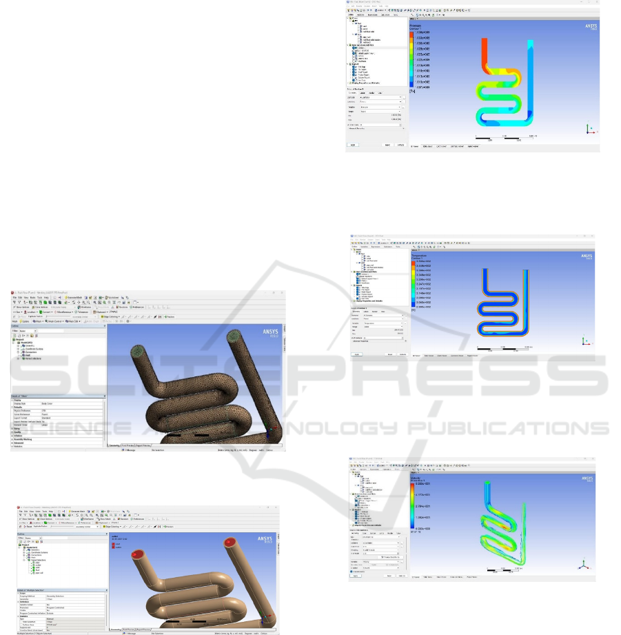
transmission at elevated velocities. Figure 2. The
picture depicts a helical pipe mesh in ANSYS Fluent
(R19.0), which is optimized for CFD simulation.
Figure 2: A helical pipe mesh in ANSYS Fluent (R19.0),
which is optimized for CFD simulation.
Figure 3: ANSYS Fluent Meshing (R19.0) with a piping
system ready to be used for CFD simulation, specifying
inlet, outlet, and boundary conditions for fluid flow or heat
transfer.
Figure 3 this figure depicts ANSYS Fluent Meshing
(R19.0) with a piping system ready to be used for
CFD simulation, specifying inlet, outlet, and
boundary conditions for fluid flow or heat transfer.
Figure 4. It shows pressure contours with numeric
values in Pascals (Pa), from about 1.010e+005 Pa up
to 4.036e+005 Pa, which suggests a fluid flow or heat
transfer calculation.
Figure 4: ANSYS Fluent Meshing (R19.0) with a piping
system ready to be used for CFD simulation, specifying
inlet, outlet, and boundary conditions for fluid flow or heat
transfer.
Figure 5: Temperature contour plot of fluid flow through a
serpentine tube. High temperatures (red) are at the walls,
and low temperatures (blue) are within the core flow,
showing heat transfer. Analysis enhances the analysis of
thermal performance and flow behaviour.
Figure 6: Velocity streamline plot of fluid flow through
serpentine pipe. Red indicates higher velocities in bends
and blue for low velocities in straight sections, which shows
flow behaviour and turbulence.
Figure 5. ANSYS Fluent (R19.0) CFD-Post and a
temperature contour plot of fluid flow through a
serpentine tube. High temperatures (red) are at the
walls, and low temperatures (blue) are within the core
flow, showing heat transfer. Analysis enhances the
analysis of thermal performance and flow behavior.
Figure 6. Velocity streamline plot of fluid flow
through serpentine pipe. Red indicates higher
velocities in bends and blue for low velocities in
ICRDICCT‘25 2025 - INTERNATIONAL CONFERENCE ON RESEARCH AND DEVELOPMENT IN INFORMATION,
COMMUNICATION, AND COMPUTING TECHNOLOGIES
80

straight sections, which shows flow behavior and
turbulence. Figure 7. This graph is depicted between
inlet velocity vs temperature output and heat flow.
Figure 7: Inlet velocity vs temperature output inlet velocity
vs heat transfer.
5 DISCUSSIONS
This project shows that the fluid flow velocity can be
enhanced in an Earth Tube Heat Exchanger with a
copper serpentine tube for greater heat transfer to
improve the Coefficient of Performance (COP) from
1.3 to 3.2. Copper's high thermal conductivity
improves efficiency, and the system is more energy
efficient and effective. The research maximizes the
Naples, Italy Earth to Air Heat Exchanger (EAHX)
and discovers that an ETHE of diameter 0.1 m, 1.5
m/s velocity, and length 50 m has maximum output
temperature (Inalli M,et.al., 2004). This research
analyzes the thermal efficiency of an Earth- to-Air
Heat Exchanger (EAHX) during warm weather. A 60
m long, 100 mm diameter model with 239 fins is
subjected to a temperature drop of 20.5°C (Wu W,
et.al., 2014).
Table 1: Input parameters.
S.NO INPUT PARAMETERS SYMBOL
S
VALUE
1 Inlet Temp T
in
35
2 Length of Tube L 15
3 Pipe wall Temp (below
5ft)
T
wall
25
4 Thermal conductivity of
the ai
r
K
air
0.0266
5 Thermal conductivity of
the pip
e
K
Pipe
385
6 Thermal capacity C
p
1006
7 Viscosity µ 0.000018
4
8 Density of air P 1.1465
9 Velocity of air v
air
1,2,3,4
The system's performance was analyzed under 72-
hour conditions of temperature fluctuation, COP, and
efficiency (Balbay A,et.al., 2010). This research
mimics a 45m, 0.08m diameter EATHE pipe 5m
deep, with air speed at 1 m/s. ANSYS and CFD
Fluent are used to model heat transfer and
temperature changes according to Bhopal's climate
from June 2016 to May 2017(Balbay A,et.al., 2010).
Table 1 shows the input parameters. Table 2
shows the inlet velocity (in m\s) and the associated
temperature (in °C). When the inlet velocity increases
from 1 m/s to 4 m/s, numerical solution output
temperature increases from 27.9°C to 32.7°C, proving
the positive correlation of inlet velocity and
temperature.
Table 2: Inlet velocity vs associated temperature.
S.
No
Inlet Velocity
(m/s)
Numerical Method
Output
Temperature
1 1 27.9
2 2 28.5
3 3 29.8
4 4 32.7
Table 3 shows the Inlet velocity rises from 1 m/s to 4
m/s, and heat flow and COP are also increased. Heat
flow is increased from 332.8 W to 819.2 W, and COP
is increased from 1.3 to 3.2, which indicates higher
efficiency and heat transmission at elevated
velocities.
Table 3: Inlet velocity, heat flow & COP.
S.
No
.
Inlet Velocity
(m/s)
Heat flow
(watt)
COP
1 1 332.8 1.3
2 2 486.4 1.9
3 3 691.2 2.7
4 4 819.2 3.2
6 SCOPE FOR FUTURE WORK
The future of Earth Tube Heat Exchangers lies in
increased efficiency through integration with
renewable power, better materials, and intelligent
automation. They can also be made suitable for urban
settings, tailored to particular climates, and integrated
with energy storage, and thus more scalable, cheaper,
and more sustainable.
Thermal Performance Enhancement of Earth Tube Heat Exchanger
81

7 CONCLUSIONS
It is observed that by increasing the velocity of the
inlet of the 15m copper serpentine tube, heat transfer
is increased dramatically, from 1.3 to 3.2. This
indicates that fluid velocity improves system and
thermal efficiency, thereby making the earth tube
heat exchanger more efficient.
REFERENCES
Ahmed A Serageldin, Ali K Abdelrahman, Shinichi
Ookawara Energy Conversion and management 122,
25-38, 2016.
Balbay A, Esen M. Experimental investigation of using
ground source heat pump system for snow melting on
pavements and bridge decks. Sci Res Essay
2010;5(24):3955–66.
Balbay A, Esen M. Temperature distributions in pavement
and bridge slabs heated by using vertical ground-source
heat pump systems. Acta Sci-Technol 2013;35(4):677–
85.
Benzaama, M. H., S. Menhoudj, A. M. Mokhtari, and M.
Lachi. "Comparative study of the thermal performance
of an earth air heat exchanger and seasonal storage
systems: Experimental validation of Artificial Neural
Networks model." Journal of Energy Storage 53 (2022):
105177.
Deshmukh MK, Sodha MS, Sawhney RL. Effect of depth
of sinking on thermal performance of partially
underground buildings. Int J Energy Res
1991;15(5):391–403.
Esen H, Inalli M, Esen M. Numerical and experimental
analysis of a horizontal ground-coupled heat pump
system. Build Environ 2007;42(3):1126–34.
Esen H, Inalli M, Esen M. A techno- economic comparison
of ground-coupled and air-coupled heat pump systems
for space cooling. Build Environ 2007;42(5):1955–65.
Esen H, Esen M, Ozsolak O. Modelling and experimental
performance analysis of solar-assisted ground source
heat pump systems. J Exp Theor ArtifIntell
2017;29(1):1–17.
Giouli Mihalakakou, Manolis Souliotis, Maria Papadaki,
George Halkos, John Paravantis, Sofoklis Makridis,
Spiros Papaefthimiou Renewable and Sustainable
Energy Reviews 155, 111921, 2022
Givoni B, Katz L. Earth temperatures and underground
buildings. Energy Build 1985;8(1):15–25.
Givoni B. Earth-integrated buildings an overview. Archit
Sci Rev1981;24(2):42– 53.
Hadi, Faeza Mahdi, Muntadher Hashim Abed, and Karrar
Abed Hammoodi. "Thermal Performance of Earth Air
Heat Exchanger for Geothermal Energy Application in
Hot Climate using CFD Simulation." Journal of
Advanced Research in Fluid Mechanics and Thermal
Sciences 115, no. 1 (2024): 99-117.
Inalli M, Esen H. Experimental thermal performance
evaluation of a horizontal ground-source heat pump
system. Appl Therm Eng 2004;24(1415):2219–2232.
Khatry AK, Sodha MS, Malik MAS. Periodic variation of
ground temperature with depth. Sol Energy 1978;2
Lattieff, Farkad A., Mohammed A. Atiya, Rudainah Ali
Lateef, Anmar Dulaimi, Muhsin J. Jweeg, Azher M.
Abed, Jasim M. Mahdi, and Pouyan
Talebizadehsardari. "Thermal analysis of horizontal
earth-air heat exchangers in a subtropical climate: An
experimental study." Frontiers in Built Environment 8
(2022): 981946.
Lucia U, Simonetti M, Chiesa G, Grisolia G. Ground-
source pump system for heating and cooling: review
and thermodynamic approach. Renew Sustain Energy
Rev 2017.
Omer AM. Ground-source heat pumps systems and
applications. Renew Sustain Energy Rev
2008;12(2):344–71.
Shams Forruque Ahmed, Suvash C Saha, JC Debnath, G
Liu, M Mofijur, Ali Baniyounes, SMEK Chowdhury,
Dai-Viet N Vo Environmental Chemistry Letters 19
(6), 4191-4210, 2021.
Sofyan, Sarwo Edhy, Teuku Meurah Indra Riayatsyah, Eric
Hu, Akram Tamlicha, Teuku Muhammad Reza Pahlefi,
and H. B. Aditya. "Computational fluid dynamic
simulation of earth air heat exchanger: A thermal
performance comparison between series and parallel
arrangements." Results in Engineering 24 (2024):
102932.
Wu W, You T, Wang B, Shi W, Li X. Simulation of a
combined heating, cooling and domestic hot water
system based on ground source absorption heat pump.
Appl Energy 2014; 126:113–22.
ICRDICCT‘25 2025 - INTERNATIONAL CONFERENCE ON RESEARCH AND DEVELOPMENT IN INFORMATION,
COMMUNICATION, AND COMPUTING TECHNOLOGIES
82
