
Method for Automated Forklift Pallet Transfer with Simple Camera
Calibration
Tibor Bataljak Savi
´
c, Kre
ˇ
simir Turkovi
´
c, Ian Petek and Damjan Mikli
´
c
Romb Technologies d.o.o., Marti
´
ceva 55, Zagreb, Croatia
Keywords:
Camera Calibration, RGB-D Image Processing, Pallet Pose Estimation, Automated Guided Vehicle, AGV,
Mobile Robot.
Abstract:
This paper describes a practical method for calibrating the camera pose for adaptive pallet pickup by automated
forklifts. Adaptive pickup is an important prerequisite for human-robot collaborative workflows. It enables
robots to handle pallets that have been incorrectly placed by humans. We propose a vision-based method
that estimates the pallet pose from RGB-D data and adapts the robot approach path accordingly. The vision
pipeline combines semantic segmentation of the RGB image with geometric analysis of the depth channel.
Precise camera pose calibration is fundamental for the accuracy of the whole pipeline. The method relies on
the known geometry of the forks and can be run on-line before every operation. This is important from a
practical point of view, as it compensates for small deviations that may occur due to vibrations during vehicle
motion. We present validation results in a simulated environment and on a real automated forklift.
1 INTRODUCTION
Growing pressure to increase the productivity, relia-
bility, and resilience of the supply chain is leading
to increased demand for automation of material han-
dling processes. Automated guided vehicles (AGVs)
and mobile robots are already widely used in fully au-
tomated workflows. However, the vast majority of ex-
isting production and warehousing sites are not suit-
able for full automation. Instead, human-robot collab-
orative workflows must be established. A prevalent
process in warehouse environments is pallet transfer,
where robots are required to pick up pallets placed by
humans. Since it is challenging for humans to con-
sistently position pallets with high accuracy, robotic
systems must employ adaptive pick-up procedures to
ensure reliable handling, even when pallets are placed
by humans.
For the reasons outlined above, the topic of pal-
let pose estimation and subsequent pallet pickup op-
erations has been an important subject in academic
research, as well as commercial research and devel-
opment. (Kim and Byun, 2009) present a method for
pallet localization based on monocular vision. The
method calculates the vanishing point of the forks and
relates it to the center of the pallet to calculate the
pose with respect to the frame of the vehicle. (Xiao
et al., 2017) presented a technique for pallet recogni-
tion and localization from a single low-cost RGB-D
camera. The technique uses template matching for
pallet recognition and plane segmentation for pallet
localization. For these techniques to function, the
forklift must have a back-mounted camera with clear
view of the forks. (Ulbrich et al., 2020) present a
design for such an autonomous industrial truck with
a camera system mounted at the back of the vehi-
cle (Zhao et al., 2022). presented a method based on
color features and template matching for pallet recog-
nition and using pallet blocks as reference to estimate
the pose of the pallet.
In the last couple of years, with the development
of computer vision and deep learning, methods which
take advantage of the new AI systems have become
more prevalent. One such method is (Qinyuan et al.,
2023), which uses object detection (which uses neural
networks) to recognize the pallet in a color image and
the localization of pallet blocks similar to (Zhao et al.,
2022). (Libing et al., 2024) also use the localization
of pallet legs from color and depth images to estimate
the pose of the pallet. (Vu et al., 2024) presented
a method that uses off-the-shelf semantic segmenta-
tion or object detection for pallet recognition and an
attention-based deep learning approach coupled with
a point cloud for pallet pose estimation.
One problem which has been scarcely mentioned
in the works above is the calibration of external pa-
Bataljak Savi
´
c, T., Turkovi
´
c, K., Petek, I. and Mikli
´
c, D.
Method for Automated Forklift Pallet Transfer with Simple Camera Calibration.
DOI: 10.5220/0013853800003982
Paper published under CC license (CC BY-NC-ND 4.0)
In Proceedings of the 22nd International Conference on Informatics in Control, Automation and Robotics (ICINCO 2025) - Volume 2, pages 175-182
ISBN: 978-989-758-770-2; ISSN: 2184-2809
Proceedings Copyright © 2025 by SCITEPRESS – Science and Technology Publications, Lda.
175
rameters of the sensor(s) used. Accurate determina-
tion of the sensor’s position and orientation relative
to the vehicle frame is essential to ensure precise pal-
let pickup. In this paper, we present our method for
calibrating the external parameters of a camera in the
context of pallet pick-up operations for AGVs.
The paper is organized as follows. In Section 2,
we explain the pallet pickup procedure in the context
of navigation on fixed roadmaps. Section 3 describes
our camera calibration method. The results of experi-
mental evaluation are presented in Section 4. Section
5 summarizes the conclusion and provides directions
for future work.
2 PROBLEM FORMULATION
A typical example of human-robot interaction in-
volves a robot retrieving a pallet placed by a human
operator. Since humans routinely position pallets with
limited accuracy, the robot must adapt its pose for
pickup by accurately detecting the pallet and estimat-
ing its pose. Existing methods used for this purpose
typically estimate the pallet pose relative to the cam-
era reference frame. However, for applications rely-
ing on strict path navigation, the estimated pallet pose
must be expressed in a global reference frame, such as
a world frame, to allow meaningful comparison with
the robot’s assumed global pose of the pallet. Achiev-
ing an accurate transformation between the local cam-
era frame and the global frame is essential, which re-
quires precise calibration of the camera pose relative
to the robot, whose position is localized within the
global frame.
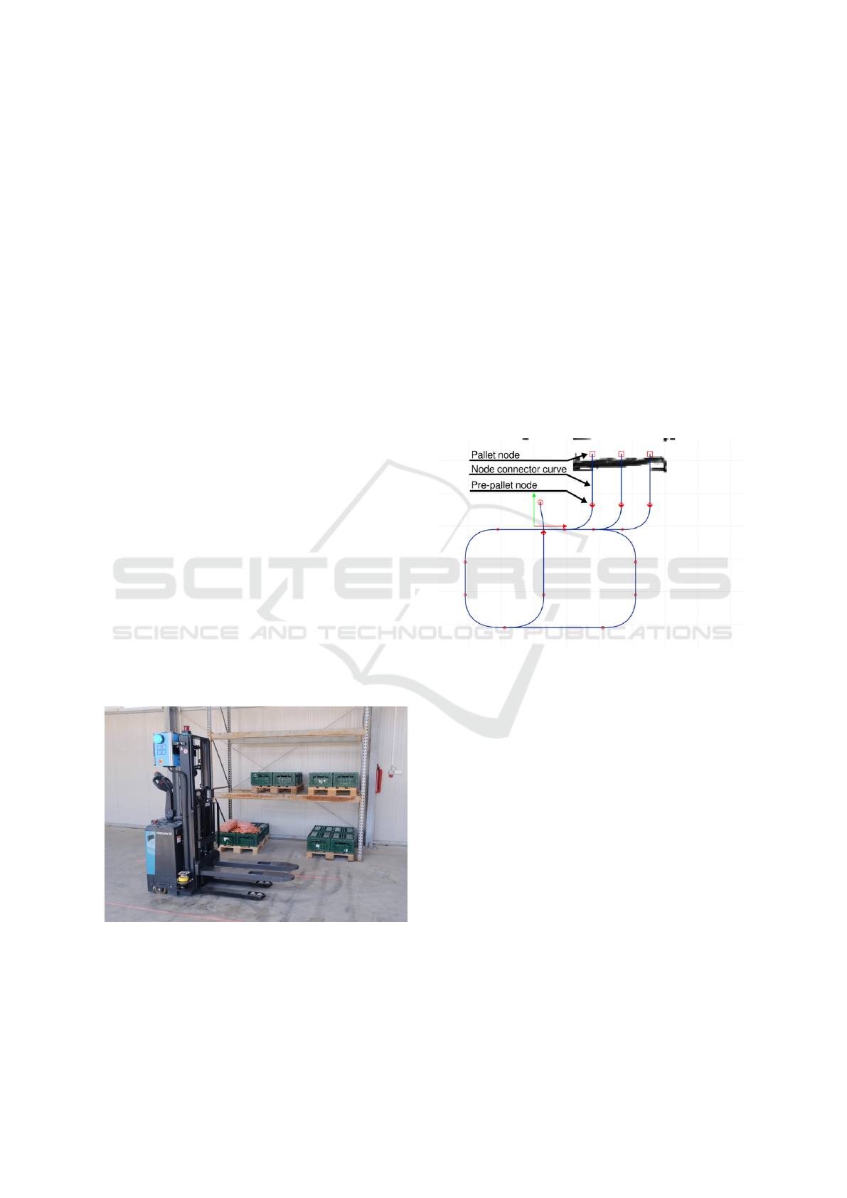
Figure 1: Robot used in the warehouse environment.
Therefore, the focus of this paper is an automated
forklift operating in a warehouse or comparable in-
dustrial environment, as shown in Figure 1. The fork-
lift is equipped with a 2D LiDAR sensor used for
global localization. Initially, the robot is manually
driven through the environment to create a static map
using a SLAM algorithm such as Cartographer (Hess
et al., 2016). This map is then used to localize the ve-
hicle during operation. The map origin can be used as
the global frame of reference (world frame).
In addition to localization features, the map also
includes a roadmap composed of nodes and connect-
ing curves. The nodes represent points of interest in
the environment, such as intersections, charging sta-
tions, pre-pallet positions, pallet positions, and sim-
ilar. The node connector curves define the paths the
forklift follows to navigate through the environment.
These elements of the roadmap are shown in Fig-
ure 2. Once a path is planned from one node to an-
other the forklift follows the path using a control algo-
rithm based on model predictive control (Kokot et al.,
2022).
Figure 2: Roadmap on the environment map.
Once the roadmap is generated on the map, the
robot is ready to execute missions. A mission con-
sists of one or more tasks, each defined by a task type,
a destination node, and relevant parameters, such as
the height of the pallet. A typical mission includes a
Pickup task followed by a Delivery task to transport a
pallet from one node to another.
As this work aims to address a problem that may
occur during a Pickup task, the execution steps of this
task are described in detail. A pickup task consists of
a pallet type destination node and includes parameters
such as the pallet height on a rack. Each pallet node
is connected to the roadmap through a correspond-
ing pre-pallet node with a straight line path. The pre-
pallet node serves as a staging point used to prepare
the forklift before entering the pallet node. For exam-
ple, if the pallet is located on a rack, the robot will
stop at the pre-pallet node and raise its forks to the
required height before proceeding.
The execution of a Pickup task follows this se-
quence of steps:
ICINCO 2025 - 22nd International Conference on Informatics in Control, Automation and Robotics
176

1. Navigate from the current pose to the pre-pallet
node.
2. Raise the forks to the specified pallet height.
3. Perform safety checks.
4. Enter the pallet node.
5. Raise the forks to lift the pallet.
6. Reverse back to the pre-pallet node.
To verify that the pallet is correctly aligned with
the node specified in the roadmap, the robot’s forktips
are equipped with proximity sensors. These sensors
are designed such that their laser beams must pass
through the pallet’s fork openings, confirming proper
alignment. This verification occurs during step 3 of
the Pickup sequence as part of the safety checks. If
the pallet has been placed manually by a human, mis-
alignment with the designated roadmap node is possi-
ble. In such cases, the robot will be unable to proceed
with the Pickup task.
To address this issue, an RGB-D camera is
mounted on the backplate of the robot, at the point
where the forks connect to the mast. The camera is
used to estimate the pallet’s pose on the map and ad-
just the pallet node accordingly. This modification re-
places steps 2 and 3 of the Pickup task with the fol-
lowing sequence of steps:
1. The camera calibration procedure computes the
coordinate transformation T
F C
from the forklift
frame F to the camera frame C and the corre-
sponding inverse transformation T
CF
. This trans-
formation depends on the camera’s mounting po-
sition, which may vary slightly during opera-
tion due to vehicle vibrations and motion-induced
shaking.
2. The forklift raises its forks to the specified pallet
height.
3. The pallet pose is estimated using the RGB-D
camera. The RGB image undergoes semantic seg-
mentation, and the segmented output, combined
with the corresponding depth image, is used to
calculate the pallet pose in the camera frame.
4. The pallet pose is transformed into the world
frame using the forklift’s pose, obtained from the
localization algorithm, and the transformations
T
F C
and T
CF
.
5. If the pallet is detected as misaligned, the vehi-
cle returns to the node immediately preceding the
current pre-pallet node. A new pre-pallet node is
calculated based on the estimated pallet pose in
the world frame, and the roadmap is temporarily
updated with a new pre-pallet and pallet nodes.
A new path is then planned and followed from
the current forklift position to this new pre-pallet
node.
These steps are repeated until the pallet is properly
aligned. The vehicle then proceeds with the Pickup
task.
3 METHOD DESCRIPTION
Sufficiently accurate camera pose calibration is a key
prerequisite for the successful execution of the pro-
posed pallet pickup procedure. In this section, we
outline the calibration method which is the main con-
tribution of this paper.
3.1 Point Cloud Semantic Segmentation
Our calibration method requires two point clouds:
one of drivable terrain (ground plane) and the other
containing both forks. To obtain these point clouds,
we have to perform semantic segmentation on the
RGB image and a geometrical analysis of the depth
image to obtain the point cloud. We can then merge
the two elements to obtain a semantically segmented
point cloud where each point has its’ assigned cate-
gory.
The semantic segmentation of an image is per-
formed using our proprietary deep learning model
based on (Or
ˇ
si
´
c and
ˇ
Segvi
´
c, 2021). The model assigns
each pixel a category chosen from: drivable, vertical,
other-object, other-forklift, other-vehicle, ego-forklift
(forks), cargo, pallet-empty, pallet-full and person.
The RGB image and corresponding semantically seg-
mented image are shown in Figure 3.
Geometrical analysis of the depth image is a stan-
dard procedure for obtaining a point cloud from the
depth image. It is trivial to calculate the x, y and z co-
ordinates of a point from the position of a pixel in the
RGB and depth images, the depth information, and
the internal parameters of the stereo camera.
Some stereo cameras, like the Realsense, have the
option to align the depth images to RGB images. Each
pixel in the depth image, and consequently each point
in the point cloud, corresponds to a pixel in the RGB
image. The merging process consists of coloring the
point cloud using the pixel colors of the semantically
segmented image. Figure 4 displays the point cloud
after the merging process.
3.2 Camera Pose Calibration
The camera calibration procedure outputs the pose of
the camera with respect to the vehicle, and the pose
Method for Automated Forklift Pallet Transfer with Simple Camera Calibration
177
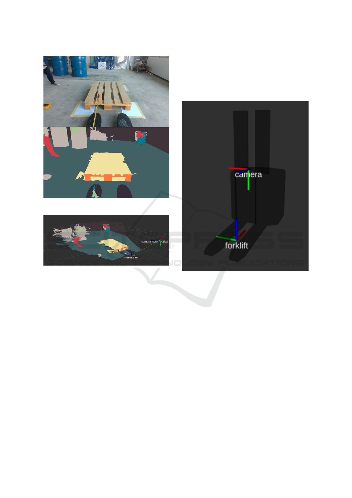
Figure 3: RGB and semantically segmented image.
Figure 4: Semantically segmented point cloud.
can be annotated as T
F C
. The F is the vehicle coor-
dinate frame (forklift), while C annotates the camera
coordinate frame.
A transform T
i j
is defined via its rotational and
translation matrices R
i j
and t
i j
where i, j are the tar-
get and source frames respectively
x
i
= T
i j
(x
j
) = R
i j
x
j
+ t
i j
(1)
where x
i
= [x y z]
T
contains the 3-D coordinates in the
i frame and x
j
contains the coordinates in the original
j coordinate frame.
To make the calculation of T
F C
easier, we can in-
troduce the coordinate frame C
′
:
T
F C
= T
F C
′
· T
C
′
C
(2)
where C
′
represents a coordinate system with the
same origin as the camera coordinate system, but
axis-aligned with the vehicle coordinate system F.
The coordinate frames F and C
′
are assigned as
depicted in Figure 5. The forklift frame F is a right-
handed coordinate frame where the origin is located
half-way between the two forks with the x-axis facing
forward, y-axis left, and z-axis facing up with respect
to the vehicle. Coordinate frame C is the optical frame
of the camera. The z-axis is facing away from the
camera lens, the x-axis is facing right and the y-axis
is facing down.
Figure 5: Simulated forklift with C
′
and F coordinate sys-
tems shown, where F is named forklift, while C
′
is named
camera.
3.2.1 Calculating the Camera Rotation
We set the translational part of T
C
′
C
as:
t
C
′
C
= [0 0 0]
T
(3)
and the rotational part as:
R
C
′
C
= X
ψ
Y
θ
Z
φ
(4)
where X
ψ
, Y
θ
and Z
φ
are elementary rotations around
the X, Y and Z axes of the C
′
coordinate frame. In this
way, we effectively separate the camera rotation and
the camera translation as two separate transforms to
make our calculation easier.
The camera yaw, defined by the angle φ, is set to
0 which can be achieved with sufficient accuracy by
mechanical means, e.g., by using a bubble level.
The camera roll, defined by angle ψ, is calculated
by calculating the angle between the negative y axis
of the camera y
c
= [0 − 1 0]
T
and the normal of the
ICINCO 2025 - 22nd International Conference on Informatics in Control, Automation and Robotics
178
ground plane⃗n
GP
. The normal of the ground is calcu-
lated using the RANSAC algorithm from the drivable
terrain (ground) point cloud, which is obtained as de-
scribed in Subsection 3.1.
The pitch of the camera, defined by the angle θ, is
calculated using characteristic image points; vanish-
ing point (VP) and the image center (IC), respectively.
θ = arctan
V P
x
− IC
x
f
x
(5)
where x is the x-coordinate measured in the camera
pixels for the V P and IC points and focal length f
expressed in pixels.
3.2.2 Calculating the Camera Translation
To calculate the translation vector T
F C
′
, we take ad-
vantage of the fact that the origin of the forklift frame
O
F
is visible from the camera and calculate T
C
′
F
in-
stead.
The rotational part of T
F C
′
is evident from Figure
5:
R
F C
′
= Z
π
2
Y
0
X
−
π
2
(6)
and the R
C
′
F
equals to:
R
C
′
F
= R
T
F C
′
(7)
The translation vector t
C
′
F
= [x
F
y
F
z
F
]
T
is calcu-
lated from the forks point cloud obtained as described
in Subsection 3.1. The point cloud must first be trans-
formed from C to the C
′
frame using the transform
calculated as described in Subsection 3.2.1.
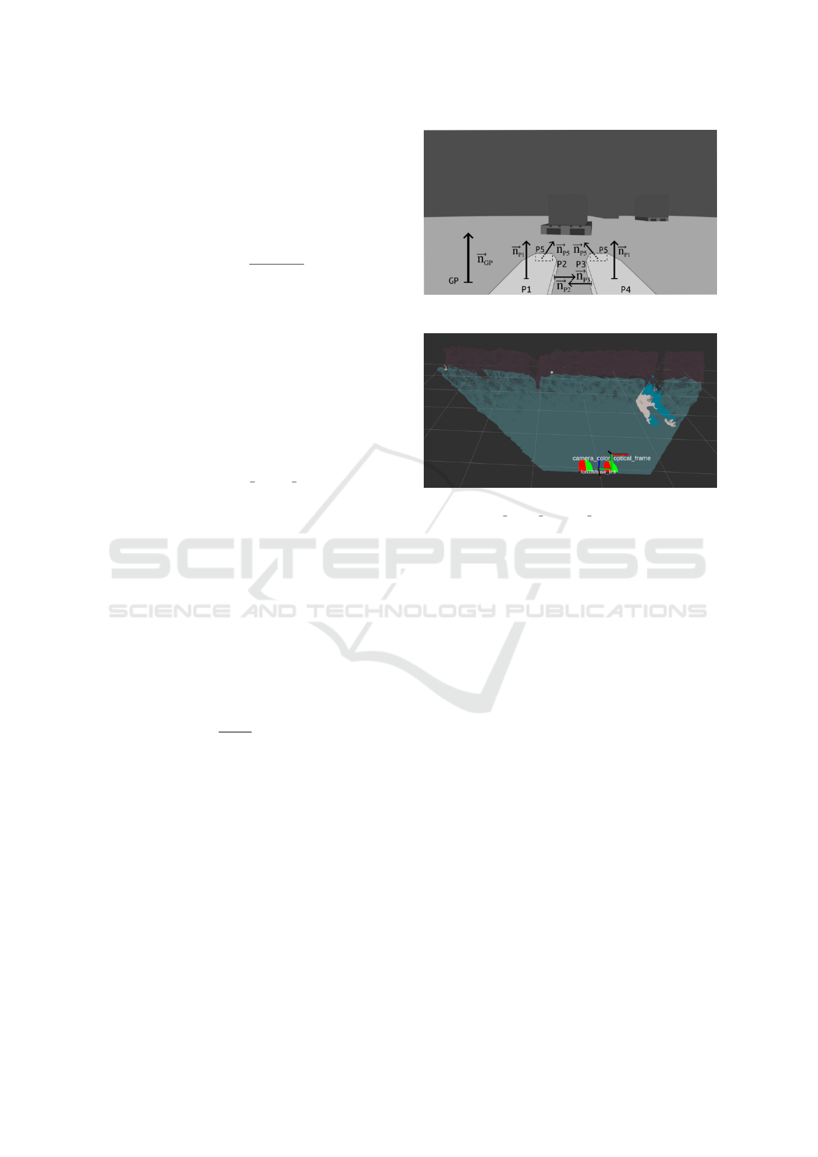
The calculation of x coordinate of the forklift
frame origin O
F
, uses the normal vectors⃗n
P2
and ⃗n
P3
of planes P
2
and P
3
which approximate the right side
of the left fork and the left side of the right fork re-
spectively, as depicted in Figure 6. The RANSAC al-
gorithm is used to extract the planes P
2
and P
3
.
x
F
=
|P
2
P
3
|
2
− |O
C
′
P
3
| (8)
where
|P
2
P
3
| = |O
C
′
P
2
| + |O
C
′
P
3
| (9)
is the distance between the P2 and P3 planes or the
distance between the insides of the forks. The O
C
′
=
[0 0 0]
T
is the origin of the C
′
frame.
The y coordinate is obtained by calculating the
distance of the O
C
′
from the ground plane G
p
.
y
F
= |O
C
′
G
p
| (10)
For this calculation, we are using the point-to-
plane distance formula.
The z coordinate is obtained by calculating the
⃗n
P5
, normal of the plane P
5
which captures the fork
tips oriented to the pallet.
⃗n
P5
=⃗n
GP
×⃗n
P2
(11)
Figure 6: Planes and normals used in the calculation.
Figure 7: Calibrated camera position. The frame C is anno-
tated as camera color optical frame.
The fork tips are the points with the maximum
value of z coordinate in the point cloud that represents
the fork points.
z
F
= |O
C
′
P
5
| − OFFS
z
(12)
where OFFS
z
is the offset between O
F
and the end of
the forks. Finally, the translation vector t
F C
′
of T
F C
′
is equal to:
t
F C
′
= −R
F C
′
· t
C
′
F
(13)
4 EXPERIMENTS AND RESULTS
The method is evaluated in a simulated environment
and on a real forklift in a simple industrial environ-
ment. Simulation offers an opportunity to experi-
ment with a wider range of camera angles with known
ground truth. Experiments on real hardware provide
insight into real-world applicability of the method.
The tolerance for roll and pitch we deem appropriate
is 1 degree. For the x, y and z coordinates, we allow
up to 10 mm of error. These tolerance still allow us to
pick up the pallet safely.
4.1 Simulation Evaluation
In simulation, the pose of the camera with respect to
the vehicle T
F C
can be easily configured via param-
eters set through YAML files. We created a Python
Method for Automated Forklift Pallet Transfer with Simple Camera Calibration
179
script which generated a list of transforms T
F C
we
wanted to test, ran the calibration procedure in the
simulation for each transform and then stored the re-
sults in a CSV file. Lastly, we compared the calibra-
tion output with the transform specified in the YAML
file.
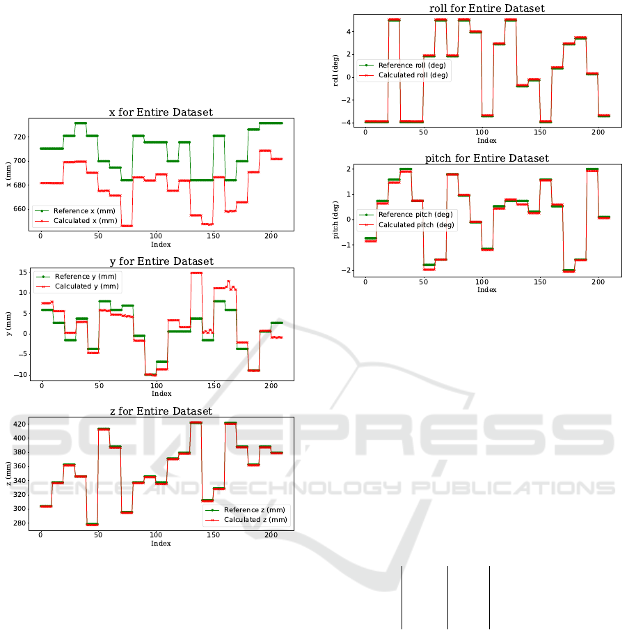
Figure 8: Results for t
FC
calibration (simulation).
Figure 8 shows that the y and z coordinates have
been calibrated according to specification (error <=
10mm). There is a static offset of x-coordinate cali-
bration of approximately 3 cm. The reason could be
that the fork tips are not a strong enough feature even
in a simulation environment. Figure 9 shows that roll,
pitch and yaw have been calibrated according to spec-
ification (error <= 1 deg).
4.2 Real Data Evaluation
To test our method, we used a retrofitted autonomous
forklift based on the Baoli ES15 platform with a cam-
era rig mounted on the back, depicted in Figure 1.1.
The camera rig consists of a mounting plate for the
Intel Realsense D435i camera and a Jetson Orin AGX
DevKit (32 GB), powered by a 21 Ah power bank.
Figure 9: Results for rotation R
C
′
C
calibration (simulation).
The camera was attached to the camera rig via ex-
changable camera mounts. The camera mounts were
designed and 3D printed with different combinations
of roll and pitch. The camera yaw was always kept
at 0, which was insured by using a bubble level. It is
important to note that all rolls were higher than 23 de-
grees, to ensure that the fork tips are always within the
camera field of view. Figure 10 displays the close-up
of the camera rig used during the experiments. Ta-
ble 1 contains all the pitch and roll combinations we
tested and their corresponding data indices in the re-
sult plots.
Table 1: Available camera mount configurations.
id ψ (°) φ (°) data indicies
1 -23 0 0 - 9
2 -24.5 -1 10 - 19
3 -25 0.5 20 - 29
For the evaluation on real data, we attached the
camera rig to our forklift, ran the calibration proce-
dure and stored the data used and the result calculated
in a ROS bag. For each camera mount, we collected
10 samples to see if the calibration is consistent be-
tween different runs.
Figure 11 shows that the z coordinate is the most
accurately calibrated coordinate. The reason could be
that the ground plane segmented from the RGB and
depth images is large and the normal calculation is ac-
curate. There exists a static offset for the x-coordinate
of 20 mm which is still acceptable for us. We think
this is caused by the lack of features on the fork tips.
The y-coordinate displays a difference of up to 20 mm
ICINCO 2025 - 22nd International Conference on Informatics in Control, Automation and Robotics
180
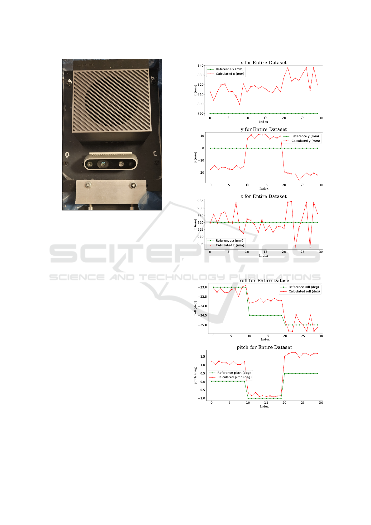
Figure 10: Camera rig used for experiments.
in one case. The camera was unmounted and mounted
between experiments, which could be the reason for
the large deviation in the y-coordinate. Deviations of
≤ 10 mm are acceptable for us and still allow a suc-
cessful pallet pick-up.
Figure 12 shows that the camera roll and pitch
have been calibrated correctly. Our experiments have
shown that the fork top planes and the ground plane
are good features, whereas the fork side and fork tip
planes are not. We should consider options to make
x, y and roll calibration more reliable.
With this setup and calibration, we were able to
successfully conduct pick-up operations with our au-
tomated forklift. Since the y-coordinate calibration
wasn’t as reliable as we expected, we had to add a 20
mm offset to the automatically calibrated value. All
the other camera mounting values were used without
modifications.
5 CONCLUSIONS
In this paper, we have described a practical method
for calibrating the camera pose for accurate and adap-
tive pallet pickup tasks by automated forklifts. The
method relies on RGB-D camera data and combines
semantic segmentation of RGB data with geometric
computations on the depth image channel. It lever-
ages the known geometry of the forks to compute the
transformation matrix between the vehicle frame of
reference (attached to the controlled point of the vehi-
Figure 11: Results for t
FC
calibration.
Figure 12: Results for rotation R
C
′
C
calibration.
cle) and the camera frame of reference. The computed
transformation matrix plays a key role in enabling the
vehicle to accurately drive into the pallet and pick it
Method for Automated Forklift Pallet Transfer with Simple Camera Calibration
181

up. This ability is important in human-robot collabo-
rative workflows, where robots need to pick up pallets
which have been inaccurately placed by human oper-
ators.
To validate the method, we have performed exper-
iments in a simulated environment and on a real au-
tomated forklift in a simple industrial setting. The re-
sults indicate that the method can estimate the actual
camera pose with sufficient accuracy in most cases.
Some robustness issues have been identified, related
to smaller fork features which suffer from noisy esti-
mates. Overall, we were able to demonstrate success-
ful pickups of misplaced pallets in a simple industrial
environment.
In future work, we will focus on improving the ro-
bustness of the method and validating it in diverse in-
dustrial settings, with different pallet and load types.
Furthermore, we will look to extend the approach to
other types of operations, such as estimating available
space for pallet delivery on storage racks and in block
storage.
PATENT NOTICE
This paper is derived from the European patent appli-
cation EP24223684.2 named Method for automated
forklift transfer with simple camera calibration filed
with the European Patent Office.
ACKNOWLEDGEMENTS
The authors thank the late professor Sini
ˇ
sa
ˇ
Segvi
´
c and
his lab members at the University of Zagreb, Faculty
of Electrical Engineering and Computing Zagreb for
their continued collaboration in our R&D projects and
valuable insight into various topics regarding com-
puter vision and machine learning. The authors also
thank their partner company VAR d.o.o. for providing
the forklift platform and access to the testing area, as
well as the company 3DTech for their help in building
the testing camera rig.
This work is financed by the EU -
NextGenerationEU, through grant number
NPOO.C3.2.R2/I1.04.0020 ”Collaborative map
building and traffic control in logistics KolIKUL”.
The views and opinions expressed are those of the
author(s) only and do not necessarily reflect those of
the European Union or the European Commission.
Neither the European Union nor the European
Commission can be held responsible for them.
REFERENCES
Hess, W., Kohler, D., Rapp, H., and Andor, D. (2016). Real-
time loop closure in 2d lidar slam. In 2016 IEEE In-
ternational Conference on Robotics and Automation
(ICRA), pages 1271–1278.
Kim, M. and Byun, S. (2009). Mono vision based pal-
let position and posture measurement method. https:
//patents.google.com/patent/KR101095579B1. Ex-
pired.
Kokot, M., Mikli
´
c, D., and Petrovi
´
c, T. (2022). A uni-
fied mpc design approach for agv path following. In
2022 IEEE/RSJ International Conference on Intelli-
gent Robots and Systems (IROS), pages 4789–4796.
Libing, Q., Jinbao, X., Yong, W., Jihai, L., Lisong, H.,
Huan, Z., Lin, C., and Hao, H. (2024). A deep vi-
sion recognition and positioning method for agv ter-
minal operations. https://patents.google.com/patent/
CN118644532A. Pending.
Or
ˇ
si
´
c, M. and
ˇ
Segvi
´
c, S. (2021). Efficient semantic seg-
mentation with pyramidal fusion. Pattern Recogni-
tion, 110:107611.
Qinyuan, R., Jiangnan, P., and Chuang, L. (2023). Tray
detection and positioning method and system for un-
manned forklift application. https://patents.google.
com/patent/CN116309882A. Pending.
Ulbrich, S., de Bley, A., Wolf, E., Fischer, B., Martin, C.,
Trabert, J., Syleiman, A., and Sternitzke, C. (2020).
Autonomous industrial truck. https://patents.google.
com/patent/EP4239430A1. Pending.
Vu, V.-D., Hoang, D.-D., Tan, P., Nguyen, V.-T., Nguyen,
U., Hoang, N.-A., Phan, K.-T., Tran, D.-T., Vu, D.-Q.,
Ngo, P.-Q., Duong, Q.-T., Nhat, N., and Hoang, D.-
C. (2024). Occlusion-robust pallet pose estimation for
warehouse automation. IEEE Access, PP:1–1.
Xiao, J., Lu, H., Zhang, L., and Zhang, J. (2017). Pallet
recognition and localization using an rgb-d camera.
International Journal of Advanced Robotic Systems,
14:172988141773779.
Zhao, J., Li, B., Wei, X., Lu, H., L
¨
u, E., and Zhou, X.
(2022). Recognition and location algorithm for pallets
in warehouses using rgb-d sensor. Applied Sciences,
12(20).
ICINCO 2025 - 22nd International Conference on Informatics in Control, Automation and Robotics
182
