
A Web-Controlled, Modular 3D-Printed Exoskeleton for Upper Limb
Stroke Recovery
Crina B
˘
arbieru
a
and Isabela Dr
˘
amnesc
b
Department of Computer Science, West University of Timis¸oara, Romania
Keywords:
Robotic Hand Exoskeleton, Stroke Rehabilitation, 3D-Printed Exoskeleton, Remote Monitoring, Web-Based
Rehabilitation Platform.
Abstract:
Stroke survivors often experience partial or complete loss of hand function, significantly affecting their ability
to perform everyday tasks. Current rehabilitation methods can be resource intensive and require significant
human intervention. This paper aims to develop a portable, modular, 3D-printed robotic hand exoskeleton that
provides targeted repetitive exercises designed to enhance motor recovery. This exoskeleton is controlled via
a web application, which includes progress-tracking functionalities for both patients and physical therapists,
enabling remote monitoring. Preliminary testing was conducted with one patient to evaluate the usability
and efficacy of the device. Feedback was collected from a physical therapist to assess the feasibility of the
exoskeleton. The proposed system offers a scalable, cost-effective solution for post-stroke hand rehabilitation.
Further studies with larger cohorts are needed to validate efficacy.
1 INTRODUCTION
Stroke is one of the leading global causes of death
and long-term disability, with nearly 12 million new
cases every year (Feigin et al., 2025). Approxi-
mately 25.3% of patients develop post-stroke spas-
ticity (Zeng et al., 2021), a condition in which mus-
cle stiffness and abnormal muscle contractions affect
movement, limiting their ability to perform daily tasks
and regain independence.
The development of innovative therapeutic tools,
such as robotic exoskeletons, holds promise for im-
proving the rehabilitation process, particularly for
those with limited mobility due to spasticity. Some
studies found robot-assisted therapy in acute and sub-
acute stroke patients more effective than traditional
therapy (Masiero et al., 2007; Sale et al., 2014; Taka-
hashi et al., 2016), although others found no signif-
icant differences between the two approaches if ex-
ercises were performed at a similar intensity (Kahn
et al., 2006; Hesse et al., 2014).
In the last three decades, a wide range of upper-
limb robotic exoskeletons have been developed for
patients to perform independent and repeatable exer-
cises remotely, allowing for a more personalized ap-
a
https://orcid.org/0009-0004-1794-6510
b
https://orcid.org/0000-0003-4686-2864
proach to rehabilitation. However, many existing sys-
tems rely on minimal control interfaces, with little ca-
pability for progress tracking or therapist supervision.
The aim of this paper is to address some of the gaps in
existing solutions and design a portable, 3D-printed,
modular exoskeleton controlled via a web application,
enhancing the patient’s rehabilitation experience and
streamlining the progress supervision process.
2 RELATED WORK
Finding a balance between design simplicity and
portability constitutes a significant challenge when
designing a robotic hand exoskeleton. We can dis-
tinguish a category of exoskeletons that actuate the
fingers via cable systems placed on the palmar side
of the hand. While it is relatively straightforward,
this approach can prevent patients from fully sensing
and grasping objects during rehabilitation exercises.
The device described in (Selvaraj Mercyshalinie et al.,
2023) uses fishing lines attached to distal inter-
phalangeal (DIP) joint hooks and guided through
metacarpophalangeal (MCP) joint hooks. The mod-
ular exoskeleton developed by (Chirinos and Vela,
2021) assists with the flexion and extension of the
thumb, index, and middle fingers using a pulley con-
nected to a direct current (DC) motor. Teflon tubes
150
B
ˇ
arbieru, C. and Dr
ˇ
amnesc, I.
A Web-Controlled, Modular 3D-Printed Exoskeleton for Upper Limb Stroke Recovery.
DOI: 10.5220/0013835400003982
Paper published under CC license (CC BY-NC-ND 4.0)
In Proceedings of the 22nd International Conference on Informatics in Control, Automation and Robotics (ICINCO 2025) - Volume 2, pages 150-157
ISBN: 978-989-758-770-2; ISSN: 2184-2809
Proceedings Copyright © 2025 by SCITEPRESS – Science and Technology Publications, Lda.

guiding the wires allow for better object-grasping ca-
pabilities, although they still remain limited.
This issue can be solved by placing cables on the
sides of the fingers, as can be observed in (Chiri et al.,
2009). Extension is actively achieved via Bowden ca-
bles pulled by a slider connected to the DC motor.
DC motors are commonly used in robotic applica-
tions due to their precise control and compact size.
Their rotational torque can be adapted to simulate the
movement generated by a linear actuator, which is the
mechanism leveraged by (Chiri et al., 2009). Flexion
is achieved passively, with cables attached to linear
compression springs.
Some of the existing solutions flex the fingers by
pushing rather than pulling them, allowing the pal-
mar side of the hand to remain free. The portability
of devices in this category is influenced by the choice
of hardware components. In (Wang et al., 2020) the
palm is positioned in an upward position and braces
support it to prevent fatigue. The system flexes one
finger at a time via pneumatic muscles attached to
plates and wheels of different radii. This setup sig-
nificantly limits the range of rehabilitation exercises
which can be performed. (Ho et al., 2011) uses a
linear actuator and a dual arch guide mechanism to
actuate the MCP and proximal interphalangeal (PIP)
joints. Electromyography (EMG) sensors are inte-
grated to detect movement intent and a wireless con-
trol unit allows the therapist to choose from different
training modes. The exoskeleton described in (San-
dison et al., 2020) achieves a 90
◦
range of motion
(ROM) at the MP and 100
◦
at the PIP. The elastic dis-
tal segment is user dependent and can be avoided to
achieve tactile sensation when grasping objects.
The integration of 3D-printing technology in
robotic exoskeletons has enabled more innovative,
customizable designs and has lead to the development
of new actuation mechanisms. (Yap et al., 2015) uses
3D-printed molds to create accordion-like, elastomer
actuators. Actuators in (Ridremont et al., 2024) are
pressurized to flex the joints and vacuumed to extend
them, while those in (Yap et al., 2017) use the oppo-
site mechanism. Other devices (Fiorilla et al., 2009;
Sandison et al., 2020; Selvaraj Mercyshalinie et al.,
2023) use 3D-printed parts as components of the ex-
oskeleton to lower the cost, reduce the weight, and
more easily adapt the exoskeleton to diverse patient
needs.
Although most robotic exoskeletons are con-
trolled via hardware components, some implement
mobile or Web applications to personalize rehabil-
itation sessions and improve user experience. In
(Fiorilla et al., 2009), the application developed
in Microsoft Visual C++ and National Instruments
LabView
TM
communicates with the robot’s con-
troller, reads the input from sensors and encoders to
reconstruct the MCP angle and monitors the device
during rehabilitation exercises. The Android mobile
application in (Selvaraj Mercyshalinie et al., 2023)
contains buttons for each individual finger. Flexion
is done gradually, in three stages, and the fingers are
relaxed by pressing dedicated buttons.
3 EXOSKELETON DESIGN
The proposed solution utilizes the advantages of 3D-
printed components to design a modular robotic ex-
oskeleton. The current system is comprised of a
single-finger module, with the possibility to connect
multiple such modules to achieve a full-hand ex-
oskeleton.
3.1 Hardware Components
The robotic exoskeleton is controlled by an Arduino
Nano ESP32 board, chosen for its integrated Wi-Fi,
enabling communication with the web-based client
interface. Thus, users are able to remotely select ex-
ercise modes and intensity.
Figure 1 illustrates the wiring configuration of the
exoskeleton’s electronic components. The MG90S
servomotor interfaces with the Arduino via the D9
digital pin, utilizing Pulse Width Modulation (PWM)
for precise control.
Figure 1: Circuit Diagram of the System.
Due to the Arduino Nano ESP32’s 3.3V logic
level, the 5V servomotor cannot be directly powered
by the board. Instead, an external power source is
employed, consisting of a power bank module. This
module supplies 5V at 2A, sufficient to drive multiple
servomotors if needed. To ensure a common refer-
ence voltage, the grounds of the Arduino, servomotor,
and power bank are interconnected.
The flex sensor input is measured using a volt-
age divider circuit, a configuration which reduces the
A Web-Controlled, Modular 3D-Printed Exoskeleton for Upper Limb Stroke Recovery
151
voltage to a lower value while maintaining constant
current flowing through the resistors. In this setup,
the input voltage spans the entire resistor network.
The output voltage is measured from the junction be-
tween two resistors, with its magnitude dictated by
their resistance ratio. The flex sensor has a nominal
resistance of 10KΩ(±30%), and when paired with
a 26.8KΩ fixed resistor, the resulting voltage divi-
sion ensures analog readings remain below the mid-
point of the Arduino’s 12-bit analog to digital con-
verter (ADC) range (2047). The sensor is powered
directly from the Arduino’s 3.3V pin, which serves as
the voltage divider’s supply source, ensuring compat-
ibility with the board’s analog input range.
3.2 3D-Printed Components
The components of the exoskeleton are designed us-
ing Autodesk Tinkercad (Autodesk Inc., 2025), a
web-based computer-aided design (CAD) platform
that simplifies 3D modeling through an intuitive,
primitive-based approach. CraftWare Pro is used to
slice the components with fine layer resolution, which
are then printed using the Craftbot Flow 3D printer.
The distal and metacarpal components use a thermo-
plastic polyurethane (TPU) 95A filament. This semi-
flexible, rubber-like material allows the exoskeleton
to fit more comfortably on different finger sizes. The
other components, involved in the actuation mecha-
nism, are printed using a polylactic acid (PLA) fila-
ment. This material is selected for its strength, as it
needs to withstand repeated mechanical stress.
The fingertip interface (Figure 2a) positioned on
the distal phalanx, supports the attachment of two
guide rods, which are designed to follow an arched
channel. The metacarpal component (Figure 2b) pro-
vides structural support and serves as the mounting
point for the arched component. Two tubular exten-
sions on either side of mounting channel guide the
wires used by the actuation mechanism.
(a) Distal Element. (b) Metacarpal Element.
Figure 2: 3D Models of Exoskeleton Components.
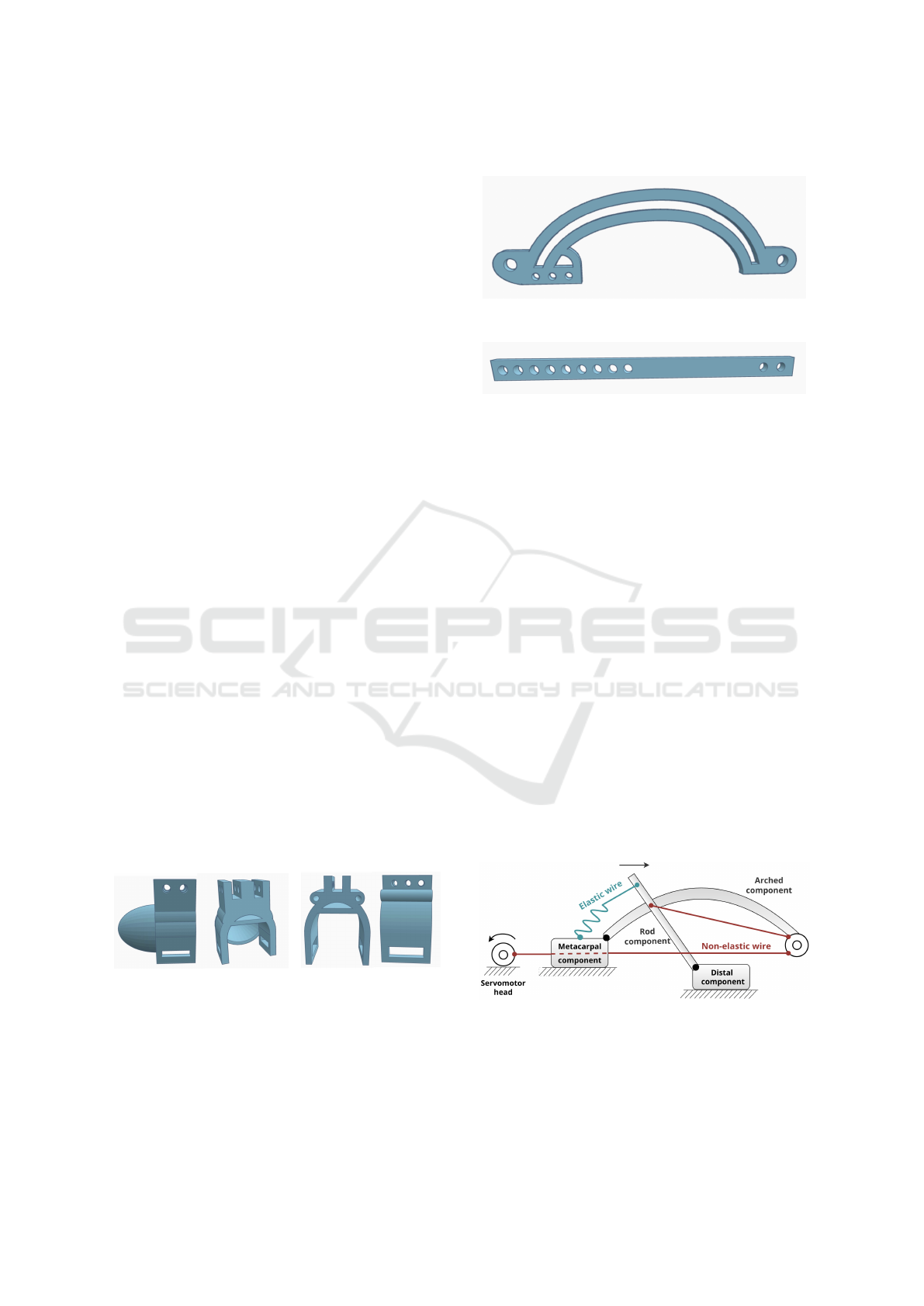
The arched component (Figure 3) guides the rod-
shaped components (Figure 4) placed laterally, which
slide and convert the curved trajectory into a con-
trolled flexion movement. This movement simulta-
neously bends the DIP and PIP joints, mimicking the
natural movement of a finger.
Figure 3: 3D Model of Arched Component.
Figure 4: 3D Model of Rod-Shaped Component.
3.3 Actuation Mechanism
Actuation is achieved via a system of wires attached
to a servomotor. A non-elastic wire is attached to
the rod-shaped components, passes through the guide
components mounted distally on the arch compo-
nent and then through the guides integrated into the
metacarpal component before terminating at the ser-
vomotor head.
During flexion, the servomotor’s torque is trans-
formed into the linear movement of the rods along
the arched trajectory, as shown in Figure 5. Due to
pulley-like elements guiding the non-elastic wire at
the distal end of the arched component, the rotational
movement of the servomotor head leads to a transla-
tional movement of the rods along the arched trajec-
tory. The finger extension mechanism is achieved pas-
sively, through an elastic wire positioned between the
proximal end of the arched element and the extremi-
ties of the rods. While the servomotor releases tension
on the wires, the elastic wire provides the force nec-
essary to pull back the rods and bring them into their
initial position.
Figure 5: Kinematic Diagram of the System.
Figures 6a and 6b showcase the position of the fin-
ger when the exoskeleton assists with extension, and
flexion respectively.
ICINCO 2025 - 22nd International Conference on Informatics in Control, Automation and Robotics
152
(a) Exoskeleton-Assisted Extension.
(b) Exoskeleton-Assisted Flexion.
Figure 6: Finger Position During Exoskeleton-Assisted Ex-
ercises.
3.4 Sensors
The distal and metacarpal components of the ex-
oskeleton have slots designed to accommodate the
movement of the flex sensor during finger flexion and
extension. The sensor is secured at the metacarpal
component and passes freely through the fingertip’s
slot. This allows it to slide slightly as the distance
between the two components increases when the fin-
ger is bent and decreases when the finger is fully ex-
tended.
When measuring the movement of the finger, the
system first establishes a baseline reading with the fin-
ger fully extended. In this situation, the resistance of
the flex sensor is minimum, while the voltage reaches
its maximum value. During flexion, the resistance of
the flex sensor increases, causing a proportional volt-
age drop. The system thus captures the combined
bend of the DIP and PIP joints by tracking the voltage
change.
4 SOFTWARE DESIGN
The robotic hand exoskeleton is controlled via a web
application, which communicates with the robot us-
ing the controller’s Wi-Fi module. The web applica-
tion serves two distinct user roles: patients and super-
visors. An intuitive and responsive interface improves
the patient’s experience, which not only serves as the
control interface for the exoskeleton, but as a tool
for recording exercise sessions and tracking progress.
Furthermore, physical therapists are able to monitor
the activity of their patients, essential for the safety
and efficacy of remote rehabilitation.
The Client Layer is built with React, serving as the
user interface patients and supervisors interact with.
The Application Layer is a Spring Boot application,
enforcing role-based access via Spring Security. Ad-
ditionally, sensitive information, such as user pass-
words, is encrypted through BCrypt hashing. For per-
sistent data storage, the system employs MySQL as
its relational database management system. The re-
lational model is suitable for the structured nature of
the application’s data, including user accounts and in-
formation related to exercise sessions.
The patient Graphical User Interface (GUI) pro-
vides a control interface in the Active Exercises screen
(Figure 7a), where they are able to select the level of
intensity on a 1-10 scale and perform exoskeleton-
assisted, repeated movements. Level 1 represent a
slight movement of the exoskeleton, and corresponds
to a 18
◦
rotation of the servomotor head, while level
10 ensures full exoskeleton movement and a 180
◦
ser-
vomotor head rotation. In Passive Mode (Figure 7b),
the patient attempts independent flexion and the appli-
cation screen displays the flex sensor input as a per-
centage of the total range of movement of the DIP and
PIP joints. All robot-assisted or passive sessions are
recorded automatically and displayed in the Patient
Progress component (Figure 7c). Patients view statis-
tics related to their rehabilitation journey, such as the
number of assisted exercise sessions completed in the
current week, and a calendar containing both assisted
and passive sessions.
Supervisors have a similar view over their pa-
tients’ progress in the Supervisor Progress screen
(Figure 7d), where the same data is aggregated and
shown in the form of patient progress cards. The
progress cards contain metrics about the patients med-
ical information, such as: the number of days since
the stroke occurred, the number of days in rehabili-
tation, and exercise sessions, like the number of ses-
sions in the current week and average session dura-
tion. Furthermore, for better data visualization, the
cards contain a similar calendar to that of the patients,
but with exercise sessions and passive mode data sum-
marized.
A Web-Controlled, Modular 3D-Printed Exoskeleton for Upper Limb Stroke Recovery
153
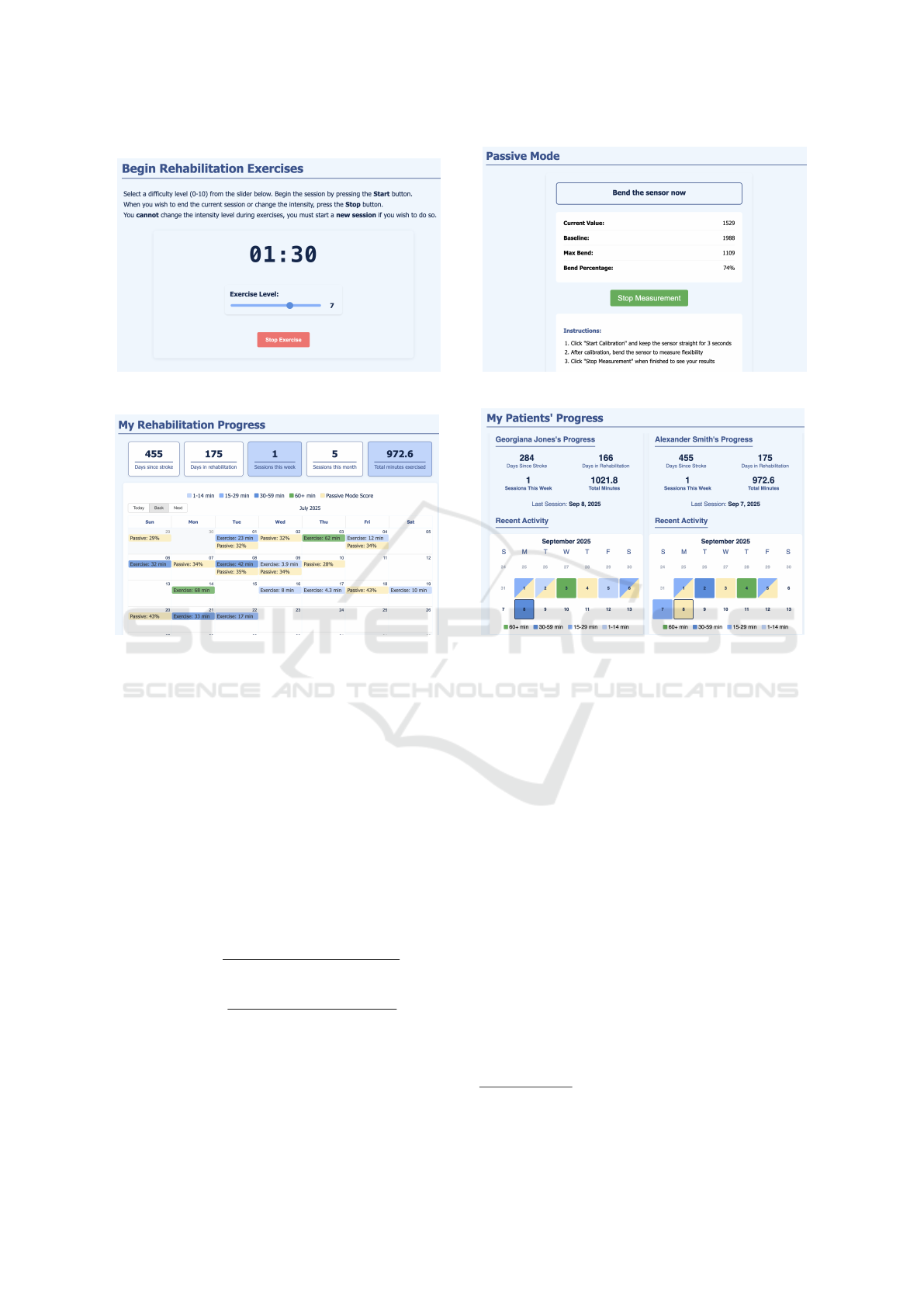
(a) Active Exercises Screen. (b) Passive Mode Screen.
(c) Patient Progress Screen. (d) Supervisor Progress Screen.
Figure 7: GUI Screens of the Web Application.
5 EXPERIMENTS AND RESULTS
The finger joint angles were analyzed using a custom
Python script that combines computer vision track-
ing with geometric angle calculations. The OpenCV
library is used to load a side-view recording captur-
ing one full flexion movement of the exoskeleton.
Three joint locations (MCP, PIP, DIP) and an addi-
tional point representing the finger tip (TIP) are man-
ually selected on the first video frame. This is used for
joint angle calculation, by applying the scalar product
formula:
θ
PIP
= cos
−1
(PIP − MCP)· (DIP − PIP)
|PIP − MCP| · |DIP − PIP|
(1)
θ
DIP
= cos
−1
(DIP − PIP) · (TIP − DIP)
|DIP − PIP| · |TIP − DIP|
(2)
Initially, we attempted to automate joint detection
and angle computation entirely through the CSRT al-
gorithm (Channel and Spatial Reliability Tracking)
OpenCV. However, due to interference from the ex-
oskeleton’s distal component, the TIP point could not
be accurately identified, leading to incorrect DIP an-
gle calculations (Figure 8a). To resolve this, we modi-
fied the program to allow periodic manual corrections,
allowing us to reselect joint positions at fixed inter-
vals. We tested three different scenarios, manually
positioning the MCP, PIP, DIP and TIP points every
5, 8, and 10 frames respectively, to balance tracking
accuracy with manual intervention.
The results revealed that the PIP joint reached
a maximum angle of 110–115 degrees, correspond-
ing to a flexion of 65–70 degrees from full exten-
sion. The DIP joint reached a peak flexion of approx-
imately 65 degrees, although this decreased slightly
to around 60 degrees towards the end of the move-
ment. To ensure robustness, we applied a smoothing
filter (3-frame moving average) to the raw angle data,
thus filtering out noise and tracking errors between
manual corrections. To contextualize our results, we
consulted a physical therapist
1
with experience in the
field of hand rehabilitation. We learned that similar
1
The physical therapist consented to the use of their
feedback in this paper.
ICINCO 2025 - 22nd International Conference on Informatics in Control, Automation and Robotics
154
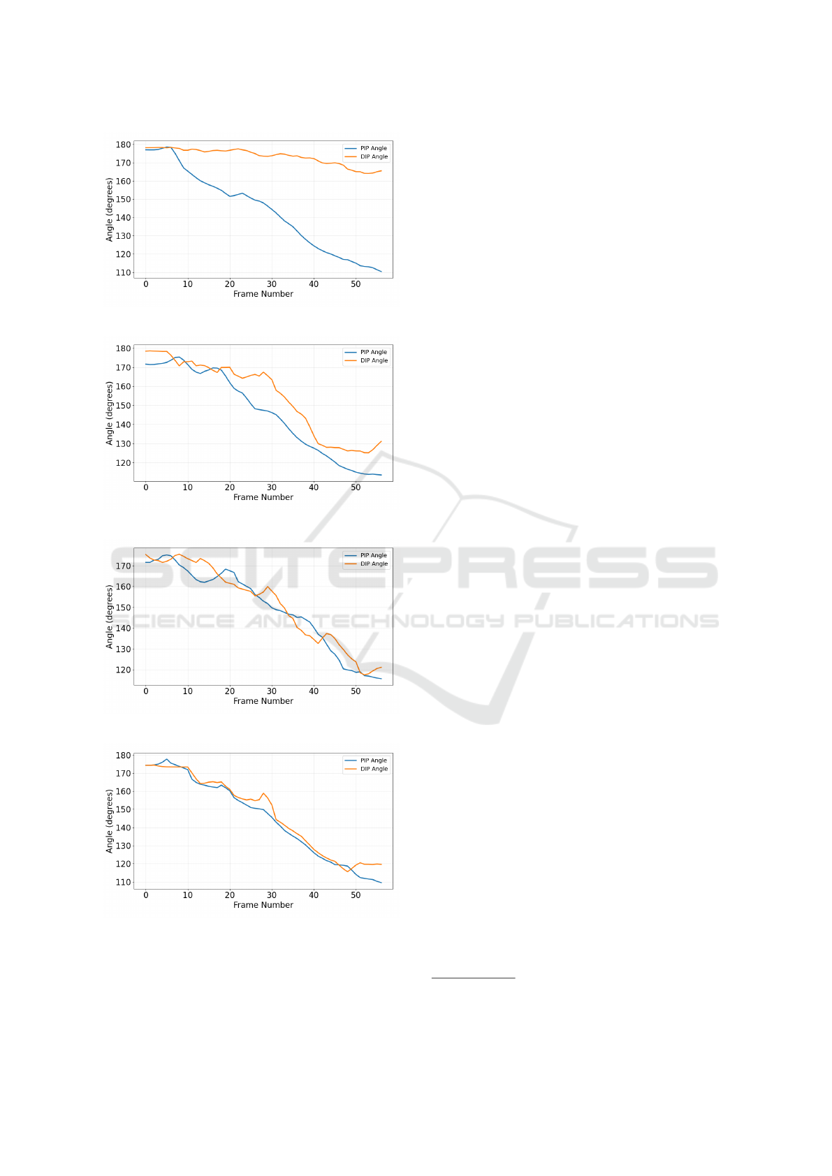
(a) Automatic Detection.
(b) 5-frame Correction.
(c) 8-frame Correction.
(d) 10-frame Correction.
Figure 8: Experiment Results: PIP and DIP Angles During
Exoskeleton-Assisted Flexion.
robotic technologies, particularly pneumatic-actuated
gloves, tend to lose precision after 3–4 weeks as mate-
rials stretch and deform, limiting their clinical utility.
While our 3D-printed PLA exoskeleton takes a dif-
ferent approach, similar wear-and-tear issues might
eventually emerge with prolonged use. Since PLA
isn’t commonly used in clinical exoskeletons, or its
use is limited and does not constitute a significant pro-
portion of exoskeleton components, durability studies
should be conducted to evaluate the performance of
this material.
We conducted additional experiments to measure
the load on the elastic component of the exoskeleton,
which not only assists in passive extension, but in-
fluences the flexion mechanism as an opposing force
to the one generated by the torque of the servomo-
tor. In this scenario, the chosen elastic component
was latex wire with a diameter of 1 millimeter and
≈ 700% elasticity. The exoskeleton was tested with a
dynamometer to record applied forces. We measured
that a force of about 0.8N was required to stretch the
wire efficiently to enable full exoskeleton movement.
The MG90S servomotor has a 1.8kg/cm stall torque
at 4.8V . The non-elastic wire is fixed at 4cm from
the servomotor shaft, therefore a maximum force of
≈ 4.4N can be applied before the servomotor stalls, in
ideal conditions. Additional factors such as resistance
from the elastic wire and the finger, friction between
exoskeleton components and voltage drops could pro-
vide an explanation for the need of patient interven-
tion when performing exoskeleton-assisted rehabili-
tation exercises, as the servomotor is not able to gen-
erate enough force for passive finger flexion. This is
beneficial in situations where patient intervention is
required during rehabilitation exercises, and the de-
gree of intervention can be increased by choosing a
thicker, less elastic wire.
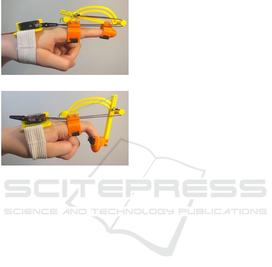
Furthermore, we conducted preliminary testing
with a patient
2
(Figure 9), who reported that the de-
vice was comfortable and lightweight.
Although we originally designed and tested the
device for the index finger, the patient required reha-
bilitation for the little and ring fingers. This demon-
strates an advantage of the modular exoskeleton, as
it can be adapted and reused based on patient needs.
During assisted flexion trials, the exoskeleton demon-
strated measurable improvement, although the ROM
was constrained by the patient’s capability to initiate
movement. The device augmented flexion by a small
but consistent margin beyond the patient’s indepen-
dent effort, suggesting its potential as a training aid
for motor recovery.
2
The patient consented to the use of their feedback and
photo in this paper.
A Web-Controlled, Modular 3D-Printed Exoskeleton for Upper Limb Stroke Recovery
155

Figure 9: Patient During Preliminary Testing.
A demonstration video showcasing the main fea-
tures of our developed system can be accessed at
https://youtu.be/LA84F36UVH4.
6 CONCLUSIONS AND FUTURE
WORK
The developed system successfully integrates a 3D-
printed finger exoskeleton with a web-based control
interface. Similarly to (Chiri et al., 2009), it is a mod-
ular exoskeleton that uses active and passive mecha-
nisms to flex and extend the fingers, though inverted
(passive flexion and active extension). Where their
design uses a system of 6 pulleys, 2 for each joint,
the device described in this paper achieves simulta-
neous DIP and PIP flexion and extension via a set of
servomotor-driven cables. This improvement reduces
mechanical complexity while maintaining a compara-
ble range of motion.
The arched trajectory mechanism is similar to that
developed by (Ho et al., 2011), but with some opti-
mization. The linear actuators are replaced with a ser-
vomotor cable system. (Ho et al., 2011) design fea-
tures two arched components for the PIP and MCP
joints, while this exoskeleton employs a single arch
to simultaneously guide PIP and DIP movements.
Furthermore, 3D-printed PLA and TPU compo-
nents increase portability and allow adjustments to ac-
commodate a wider range of hand proportions. How-
ever, a key trade-off remains: the design’s ability to
withstand repetitive mechanical forces and maintain
efficiency is uncertain and requires further testing.
The web application developed in this paper is an
important improvement to previous systems. In ad-
dition to exoskeleton control and sensor feedback, it
enhances the user’s experience by providing relevant
metrics related to the recovery process. Furthermore,
it streamlines the supervision process and it offers a
web interface for physical therapists to monitor their
patients’ activity.
While the current finger module demonstrates
the system’s core functionality, several improvements
could be made to enhance its clinical utility.
The cable-driven actuation system presents limita-
tions, as wire tension must be constantly maintained,
requiring fixed-length cables or patient-specific ad-
justments. Transitioning to an alternative actuation
mechanism would improve adaptability and reduce
maintenance demands. Furthermore, incorporating
MCP joint support would enable comprehensive fin-
ger rehabilitation, which is essential for restoring
grasping functionality.
Expanding the exoskeleton to accommodate mul-
tiple fingers would be a critical step towards a full-
hand exoskeleton. The expansion would require hard-
ware upgrades, including a servomotor shield to sup-
plement the Arduino Nano’s limited I/O capabilities.
Before widespread adoption, the exoskeleton effi-
cacy must be evaluated through controlled trials with
stroke patients. These studies should quantitatively
measure progress, and comparing the recovery rates
in exoskeleton-assisted patients versus patients who
undergo traditional therapy regimens. Additionally,
feedback from physical therapists and patients could
be collected to improve the user interface design of
the web application, ensuring functionalities align
with real-world rehabilitation needs.
ACKNOWLEDGMENTS
This work is co-funded by the European Union
through the Erasmus+ project AiRobo: Artificial
Intelligence-based Robotics, 2023-1-RO01-KA220-
HED-000152418.
REFERENCES
Autodesk Inc. (2025). Tinkercad. Online 3D design and
modeling platform.
Chiri, A., Giovacchini, F., Vitiello, N., Cattin, E., Roccella,
S., Vecchi, F., and Carrozza, M. C. (2009). HAN-
DEXOS: Towards an exoskeleton device for the reha-
bilitation of the hand. In 2009 IEEE/RSJ International
Conference on Intelligent Robots and Systems, IROS
2009, pages 1106–1111.
Chirinos, S. and Vela, E. (2021). A Modular Soft Robotic
Exoskeleton for Active Hand Rehabilitation after
Stroke. In 2021 IEEE Engineering International Re-
search Conference (EIRCON), pages 1–4.
Feigin, V. L., Brainin, M., Norrving, B., Martins, S. O.,
Pandian, J., Lindsay, P., Grupper, M. F., and Rautalin,
I. (2025). World Stroke Organization: Global Stroke
Fact Sheet 2025. International Journal of Stroke,
20(2):132–144. PMID: 39635884.
ICINCO 2025 - 22nd International Conference on Informatics in Control, Automation and Robotics
156

Fiorilla, A., Tsagarakis, N., Nori, F., and Sandini, G. (2009).
Design of a 2-Finger Hand Exoskeleton for Finger
Stiffness Measurements. Applied Bionics and Biome-
chanics, 30:1–13.
Hesse, S., Heß, A., Werner C, C., Kabbert, N., and
Buschfort, R. (2014). Effect on arm function and cost
of robot-assisted group therapy in subacute patients
with stroke and a moderately to severely affected arm:
a randomized controlled trial. Clinical rehabilitation,
28(7):637–647.
Ho, S., Tong, R. K.-Y., Hu, X., Fung, K., Wei, X., Rong, W.,
and Susanto, E. (2011). An EMG-driven exoskele-
ton hand robotic training device on chronic stroke
subjects: Task training system for stroke rehabilita-
tion. IEEE International Conference on Rehabilita-
tion Robotics, 2011:5975340.
Kahn, L. E., Zygman, M. L., Rymer, W. Z., and Reinkens-
meyer, D. J. (2006). Robot-assisted reaching ex-
ercise promotes arm movement recovery in chronic
hemiparetic stroke: a randomized controlled pilot
study. Journal of neuroengineering and rehabilitation,
3(1):12.
Masiero, S., Celia, A., Rosati, G., and Armani, M. (2007).
Robotic-assisted rehabilitation of the upper limb after
acute stroke. Archives of physical medicine and reha-
bilitation, 88(2):142–149.
Ridremont, T., Singh, I., Bruzek, B., Jamieson, A., Gu,
Y., Merzouki, R., and Wijesundra, M. (2024). Pneu-
matically Actuated Soft Robotic Hand and Wrist Ex-
oskeleton for Motion Assistance in Rehabilitation. Ac-
tuators, 13:180.
Sale, P., Franceschini, M., Mazzoleni, S., Palma, E., Agosti,
M., and Posteraro, F. (2014). Effects of upper limb
robot-assisted therapy on motor recovery in subacute
stroke patients. Journal of NeuroEngineering and Re-
habilitation, 11(1):104.
Sandison, M., Phan, K., Casas, R., Nguyen, L., Lum, M.,
Pergami-Peries, M., and Lum, P. S. (2020). Hand-
MATE: Wearable Robotic Hand Exoskeleton and In-
tegrated Android App for At Home Stroke Rehabilita-
tion. In 2020 42nd Annual International Conference
of the IEEE Engineering in Medicine & Biology Soci-
ety (EMBC), pages 4867–4872.
Selvaraj Mercyshalinie, E. R., Ghadge, A., Ifejika, N., and
Tadesse, Y. (2023). NOHAS: A Novel Orthotic Hand
Actuated by Servo Motors and Mobile App for Stroke
Rehabilitation. Robotics, 12:169.
Takahashi, K., Domen, K., Sakamoto, T., Toshima, M.,
Otaka, Y., Seto, M., Irie, K., Haga, B., Takebayashi,
T., and Hachisuka, K. (2016). Efficacy of Upper
Extremity Robotic Therapy in Subacute Poststroke
Hemiplegia. Stroke, 47(5):1385–1388.
Wang, D., Wang, Y., Zi, B., Cao, Z., and Ding, H. (2020).
Development of an active and passive finger rehabili-
tation robot using pneumatic muscle and magnetorhe-
ological damper. Mechanism and Machine Theory,
147:103762.
Yap, H. K., Koh, T., Sun, Y., Liang, X., Lim, J., and Yeow,
R. C.-H. (2017). A Fully Fabric-Based Bidirectional
Soft Robotic Glove for Assistance and Rehabilitation
of Hand Impaired Patients. IEEE Robotics and Au-
tomation Letters, PP:1–1.
Yap, H. K., Lim, J., Nasrallah, F., Low, F.-Z., Cho, J., and
Yeow, R. C.-H. (2015). MRC-glove: A fMRI com-
patible soft robotic glove for hand rehabilitation ap-
plication. In 2015 IEEE International Conference on
Rehabilitation Robotics (ICORR), pages 735–740.
Zeng, H., Chen, J., Guo, Y., and Tan, S. (2021). Preva-
lence and Risk Factors for Spasticity After Stroke: A
Systematic Review and Meta-Analysis. Frontiers in
Neurology, 11:616097.
A Web-Controlled, Modular 3D-Printed Exoskeleton for Upper Limb Stroke Recovery
157
