
Principles and Applications of Optical Temperature Measurement
Methods
Sicheng Xu
a
The School of Physical Science and Technology, Nantong University, Nantong, Jiangsu, 226000, China
Keywords: Optical Temperature Measurement, Radiation Thermometry, Fiber-Optic Temperature Measurement,
Non-Contact Temperature Sensing, Industrial Applications.
Abstract: Temperature measurement plays a vital role in industrial production, scientific research, and daily life.
Traditional contact temperature measurement methods face limitations such as restricted measurement range
and probe aging in extreme environments. Contact temperature measurement techniques offer high accuracy,
fast response, and strong adaptability, but still encounter challenges such as the uncertain emissivity of high-
temperature objects and interference from environmental reflections. This paper systematically reviews the
fundamental principles of optical temperature measurement, categorizes its methods, and elaborates on the
principles, characteristics, and applications of radiation thermometry and fiber-optic temperature
measurement. Case studies, including molten steel casting temperature monitoring, gas turbine blade
temperature measurement, and natural gas tank inspection, are analyzed to explore the applicable scenarios,
advantages, and disadvantages of different optical methods. Optical temperature measurement enables non-
contact, real-time, and long-distance temperature sensing, making it highly promising for applications in
industrial high-temperature monitoring and energy pipeline inspection. Research shows that combining
optical techniques with traditional methods, optimizing optical system design, and introducing advanced
signal processing technologies can enhance measurement accuracy and expand their applicability in complex
environments.
1 INTRODUCTION
The measurement of surface temperature and its
distribution is crucial and has a wide range of
applications in various fields. Traditional temperature
measurement methods mainly include pressure type,
RTD, thermocouple, liquid thermometer, etc., mostly
contact temperature measurement. Despite its high
accuracy and practicality, it is limited by temperature
range, linearity, probe aging, and response time in
extreme environments, with a long response time, and
cannot be used to measure very high temperatures and
the temperature of moving objects, and is gradually
being replaced by non-contact temperature
measurement methods.
The non-contact temperature measurement
method can measure the temperature of objects with
rapid temperature change without affecting their
status by simply aligning the optical receiving system
a
https://orcid.org/0009-0009-6587-9742
to the object to be measured, which can realize non-
destructive, real-time monitoring of temperature. By
optimizing the design of the thermometer's optical
system, it is also possible to measure the temperature
distribution in three-dimensional space (Xu & Yang,
2012). The method has the advantages of high
accuracy, high response, and adaptability. For
example, the infrared imager response speed,
response time up to microseconds, suitable for
measuring panoramic fast temperature field
measurement range of -30 ~ 2000 ° C, sensitivity up
to 0.05 ° C, and error of ± 0. 5% of the full scale.
Temperature measurement of small areas up to a few
microns can be simultaneously performed on the
point temperature, line temperature, and surface
temperature measurement, measurement results are
visualized in an image (Xie, 2017). Therefore, non-
contact temperature measurement has gradually
become an important method of modern industrial
temperature measurement.
Xu, S.
Principles and Applications of Optical Temperature Measurement Methods.
DOI: 10.5220/0013824500004708
Paper published under CC license (CC BY-NC-ND 4.0)
In Proceedings of the 2nd International Conference on Innovations in Applied Mathematics, Physics, and Astronomy (IAMPA 2025), pages 295-302
ISBN: 978-989-758-774-0
Proceedings Copyright © 2025 by SCITEPRESS – Science and Technology Publications, Lda.
295
Among them, photothermometry is a typical non-
contact temperature measurement method, which
mainly includes infrared radiation thermometry, fiber
optic thermometry, Raman spectroscopy,
phosphorescence thermometry, laser induced
fluorescence thermometry, and chromatic aberration
thermometry, etc. The purpose of this study is to
review in depth the research and progress of radiation
thermometry and fiber optic thermometry, as well as
their applications in various fields. The purpose of
this study is to review and summarize the research and
progress of radiation and fiber optic thermometry, as
well as their applications in various fields, and to look
forward to the future trends from the current
development, to contribute new insights and ideas to
theory and practice, and to make positive
contributions to the progress of related fields.
2 RADIOMETRIC
THERMOMETRY
2.1 Principle of Radiometric
Thermometry
The basic principle underlying radiometric
thermometry is the blackbody radiation law, which
states that the radiation spectrum of a blackbody is
determined by the thermodynamic temperature of the
blackbody. This usually includes Planck's blackbody
radiation law, Wien's displacement law, and the
Stefan-Boltzmann law. On this basis, the total
radiation law, the peak Wien displacement law, and
the brightness thermometry law can be derived (Xu &
Yang, 2012).
2.1.1 Venn's Method of Peak Displacement
Wien's displacement law, which can be derived from
Planck's formula, describes the relationship between
the wavelength and frequency corresponding to the
maximum brightness in blackbody radiation. i.e.
(1)
where
is the value of the wavelength
corresponding to the maximum radiance at that
temperature in m.
For a blackbody the relation between
monochromatic radiance and temperature and
wavelength is given by Planck's equation:
(2)
where
is the irradiance of the blackbody;
is the wavelength;
=
is the absolute temperature;
is the first Planck coefficient and m is the second
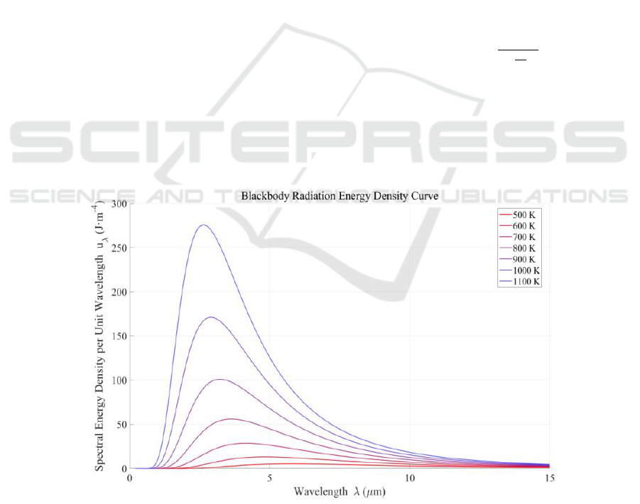
Planck coefficient. Figures 1 and 2 are the images
drawn according to Planck's formula.
Figure 1: Spectral energy density curves of blackbody radiation at different temperatures (Original).
IAMPA 2025 - The International Conference on Innovations in Applied Mathematics, Physics, and Astronomy
296
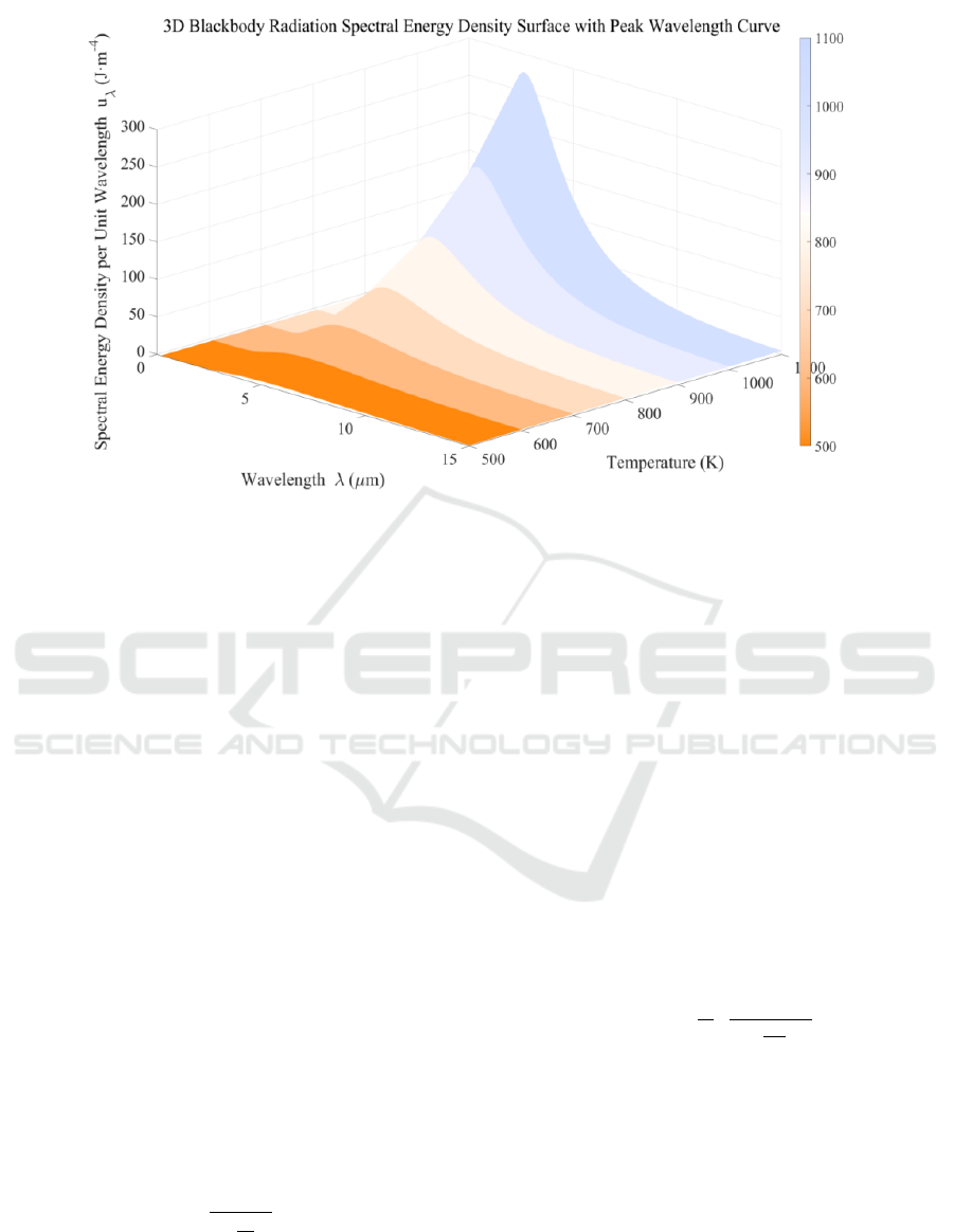
Figure 2: 3D surface of blackbody radiation spectral energy density as a function of wavelength and temperature (Original).
According to the Figures. 1, 2, it can be seen that
the monochromatic radiance has a unique extreme
value, and the product of its corresponding peak
wavelength and temperature is a definite constant
. That is, the temperature of the radiating body
can be determined simply by determining this value.
2.1.2 Total Radiometric Thermometry and
Luminance Thermometry
The total radiation method is based on the Stefan-
Boltzmann law, which integrates the spectral radiance
over the entire wavelength to obtain the full-wave
radiant energy flux per unit area. This means that the
temperature of the radiating body is determined by
measuring the total radiation:
(3)
Where
is the total amount of radiation
radiated per unit time from a unit area of a blackbody
at a temperature of , called the total radiance;
is the Stefan-
Boltzmann constant, and is the temperature of the
object. The temperature of the radiating body can be
determined as long as
is measured.
If Planck's formula is written in the form of
luminosity, i.e (Fan, 2016).
(4)
where
is the monochromatic radiance
measure of the spectrum. That is, the temperature of
the radiator is determined by measuring the radiant
luminance
of the radiator.
2.1.3 Multispectral Pyrometry
Multispectral thermometry, in contrast to total
radiometric thermometry, which collects the total
radiant energy in the infrared band (where the object
to be measured is approximated as an ideal
blackbody, i.e., the surface emissivity ε(λ) is
approximated to be 1), collects the intensity of
radiation at multiple wavelengths to derive the
temperature based on a mathematical model.
Consider general object surface emissivity
(5)
A system of equations can be constructed for the
intensity of radiation
measured at multiple
wavelengths
:
(6)
The temperature T and the unknown emissivity
ε(λ) can be solved for using numerical fitting.
2.2 Radiation Thermometry
Characteristics
As shown in Table 1, a comparison of the advantages
and disadvantages of the different methods is
demonstrated.
Principles and Applications of Optical Temperature Measurement Methods
297

Table 1: Comparison of different methods.
Temperature
measurement method
Main principle
Vantage
Drawbacks
Venn's method of
peak displacement
Calculation of temperature
by determining the peak
wavelength of radiation
The method is intuitive and simple
to calculate
Susceptible to background
noise and large measurement
errors
Luminance
thermometry
Measuring the brightness
of monochromatic
radiation to derive
temperature
Simple equipment, fast
measurement
Limited measurement
accuracy by relying only on
single-wavelength
information
Total radiometric
thermometry
Measurement of the total
radiant energy of the target
in all wavelength ranges
Wide coverage and high
temperature measurement
accuracy
Need to consider the spectral
response characteristics of
the detector, interference
from background radiation
Multispectral
pyrometry
Detects infrared radiation
in multiple wavelength
ranges to obtain spectral
information.
Reduces emissivity variations and
environmental interference errors,
making it suitable for high-
precision measurements.
Complexity of equipment
and calculations
2.3 Radiometric Thermometry
Applications
The radiation method of temperature measurement is
applicable to the temperature measurement of solid
surfaces such as blast furnace walls, workpiece
surfaces, cooling walls, etc.; the spectral line
broadening method and the molecular spectral line
rotation light intensity distribution method are
applicable to the measurement of the temperature and
its distribution in the furnace chamber. In the
industrial field, the application of optical temperature
measurement technology to the real-time monitoring
of blast furnace temperature is of great significance to
extend the life of the furnace, improve product
quality, and reduce energy consumption (Xu & Yang,
2012).
When smelting new steel grades, the first
steelmaking plant of Tianjin Tiangang Group Co.,
Ltd. needs to accurately determine the casting
temperature of steel when it is cast into ingot molds.
Due to the interference of smoke on site, the
measurement result of a conventional infrared
thermometer or optical pyrometer is more than 300
degrees lower than the actual value. If a thermocouple
thermometer is used for the measurement, the
thermocouple will be lost.
In order to solve this problem, the plant uses fiber
optic infrared thermometer, on-site temperature
measurement, the probe and fiber optic cable installed
in a metal protective tube with insulation, manipulate
the protective tube to the probe end of the steel close
to the steel (from the steel only 300mm) for
measurement. When the steel was ready to be
discharged, the fiber optic infrared thermometer was
calibrated alternatively with a consumable tungsten-
molybdenum thermocouple thermometer (the
consumable thermocouple thermometer was
calibrated at 1663°C and the fiber optic infrared
thermometer was calibrated at 1637°C, and the fiber
optic infrared thermometer was adjusted from 1637°C
to 1663°C). In the casting site, each ladle can be cast
eight groups of ingot molds, each group of about 8min
minutes. At the initial trial, eight casting temperatures
were measured, in chronological order: 1574°C,
1602°C, 1651°C, 1643°C, 1631°C, 1617°C, 1596°C,
1568°C. The measurement results correctly reflect the
law of casting temperature change with time, which
provides a reference for the development of the
smelting process for new varieties of steel. After a
number of casting temperature measurements, the
reproducibility of the program is good (Cao, 1998).
This composite scheme combines radiation
thermometry with traditional thermocouple
thermometry, and calibrates the fiber-optic infrared
thermometer with a consumable thermocouple of
higher accuracy to compensate for the initial
deviation of the instrument. According to the
measurement data, the scheme has better repeatability
and higher stability, and the loss is much lower than
the traditional thermocouple temperature
measurement scheme, and the accuracy is higher than
that of the scheme using only infrared temperature
measurement.
In addition, Zhan Chunlian et al. from the No. 205
Research Institute of China's weapon industry
proposed a high-speed multispectral real-time
temperature measurement technology program for
gas turbine blades, which solves the technical
problem that the high-speed and high-temperature
blades of domestic gas turbines cannot be monitored
IAMPA 2025 - The International Conference on Innovations in Applied Mathematics, Physics, and Astronomy
298
in real time. By constructing a comprehensive system
integrating high-speed multispectral detection, optical
decomposition, signal processing, and software
monitoring, Chunlian Zhan effectively solved the
limitations of traditional temperature measurement
methods in high temperature and high-speed
environments, and realized the goal of online real-
time temperature measurement and fault warning for
turbine blades (Zhang et al., 2018).
3 OPTICAL FIBER
THERMOMETRY
3.1 Principle of Distributed Fiber Optic
Thermometry
A distributed fiber optic temperature sensor obtains
spatial temperature distribution information by using
the principle of using light transmission in the optical
fiber can produce backward scattering. Injected into
the fiber with a certain energy and width of the laser
pulse, it is transmitted in the fiber at the same time
constantly produce backward scattering light waves,
the state of these light waves by the fiber where the
temperature of the scattering point and change the
scattering back to the light waves by wavelength
division multiplexing, detection and demodulation,
sent to the signal processing system can be real-time
display of temperature signals and by the optical fiber
light wave transmission speed and the backward light
return time can be on the These information can be
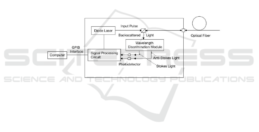
localized. The principle and structure of the block
diagram are shown in Figures 3 and 4 (Bo, 2024).
Rayleigh scattering, Raman scattering, and
Brillouin scattering are mainly involved in distributed
fiber optic temperature sensors.
Figure 3: This diagram illustrates the basic working principle and signal processing flow of a fiber-optic distributed
temperature sensing system based on Raman scattering (Original).
3.1.1 Rayleigh Scattering
Rayleigh scattering refers to the elastic scattering
phenomenon that occurs when an incident
electromagnetic wave (e.g., visible light) encounters
a tiny particle that is much smaller than its
wavelength, due to the excitation of the particle by an
external electric field that exhibits an electric dipole
radiation effect. Rayleigh scattering occurs when light
is incident into an optical fiber, where the
backscattered light can be used to monitor the
temperature distribution.
The backscattered optical power per unit length is:
(7)
Here, it is assumed that the fiber is homogeneous
and absorption is neglected. Where
, i.e.,
the time experienced by the optical pulse front from
injection to return to the injection end from the L point
on the optical fiber, different t corresponds to
different positions of the sensing fiber;
is the
speed of light in the optical fiber;
is the injected
optical pulse energy; is the backward scattering
factor; is the Rayleigh scattering coefficient
(proportional to the temperature), the change of the
temperature causes the change of the numerical
aperture of the optical fiber and the Rayleigh
scattering coefficient, thus affecting the backward
intensity of the scattered light. Based on this property,
the temperature distribution along the fiber can be
deduced by analyzing the intensity of the
backscattered signal returned at different times during
the transmission of light pulses in the fiber.
Rayleigh scattering temperature measurement
usually uses a pulsed laser light source and a beam
splitter between the laser and the fiber. When the
backscattered light returns to the injection end of the
optical pulse, the beam splitter reflects it back into the
detection optical path. The light signal is then
detected by an optical receiver system consisting of
an avalanche photo diode (APD) and a mutual
Principles and Applications of Optical Temperature Measurement Methods
299
impedance amplifier, and transmitted to a computer
for display after signal processing (Shi et al., 1997).
The structure of the device is shown in Figure 4.
Figure 4: This diagram shows a fiber-optic temperature
sensing system using a laser source, beam splitter, lenses,
and an optical receiver for temperature measurement and
digitization. (Original).
In distributed fiber optic temperature
measurement systems that use Rayleigh scattering,
the insensitivity of Rayleigh scattered light to
physical quantities of temperature leads to a lower
temperature resolution in systems that use this
scheme. Therefore, the technology of the distributed
fiber optic temperature measurement system based on
Rayleigh scattered light is gradually being eliminated.
When Brillouin scattering is used in the distributed
fiber-optic temperature measurement system, the
distributed temperature measurement system using
Brillouin scattering is not considered for the time
being because the corresponding variable physical
quantities in the Brillouin-scattered signals and the
changes in the temperature are sensitive to the
changes in the temperature, which are prone to cross-
influence. While in the distributed fiber optic
temperature measurement system based on Raman
scattering, its Raman scattering signal is only
sensitive to the temperature change around the fiber,
not easy to be interfered by other signals, and the
theoretical knowledge is relatively rich and perfect,
there is no special requirement for the type of optical
fiber, which is easier to realize and more practical
value compared to the above two techniques (Xia et
al., 2019).
3.1.2 Raman Scattering
Raman scattering is an inelastic light scattering
phenomenon, i.e., after the incident photon interacts
with matter, the frequency of the scattered photon
changes due to molecular vibration or lattice
vibration, resulting in Stokes and anti-Stokes
scattering, and its intensity is much lower than that of
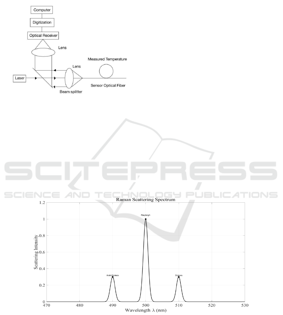
Rayleigh scattering, which is about as much as that of
Rayleigh scattering as shown in Figure 5.
Figure 5: This graph shows the Raman scattering spectrum with Rayleigh, Anti-Stokes, and Stokes peaks used for temperature
sensing (Original).
The following is the ratio (R) of anti-Stokes light
to Stokes light intensity for Raman scattering as a
function of temperature.
(8)
Where,
,
are the anti-Stokes and Stokes
light intensities of Raman scattering, respectively;
,
are the anti-Stokes and Stokes light
wavelengths of Raman scattering, respectively, which
IAMPA 2025 - The International Conference on Innovations in Applied Mathematics, Physics, and Astronomy
300

are only related to the fiber material: h is Planck's
constant; c is the speed of light;γis the Raman
frequency-shift wave number, which is only related to
the fiber material; k is Boltzmann's constant; and T is
the absolute temperature.
It can be seen that the optical intensity ratio R is
not affected by the incident laser power, injection
conditions and stress, and thus has good temperature
response characteristics. Therefore, the temperature
distribution along the fiber can be accurately
determined by analyzing the backward Raman
scattering intensity ratio of light pulses returned at
different times when they are transmitted in the fiber
(Hu, 2014).
3.2 Fiber Optic Thermometry in
Industry
Due to the distributed Raman temperature
measurement technology has the advantages of
intrinsic safety, easy to use, low maintenance cost,
strong anti-interference ability, large measurement
range, in the long-distance application scenarios can
be achieved Continuous and uninterrupted
temperature detection, can be quickly demodulated in
real time temperature, and can be arranged in the
environment of the complex and harsh environments,
and therefore is often used in oil and gas transmission
pipelines, large warehouses, large machinery,
Therefore, it is often used in oil and gas pipelines,
large warehouses, large machinery, power supply and
other scenarios.
In the field of liquefied natural gas (LNG) storage
tanks, the distributed fiber optic temperature
measurement and warning system is of great
significance in the safety management of the tank
area. Through the reasonable deployment of
distributed fiber optic temperature measurement can
be accurate measurement of the tank temperature, can
detect the temperature of the tank is too low point, in
order to achieve the LNG storage tank perlite filling
layer settlement of real-time online monitoring.
Distributed fiber optic temperature monitoring system
for LNG storage tank temperature monitoring and
early warning provides nearly perfect detection
performance (Bo, 2024). Table 2 shows the
evaluation results in three stages after application.
With the continuous improvement of the system, its
temperature measurement accuracy is significantly
improved, and the percentage of samples with error
within 5% is increased from 61.58% in stage 1 to
93.93% in stage 3. Meanwhile, the most negative
error and the most positive error are also reduced
significantly, indicating that the system error tends to
converge and the temperature measurement results
are more stable and reliable.
Table 2: Assessment results in the three phases (Xu, 2024).
Phase
Total number of
samples taken
Conformity (M
≤ 5%)
minuscule error
logarithmic
error
Phase 1
151
61.58%
-51.68%
75.58%
Phase 2
143
85.31%
-21.54%
17.50%
Phase 3
33
93.93%
-6.02%
1
4 CONCLUSION
Compared with the traditional contact temperature
measurement method, the optical temperature
measurement technology has the advantages of fast
response speed, good dynamic performance, and will
not destroy the surface temperature field of the
measured medium. Due to the uncertainty of the
emissivity of the surface of the object,
photothermometry may produce errors in the
temperature determination process. Therefore, the
relevant fields by combining the traditional
thermocouple calibration measurement, the
introduction of signal processing systems (including
APD and mutual impedance amplifier, etc.) to
achieve real-time display of temperature signals and
distribution of localization, combined with the
confocal measurement technology, but also to obtain
the temperature distribution of the three-dimensional
space, the computer automated control and other
programs. Thus, the optical temperature measurement
technology without interference, fast response, wide
measurement range of features to a greater extent to
benefit human production and life and scientific
research. In summary, the development trend of
optical temperature measurement technology is
toward higher accuracy, intelligence and automation,
multi-functional integration, better performance and
stronger environmental adaptability, the future will
bring more innovation and convenience for industrial
production and scientific research fields.
Principles and Applications of Optical Temperature Measurement Methods
301

REFERENCES
Bo, Z., 2024. Application of fiber optic temperature
measurement technology in engineering practice. Soda
Ash Industry, (05), 40–42.
Cao, B., 1998. Application of radiation temperature
measurement technology. Journal of Tianjin
Polytechnic Institute, (02), 58–60.
Fan, S., 2006. Infrared radiation temperature measurement
accuracy and error analysis. Changchun University of
Science and Technology.
Hu, Z., 2004. Principle and application of distributed fiber
optic temperature measurement system. China
Instrumentation, (07), 44–46.
Jianchun, X., Li, X., Wu, Y., Zhao, Y., Li, S., 2019.
Simultaneous measurements of distributed temperature
and discrete strain based on Hybrid Raman/FBG system.
Sensors and Actuators: A. Physical, 296.
Shi, W., Huang, D., Liu, D. 1997. Research and progress of
distributed fiber optic temperature sensors.
Semiconductor Optoelectronics, (04), 8–11.
Xie, Q., 2017. Comparison of several radiation temperature
measurement techniques. China Inspection and Testing,
25(04), 37–39+27.
Xu, X., Yang, X., 2012. Non-contact temperature
measurement technology. Science and Technology
Communication, (05), 159–160.
Xu, Z., 2024. Application of distributed fiber optic
temperature measurement system in monitoring of
perlite settlement in liquefied natural gas storage tanks.
Fluid Measurement and Control, 5(01), 31–34.
Zhan, C., Han, J., Lu, S. 2018. Research on multispectral
temperature measurement technology of ammunition
explosion flame temperature. Measurement Technology,
38(06), 48–52.
IAMPA 2025 - The International Conference on Innovations in Applied Mathematics, Physics, and Astronomy
302
