
A Comparative Study on Central Projection and Parallel Projection
Lily Yiting Huang
a
Hubei Wuchang Experimental High School, Wuhan, 430061, China
Keywords: Parallel Projection, Central Projection, Perspective Transformation, Descriptive Geometry, Computer
Graphics.
Abstract: A comprehensive comparative study focusing on central projection and parallel projection is conducted in
this paper. The two projection methods are systematically analysed from multiple perspectives including their
physical definitions, fundamental principles, mathematical theorems, geometric properties, algorithmic
implementations, and practical applications. The differences and connections between the two projections are
elucidated in detail. Their advantages and disadvantages across various disciplines are also explored, and the
study of an application example is given. It is demonstrated that central projection, which simulates human
visual perception, provides more realistic scene perception and is suitable for visual arts production field, but
non-linear transformations and more complex computation are involved, leading to an inaccurate geometric
measurement. In contrast, parallel projection preserves geometric proportions through linear transformations
with simpler computations, but lacks spatial depth perception, rendering it ideal for precision-dependent fields
such as measurement and manufacturing. Finally, the application of integration on central projection and
parallel projection methods and their development in the future are explored. This study provides valuable
references and insights for related research fields.
1 INTRODUCTION
Projection is the process of mapping a three-
dimensional object in space onto a two-dimensional
plane. The shadow formed by light rays illuminating
an object and casting onto a screen behind it is
referred to as a projection. Central projection and
parallel projection are two fundamental methods of
projection theory, widely applied in fields such as
geometry, computer graphics, engineering drafting,
photography, painting, and artistic creation (Müller,
et al., 2021; Liu et al., 2024; Garcia et al., 2019). Due
to their distinct definitions and principles, these two
projection methods exhibit different characteristics
and are suited to different scenarios. However, they
both play important roles in practical applications.
This paper conducts a comparative study of these two
projection methods by analysising their physical
definitions and principles, geometric and
mathematical properties, computational approaches,
and application feilds. Furthermore, their future
development prospects are explored.
a
https://orcid.org/0009-0000-6110-3853
2 DEFINITIONS, PRINCIPLES,
AND CHARACTERISTICS
The essence of projection is transmitting the contours
of an object onto a designated plane through a set of
light rays (projection lines). Therefore, three essential
elements are required to form a projection. The fisrt
factor is projection center that can be regarded as the
light source. For instance, in the case of a shadow cast
by sunlight, the sun serves as the projection center.
The second is projection object that is being
projected. It may consist of geometric elements such
as points, lines, or surfaces, or a three-dimensional
solid. The third is projection plane, a receiving
surface where the image is formed after the light rays
pass through the object. It can be a ground surface, a
wall, a drawing sheet, etc.
The spatial position of the projection center and
the direction of the projection lines influence the
shape and size of the projected image on the plane.
Based on the mutual relationships between projection
lines, projections are classified into central projection
Huang, L. Y.
A Comparative Study on Central Projection and Parallel Projection.
DOI: 10.5220/0013822100004708
Paper published under CC license (CC BY-NC-ND 4.0)
In Proceedings of the 2nd International Conference on Innovations in Applied Mathematics, Physics, and Astronomy (IAMPA 2025), pages 205-212
ISBN: 978-989-758-774-0
Proceedings Copyright © 2025 by SCITEPRESS – Science and Technology Publications, Lda.
205
(perspective projection) and parallel projection
(Foley et al., 2018; Coxeter et al., 2003).
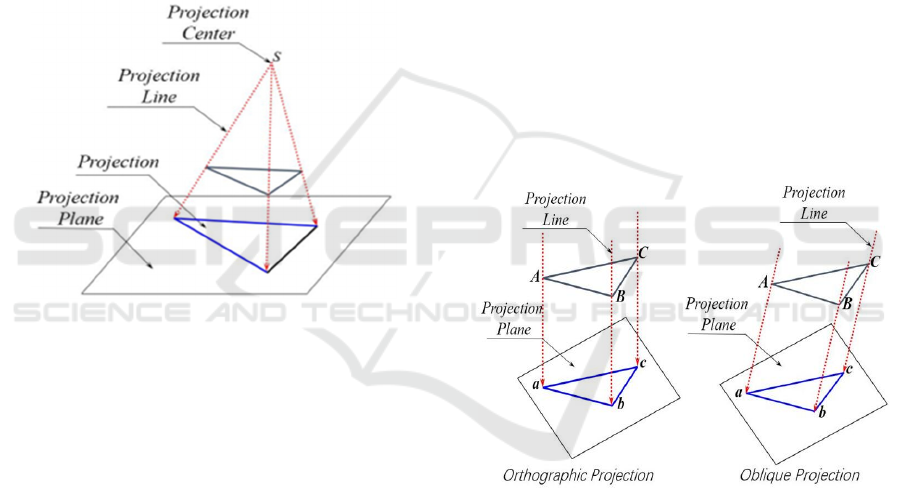
2.1 Central Projection
Central projection refers to a projection method in
which light rays emanate from a single point (the
projection center) and diverge radially, passing
through an object and intersecting a receiving surface
to form a perspective relationship. Geometrically, this
process involves extending the lines connecting each
point on the object to a fixed projection center until
they intersect a plane that does not contain the
projection center. The set of intersection points
constitutes the central projection of the object onto
that plane, as illustrated in figure 1.
Figure 1: Central Projection (Picture credit: Original).
In central projection, since all projection lines
converge at a single point (the projection center), the
varying distances between different parts of the object
and the projection center result in non-uniform
scaling, causing changes in the size and shape of the
projected image, whose actual dimensions and angles
may undergo nonlinear distortion (Carlson, 2003).
Parallel lines in the original object may intersect at
vanishing points on the projection plane, leading to
significant deviations between the projected image
and the original object. These Characteristics, to some
extent, compromise the metric accuracy of central
projection, limiting its widespread application in
classical solid geometry. However, the resulting
transformations enhance visual intuitiveness and
spatial realism, aligning with human visual
perception, e.g., near-far size attenuation.
Consequently, central projection is extensively
employed in artistic domains, such as painting and
photography, where it preserves a naturalistic
resemblance to the original object while emphasizing
depth and perspective (Peacock, 2001).
2.2 Parallel Projection
When the light source at the projection center is
relocated to infinity, all projection rays become
mutually parallel and intersect the projection plane at
a fixed angle, which is termed parallel projection. As
illustrated in figure 2, parallel projection can further
be categorized into two subtypes:
Orthographic Projection
The projection lines are perpendicular to the
projection plane. For example, the standard
engineering multi-view drawings (including front,
top, and side views). This method preserves the true
dimensions and shapes of objects, making it
indispensable for technical drafting.
Oblique Projection
The projection lines intersect the projection plane
at an oblique angle (90°). For example, cabinet
oblique projection which retains partial depth
perception exhibits less metric accuracy compared to
orthographic projection.
Figure 2: Parallel Projection (Picture credit: Original).
In parallel projection, the shape and size of objects
maintain proportional consistency on the projection
plane without scaling effects caused by varying
distances. Due to its superior metric properties,
relatively simple projection rules, and ease of
understanding and drafting, parallel projection is
broadly applied in fields requiring precise proportions
and resistance to perspective distortion. These
applications include engineering drawings,
mechanical manufacturing, cartography and
surveying, architectural design, and computer
graphics (Liu, 2022; Zhang et al, 2008; Luo et al.,
2009).
IAMPA 2025 - The International Conference on Innovations in Applied Mathematics, Physics, and Astronomy
206
3 MATHEMATICAL THEOREMS
AND RELATED PROPERTIES
3.1 Fundamental Theorems and
Properties of Central Projection
Collinearity Preservation
If three points in space lie on a straight line, their
central projections will remain collinear (or all
converge to points at infinity).
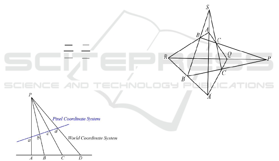
Cross-Ratio Invariance
In central projection, the cross ratio of any four
collinear points remains invariant. This theorem holds
a central position in projective geometry and ensures
accurate proportional transformations in perspective
projection.
As illustrated in figure 3, four collinear points
𝐴,𝐵,𝐶,𝐷 are projected onto another line as 𝑎,𝑏,𝑐,𝑑
via central projection. While the lengths of projected
segments change and the ratios of individual
segments are not preserved, the cross ratio remains
invariant, that is:
(
𝐴
𝐵
,
𝐶𝐷
)
=
𝐶𝐴
𝐶𝐵
𝐷𝐴
𝐷𝐵
=
𝑐𝑎
𝑐𝑏
𝑑𝑎
𝑑𝑏
(1)
Here, all segments are treated as directed lengths with
signed magnitudes. Definitions of world coordinates
and pixel coordinates are provided in Section 4.
Figure 3: Cross-Ratio in Central Projection (Picture credit:
Original).
The cross-ratio invariance has significant
applications in computer vision, photogrammetry,
and robot navigation. Specific use cases include sun
positioning systems (based on shadow
measurements) (Zhang et al., 2015), structured-light
3D reconstruction (light-plane calibration) (Chen et
al., 2018), Camera self-calibration (using vanishing
points) (Cipolla et al., 1999).
Nonlinearity
Central projection is not a linear transformation
(except when the projection center is at infinity, in
this case, it degenerates into parallel projection).
Notably, As introduced in Desargues’ theorem, in
homogeneous coordinates, central projection can be
represented as a fractional linear transformation.
Non-Preservation of Distances and Angles
Central projection distorts metric properties (e.g.,
lengths, angles) of geometric shapes.
Points at Infinity
In projective geometry, central projection maps
lines parallel to the projection plane to vanishing
points at infinity, thereby extending Euclidean space
into projective space.
Desargues’ Theorem
If the lines connecting corresponding vertices of
two triangles meet at a single point (perspector), then
the intersections of their corresponding edges lie on a
straight line (perspectrix), and vice versa.
Figure 4: Desargues Theorem (Picture credit: Original).
As illustrated in figure 4, the author considers two
triangles △𝐴𝐵𝐶 and △ 𝐴′𝐵′𝐶′ . If the connecting
lines of corresponding vertices 𝐴𝐴′,𝐵𝐵′,𝐶𝐶′
intersect at a common point 𝑆 (the perspector), the
triangles exhibit point perspective. Conversely, if the
intersections of corresponding edges denoted 𝑅𝑄𝑃 lie
on a straight line (the perspectrix), they exhibit line
perspective. A pair of triangles are perspective if
either condition is satisfied (Coxeter, 2003; Hartley,
2018).
The conditions and conclusions in Desargues'
theorem are mutually inverse and implicative, which
demonstrates the fundamental principle of point-line
duality in projective geometry. This self-dual
characteristic establishes the foundational status of
Desargues' theorem in projective geometry and
extends its practical utility (Ma, 2011).
Desargues' theorem describes the specific
geometric relations satisfied by two triangles under
A Comparative Study on Central Projection and Parallel Projection
207

the condition that central projection preserves
collinearity and cross-ratio while potentially altering
metric properties such as distances and angles. It
reveals profound properties that remain invariant
when observing geometric figures under different
projection centers. These properties are independent
of specific length or angle measurements, relying
solely on the relative positional relationships of the
figures (Xing et al., 2004).
From an algebraic perspective, Desargues'
theorem reflects the preservation of linear
dependence. In homogeneous coordinates, collinear
points correspond to linearly dependent vectors,
while concurrent lines correspond to linearly
dependent linear equations. The validity of
Desargues' theorem stems from that central
projections corresponds to linear transformations in
vector space, which preserve this dependency
structure (Yu et al., 2011; Sturmfels et al., 2020).
Mathematical Formulation and Transformation
Matrices
In computer graphics, central projection is widely
used to simulate human visual perception or camera
observation of 3D scenes. Its mathematical
formulation can be implemented via matrices
transformation that generally expressed in
homogeneous coordinates to enable perspective
division.
Assume that:
The projection center (camera optical center) is
located at the origin O(0,0,0).
The projection plane is defined as the 𝑧=𝑓 plane
(where 𝑓>0).
A spatial point 𝑃(𝑋,𝑌,𝑍) is projected onto the
imaging plane as 𝑝(𝑥,𝑦).
Based on the similar triangle principle (see figure
5, right), the following relationships are obtained:
=
,
=
(2)
The solving for the projected coordinates is:
𝑥=
∙
, 𝑦=
∙
(3)
Here, 𝑍 denotes the depth of point 𝑃, which governs
the scaling effect of the projection and serves as the
divisor in perspective normalization.
When 𝑍=0, the projected point lies behind the
projection center, making it geometrically invalid.
When 𝑍=∞, the projected point approaches a
vanishing point. In Euclidean space, infinite distances
cannot be represented with finite coordinates.
To uniformly describe all points while linearizing
nonlinear central projections, homogeneous
coordinates are introduced (Hartley et al., 2004):
The 3D point 𝑃(𝑋,𝑌,𝑍) is represented as
𝑃(𝑋,𝑌,𝑍,1) in homogeneous coordinates.
The 2D point 𝑃(𝑥,𝑦) is represented as 𝑃(𝑥,𝑦,1)
in homogeneous coordinates.
Using matrix algebra, central projection can be
expressed as a linear transformation in homogeneous
coordinates. The projected point in homogeneous
coordinates is:
𝑥′
𝑦′
𝑤′
=
𝑓
0
00
0
𝑓
00
00
10
𝑋
𝑌
𝑍
1
=
𝑓
𝑋
𝑓
𝑌
Z
(4
)
To normalize 𝑥′ , 𝑦′ and 𝑤′ , 2D coordinates are
obtained:
𝑥=
=
∙
, 𝑦=
=
∙
(5
)
3.2 Fundamental Theorems and
Properties of Central Projection
In contrast to central projection, parallel projection
does not exhibit vanishing points but preserves more
geometric invariants, with its core parallelism and
proportionality preservation. These properties make
parallel projection indispensable in engineering
drafting, mechanical design, and scientific
visualization.
Parallelism Preservation
Two parallel lines in space are remain parallel in
the projection plane unless they are parallel to the
projection direction. Lines parallel to the projection
direction degenerate to points.
The parallel preservation theorem is one of the
most critical and widely applied properties of parallel
projection. It guarantees the invariance of parallel
relationships in projective transformations, providing
the theoretical foundation for operations such as
dimension annotation and view correspondence in
engineering drawings. For instance, parallel edges of
mechanical parts remain parallel in orthographic
projections (Shah, 2020).
Proportionality Preservation
Parallel projection preserves the proportional
lengths of line segments.
The proportionality preservation theorem, rooted
in the linearity of affine transformations, guarantees
the accurate transfer of geometric relationships. This
principle is extensively applied in engineering design,
architectural drafting, and computer graphics.
IAMPA 2025 - The International Conference on Innovations in Applied Mathematics, Physics, and Astronomy
208

Orthographic projection preserves angles on the
projection plane, whereas oblique projection
maintains angles only along specific directions (e.g.,
axial directions), with potential distortion in other
orientations.
Linearity Theorem
Parallel projection is a linear transformation
expressible as an affine transformation matrix. Its
transformation matrix combines a linear matrix and a
translation matrix, classified as an affine
transformation. This affine structure underpins the
validity of the parallelism preservation theorem.
Mathematical Formulation and
Transformation Matrices
Orthographic projection is the simplest form of
parallel projection, where the mathematical
expression of its transformation matrix for front-view
projection directly discards the 𝑍 coordinate.
Let the object point be 𝑃(𝑋,𝑌,𝑍), projected onto
the plane 𝑧=0 with projection point 𝑝(𝑥,𝑦). The
orthographic projection transformation is given by:
100
010
000
𝑋
𝑌
𝑍
=
𝑥
𝑦
0
(6)
Oblique projection may introduce shear distortion
while maintaining parallelism, and can be achieved
by superimposing orthographic projection with shear
transformation (Foley et al., 2018; Shirley et al.,
2016). Let the shear parameters be -a and -b, then the
oblique projection is expressed as:
10−𝑎
01−𝑏
000
𝑋
𝑌
𝑍
=
𝑥
𝑦
0
,
𝑎=𝑐𝑜𝑡𝜃
𝑥
𝑏=𝑐𝑜𝑡𝜃
𝑦
(7)
where 𝜃
( 𝜃
) denote the angle between the
projection direction and the 𝑥 ( 𝑦) axes.
For cabinet Projection, 𝜃=45
°
,𝑎=𝑏=1.
For cavalier Projection, 𝜃=63.4
°
,𝑎=𝑏≈
0.5.
Thus, the parameter 𝑐𝑜𝑡𝜃 governs the degree of
distortion in oblique projections.
3.3 Comparative Analysis of Central
and Parallel Projections
Based on the comprehensive analysis of the
definitions, principles, mathematical theorems, and
properties of both central and parallel projections, it
can be found that these two projection methods
exhibit both fundamental differences and intrinsic
connections. The detailed comparative analysis is
enumerated as follows.
From a definitional perspective: Central
projection features a finite distance between the
projection center and the projection plane, with non-
parallel projection lines converging at a single point,
and possesses vanishing points. Parallel projection is
characterized by an infinite projection distance
between the center and plane, resulting in mutually
parallel projection lines with no vanishing points.
From a mathematical perspective: Central
projection is a nonlinear transformation in Euclidean
coordinate systems but can be linearized through the
introduction of homogeneous coordinates, allowing
for matrix-based expression. Parallel projection is
inherently a linear transformation, and its
computation is relatively simple. Whereas central
projections require perspective division and
normalization, which make its computation becoming
complex.
From a geometric perspective: For collinearity
preservation, both central (perspective) and parallel
projections maintain collinearity. For parallelism
preservation, parallel lines of central projection may
converge at vanishing points, but parallel lines of
parallel projection remain strictly parallel. For length
proportionality, central projection exhibits
perspective foreshortening with nonlinear scaling in
distance, while cross-ratios remain preserved. In
contrast, orthographic parallel projection maintains
true length for segments parallel to the projection
plane, and oblique parallel projection allows
adjustable scaling along axial directions. For angular
preservation, central projection causes angular
distortion. Whereas orthographic parallel projection
preserves all angles, and oblique parallel projection
only maintains axial angles, with potential distortion
in other orientations.
Desargues’ theorem and projection applications:
Desargues’ theorem extends the Euclidean plane to
the projective plane by introducing the concepts of
points at infinity and the line at infinity, embodying
the inclusivity and inherent unification of projective
geometry.
Owing to these distinct properties, the two
projection methods exhibit different application
performances. Central projection is typically
employed in scenarios requiring visual effects or
artistic expression, whereas parallel projection is
primarily utilized in precision-dependent applications
such as engineering drawings. Currently, the
integration technique of both projection methods
which combines geometric accuracy and visual
realism has been developed and applied in multiple
domains including computer graphics, architectural
visualization, medical imaging, augmented reality, as
A Comparative Study on Central Projection and Parallel Projection
209
well as cartography and geographic information
systems. Multidimensional representation is achieved
by this hybrid approach of applying parallel
projection to some objects while using perspective
projection for others within the same scene.
4 CASE STUDIES OF CENTRAL
PROJECTION APPLICATION
Due to space limitations, application case of central
projection is exclusively analyzed and discussed in
this section.
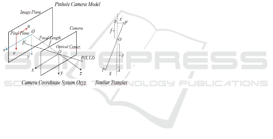
A canonical application of central projection is the
pinhole camera model, whose physical prototype
forms inverted images on the projection plane
through light rays passing via a small aperture, as
illustrated in figure 5.
Figure 5: Pinhole Camera Model (Szeliski, 2022).
The process of digital camera image capture is
fundamentally an optical imaging procedure, with the
pinhole imaging model being the most widely
adopted for camera imaging. This model involves
four coordinate systems: the world coordinate system,
camera coordinate system, image coordinate system,
and pixel coordinate system, along with their mutual
transformations (Hartley et al., 2004; Szeliski, 2022).
The world coordinate system (𝑋,𝑌,𝑍 ), also
referred to as the global coordinate system, defines
the camera's position in 3D space, while the camera
coordinate system originates at the optical center O
with axes x, y, and z. The image coordinate system is
established on the imaging plane 𝑂′𝑥′𝑦′ with
coordinates (𝑥′,𝑦′,𝑧), and the pixel coordinate
system, essentially a matrix-based system, has its
origin at the top-left corner of the image with axes 𝑢
and 𝑣 parallel to 𝑥′ and 𝑦′, where (𝑢,𝑣 )represents
the pixel's row and column indices in the matrix.
Here, 𝑃(𝑋,𝑌,𝑍 ) denotes a point in the world
coordinate system, and 𝑃′ represents its
corresponding projected image point.
The transformation of spatial points from the
world coordinate system to the camera coordinate
system belongs to a rigid-body transformation,
involving solely translation T and rotation R. The
rotation matrix R between the two coordinate systems
can be derived from the axial rotation angles of the
three coordinate axes, while the translation T is
determined by the positions of their coordinate
origins.
The transformation from pixel coordinates (𝑢,𝑣 )
to image coordinates(𝑥′,𝑦′) incorporates both
scaling and translation due to their distinct origins and
scale conventions. The translation parameters and
scaling factors can be calculated based on the
positional relationship between the origins of the two
coordinate systems and the physical dimensions of
pixels in the image coordinate system.
After completing the above two transformations,
an additional step is required to achieve the full
transformation from world coordinates to pixel
coordinates: the transformation from camera
coordinates (𝑥,y ) to image coordinates (𝑥′,𝑦′). This
conversion corresponds precisely to the central
projection transformation, as illustrated in figure 5
(right panel).
Based on the principle of similar triangles, the
transformation relationship can be derived, that is
formula (3) and (5) along with transformation (4) in
Section 3.1.
In the process of the complete transformation,
𝑅 and 𝑇constitute the extrinsic parameters of the
camera, defining its pose in the world coordinate
system. The intrinsic parameters, encapsulated in the
calibration matrix 𝐾 , are derived from the focal
length 𝑓 and the transformation coefficients between
image and pixel coordinates. Both intrinsic and
extrinsic parameters can be estimated through
established calibration procedures (Zhang, 2000).
Algorithm is implemented and executed
according to the above steps:
The extrinsic parameters of the rotation matrix 𝑅
and translation vector 𝑇
for the world-to-camera
coordinate transformation are computed first.
Subsequently, the intrinsic parameter calibration of
the projection matrix 𝐾 encapsulating focal length
𝑓 and image-to-pixel coordinate conversions is
estimated. Finally, perspective normalization is
performed through perspective division to obtain
normalized coordinates.
The practical implementation can be achieved
through programming in various computer languages.
IAMPA 2025 - The International Conference on Innovations in Applied Mathematics, Physics, and Astronomy
210

In this paper, MATLAB programming is adopted, but
the source code is not provided here due to space
constraints.
5 CONCLUSION
In summary, as two fundamental projection methods
in projection theory, parallel projection and central
projection differ in their definitions, underlying
principles, mathematical formulations, exhibited
properties, and application domains.
Mathematically, central projection is based on
perspective geometry, where all projection lines
converge at the viewpoint, forming a conical
projection structure. The most distinctive feature that
distinguishes it from parallel projection is the
convergence of parallel lines at vanishing points on
the projection plane. This results in an inverse
relationship between object size and the distance from
the object point to the projection center (viewpoint),
producing the characteristic 'foreshortening' visual
effect. By contrast, parallelism in space is preserved
in parallel projection, whether orthographic or
oblique, with all projection lines remaining parallel,
where projected dimensions are independent from the
distance (the depth compression ratio of cabinet
oblique projection is 0.5). It is this fundamental
dichotomy dictates that dictates their divergent
applications.
Visually, central projection aligns with human
visual perception by generating spatial depth cues,
making it suitable for applications requiring realism,
such as creating cinematic visual effects and
discerning accurate architectural spatial relationships
in through strategically placed vanishing points. In
contrast, although parallel projection lacks depth
perception, its ability to preserve geometric invariants
makes it indispensable for technical drawings.
Orthographic multi-view projections provide
dimensional accuracy for mechanical component
designs, while axonometric projections in
architectural drafting offer three-dimensional
visualization without perspective distortion.
With the development of science and technology,
projection technology has also been evolving and
innovating. The integration technology combining
these two projection methods is being applied in a
growing number of fields. It is believed that both
projection approaches will further develop toward
greater intelligence, automation, and cross-domain
integration, enabling broader applications in the
future.
REFERENCES
Carlson, W. E., 2003. A Critical History of Computer
Graphics and Animation (Online textbook). Ohio State
University, 87-92.
Chen, L., Zhang, W. W., Li, H., Xu, J., 2018. Plane-Based
Calibration for Structured Light Systems Using Cross-
Ratio Constraint. Optics and Lasers in Engineering,
110, 1-8.
Cipolla, R., Drummond, T., Robertson, D. P., Blake, A.,
1999. Camera Calibration from Vanishing Points in
Images of Architectural Scenes. IEEE CVPR, 2, 382-
387.
Coxeter, H. S. M., 2003. Projective Geometry. Springer,
Berlin, 2
nd
Edition, 23-61.
Foley, J. D., Van Dam, A., Feiner, S. K., Hughes, J. F.,
2018. Computer Graphics: Principles and Practice.
China Machine Press. Beijing, 3
rd
Edition, 272-275.
Garcia, E. S., He, M. M., Mueller, k.,2019. Artistic Style
Transfer with Controlled Perspective Distortion.
Journal of Computer Graphics Techniques,18(3), 72-
89.
Hartley, R., Zisserman, A., 2004. Multiple View Geometry
in Computer Vision. Cambridge University Press,
Cambridge, 2
nd
Edition, 155-160+225-228.
Liu, H. W., 2022. Application of Projection Technology in
Computer-Aided Design and Programming for Stone
Product Processing. Stone, 3, 26-31+39.
Liu, Y., d., Lü, Y. W., Du, B. J., Gong, X. R., Huang, X.,
2024. Projection Center and Triple Difference
Detection Method of T-Type Photoelectric Theodolite.
Acta Optica Sinica, 44(2),1-10.
Luo, W., Deng, X. W., 2009, The teaching discussion on
the building direction in civil engineering major. Shanxi
Architecture, 35 (11), 194-196.
Ma, Y., F., 2011. Popularization on Application of
Desargues Theorem and its Inverse. Journal of Gansu
Lianhe University (Natural Sciences), 25(2), 95-97.
Müller, S., Zhang, Y., 2011. Comparative Analysis of
Orthographic vs Perspective Projection in CAD-Based
Industrial Design. Computer-Aided Design, 130, 45-58.
Peacock, K., Druckrey, T., 2001. Projective
Transformations in Digital Art. Leonardo, 34(3), 203-
208.
Shah, J. J., 2020. Parametric and Feature-Based
CAD/CAM: Concepts, Techniques, and Applications.
ASME Press, New York, 2
nd
Edition, 189-201.
Shirley, P., Marschner, S., Ashikhmin , M., 2016.
Fundamentals of Computer Graphics. AK Peters/CRC
Press, Boca Raton, 4
th
Edition, 135-153.
Sturmfels, B., Pajdla, T., Kileel, J., 2020. Algebraic
Geometry of Computer Vision. Foundations of
Computational Mathematics, 20(5), 1123-1150.
Szeliski, R., 2022. Computer Vision: Algorithms and
Applications. Springer, Berlin, 2
nd
Edition, 52-55.
Xing, Y. F., Hu, Z. Y., Zhang, J., 2004. Projective
Invariants for Vision-Based Measurement. IEEE
Transactions on Pattern Analysis and Machine
Intelligence, 26(11), 1454-1460.
A Comparative Study on Central Projection and Parallel Projection
211

Yu, J. B., Ponce, J., Hebert, M., 2011. Algebraic
Foundations of Projective Geometry in Computer
Vision. Journal of Mathematical Imaging and Vision,
39(2), 120-135.
Zhang, S. X., Ye, H., 2008. Projection and Painting Art.
Journal of Engineering Graphics, 2008(5), 107-110.
Zhang, Y., Chen, X. D., Wang, L., 2015. Shadow-Based
Geometric Calibration of Sun Sensors Using Cross-
Ratio Invariance. IEEE Transactions on
Instrumentation and Measurement, 64(6), 1520-1531.
Zhang, Z. Y., 2000. A Flexible New Technique for Camera
Calibration. IEEE Transactions on Pattern Analysis
and Machine Intelligence, 22(11), 1330-1334.
IAMPA 2025 - The International Conference on Innovations in Applied Mathematics, Physics, and Astronomy
212
