
From Algebraic Synthesis and GRAFCET to Logical Controller
Design in ST Code (IEC 61131-3)
Mathieu Roisin
1a
, Dimitri Renard
1b
, David Annebicque
1c
, Bernard Riera
1d
and Pierre-Alain Yvars
2e
1
CReSTIC, University of Reims Champagne-Ardenne, Reims, France
2
QUARTZ, ISAE-Supméca, Saint-Ouen, France
Keywords: PLC, Control Design, GRAFCET, Algebraic Synthesis.
Abstract: This paper addresses the problem of logic controller synthesis and the automatic generation of code compliant
with the IEC 61131-3 standard, specifically Structured Text (ST) code. From a methodological perspective,
two complementary approaches can be used to tackle this problem. The extensional approach explicitly
represents the solution using models such as GRAFCET or Petri nets. In contrast, the intensional approach
defines the solution space through a set of rules or constraints, without enumerating all possible solutions.
Among intensional techniques, algebraic synthesis stands out as a formal method to derive controllers from
specifications. We argue that combining extensional and intensional approaches leads to more efficient and
robust controller design. To this end, we propose a hybrid workflow that integrates an extensional model
(GRAFCET) with an intensional method (algebraic synthesis), enabling the automatic generation of IEC
61131-3 ST code. To support this workflow, we have developed two software tools: GReSTIC, for code
generation and simulation, and BooG, for the algebraic synthesis and fusion of the two approaches. The
proposed methodology is validated through a case study, demonstrating the automatic generation of reliable
and standard-compliant ST code.
1 INTRODUCTION
The advent of Industry 4.0 (Koren, 2010) is
transforming industrial system design and operation.
As production systems grow more complex, robust,
integrated, and automated methods are essential to
account for technical, logical, and physical
constraints early on. Automation relies on developing
reliable and safe logic controllers tailored to system
needs.
In this context, our work focuses on synthesizing
logic controllers and automatically generating PLC
code (Jones, 1998) compliant with IEC 61131-3
(John & Tiegelkamp, 2001) We explore intensional
approaches, which define control problems through
rules and constraints rather than explicitly
representing solutions (e.g., GRAFCET (IEC 60848,
a
https://orcid.org/0009-0009-7182-1205
b
https://orcid.org/0009-0009-2265-9176
c
https://orcid.org/0000-0002-0706-0714
d
https://orcid.org/0000-0003-1294-874X
e
https://orcid.org/0000-0002-7131-6796
2012) (Schumacher, 2013), or Petri nets (Teng &
Black, 1990), allowing solvers to compute solutions
without exhaustive enumeration. We argue that
integrating both extensional and intensional methods
enables more efficient and robust controller design.
This article is structured as follows. We first
present extensional and intensional approaches to
logic control synthesis, then focus on an intensional
method based on algebraic synthesis. Next, we
introduce a workflow combining GRAFCET
(extensional) and algebraic synthesis (AS)
(intensional) (Ranger, 2021), supported by two tools:
GReSTIC, for generating ST code from GRAFCET,
and BooG, for merging GRAFCET and AS results.
Finally, the workflow is applied to a case study,
generating ST code for a virtual PLC controlling a
simulated manufacturing system.
494
Roisin, M., Renard, D., Annebicque, D., Riera, B. and Yvars, P.-A.
From Algebraic Synthesis and GRAFCET to Logical Controller Design in ST Code (IEC 61131-3).
DOI: 10.5220/0013817800003982
Paper published under CC license (CC BY-NC-ND 4.0)
In Proceedings of the 22nd International Conference on Informatics in Control, Automation and Robotics (ICINCO 2025) - Volume 1, pages 494-501
ISBN: 978-989-758-770-2; ISSN: 2184-2809
Proceedings Copyright © 2025 by SCITEPRESS – Science and Technology Publications, Lda.

2 MODELLING METHODS AND
TOOLS FOR LOGIC
CONTROLLER SYNTHESIS
According to the literature, there are two general
ways of solving a problem: by extension or by
intension (Peregrin, 2007). The distinction lies in how
the set of possible solutions is represented and
processed.
The extensional approach explicitly describes
candidate solutions. In logic controller design,
GRAFCET diagrams graphically specify action
sequences and transitions, representing a concrete
solution.
In contrast, the intensional approach specifies
rules or constraints that valid solutions must satisfy
without enumerating them. In controller synthesis,
algebraic modeling expresses desired behavior as
logical constraints, and a solver generates correct-by-
construction implementations.
Logic controller design can use extensional,
intensional, or both approaches. Extensional methods
are directly interpretable and align with industry,
while intensional methods offer flexibility and
automation for complex systems. Combining them
leverages both strengths for more efficient and
reliable control logic synthesis.
This dual perspective lays the foundation for the
methodology proposed in this paper, which leverages
both extensional and intensional models to support
automated and robust controller generation.
2.1 Extensional Approach
Extensional logic controller design involves formally
specifying a candidate solution, including system
states and transitions, and systematically verifying its
behavior against functional and safety requirements.
GRAFCET (Schumacher, 2013), Petri nets (Teng &
Black, 1990) and state machines (Rabin & Scott,
1959) are all based on this approach, which is widely
used to control discrete-event systems. Today, this
method is the most widely used in the industrial world
2.2 Intensional Approach
The intensional approach to logic controller design
consists in formulating system requirements as a set
of constraints on variables representing the unknowns
of the problem. One or more admissible solutions can
then be generated using an automatic solver, which
ensures that each solution satisfies all the defined
constraints.
In the field of automation engineering, methods
such as Supervisory Control Theory (SCT) (Ramadge
& Wonham, 1987) or Algebraic Synthesis (AS)
(Hietter, 2009) follow this intensional paradigm.
However, these methods are still rarely used in
industry, where they are often overshadowed by more
operational, but often empirical, extensional
approaches.
A key advantage of intensional methods is that
they guarantee correct solutions: if the specification
is valid, any derived solution satisfies it.
2.3 Advantages and Disadvantages
Both extensional and intensional approaches have
advantages and limitations. Extensional methods use
intuitive graphical models and generate logic
efficiently implementable on a PLC, but require
manually specifying a single solution, which is error-
prone, needs to be verified (e.g., GRAFCET
verification, Roussel & Lesage, 1996), and hard to
generalize. Intensional methods are declarative and
provide formally correct solutions, but defining
constraints is complex, PLC implementation can be
less efficient, and sequential or procedural behaviors
are harder to represent.
Given their complementary strengths, we propose
combining extensional and intensional approaches.
GRAFCET handles simple action sequences well,
while intensional methods better address complex
requirements like safety constraints or task
synchronization.
3 ALGEBRAIC SYNTHESIS OF
LOGICAL CONTROLLER
In this section, we discuss the algebraic synthesis
(AS) method, which plays a key role in the broader
workflow that will be presented later in this paper.
Algebraic synthesis uses an intensional approach,
defining constraints over known variables (e.g.,
sensors) and unknown variables (e.g., actuators) to
identify all valid solutions (by solving the problem).
Developed for controller synthesis, it expresses
output variables as logical functions of inputs and
internal states (Hietter, 2009) (Roussel & Lesage,
2012) (Roussel & Lesage, 2014).
3.1 Fundamental Principles
The algebraic synthesis (AS) method is based on
From Algebraic Synthesis and GRAFCET to Logical Controller Design in ST Code (IEC 61131-3)
495

Boolean algebra. It operates over a set of Boolean
variables divided into two categories:
- Known Variables: Read-only inputs, such as
sensors or previous controller states.
- Unknown Variables: Write-only outputs, such as
actuators or internal controller states.
A set of Boolean constraints is defined over these
variables using connectors (equality (=), implication
(=>)) and logical operators (OR (+), AND (.) and
NOT (-). The goal of algebraic synthesis is to
compute all Boolean expressions for each unknown
variable as a function of the known variables, in such
a way that all constraints are satisfied.
The method consists of different steps presented
in the (Hietter, 2009) thesis. In the end each unknown
variable is ultimately expressed as a function of
known variables and a set of Boolean parameters.
Different parameter values yield different solutions.
The complete set of parameter assignments represents
all possible solutions that satisfy the original
constraints.
To select a unique, implementable PLC solution,
Boolean parameters must be defined either by an
expert or via formal methods such as Boolean
lexicographic optimization (Marques-Silva, 2011).
Boolean lexicographic optimization (Leroux,
2010) (Leroux & Roussel, 2012) lets users define
Boolean objectives, and the solver assigns parameter
values to optimize them in order, ensuring a correct
and design-optimized solution.
3.2 Problem Modelling
For any problem, we consider the following elements:
• Unknown Boolean Variables: PLC outputs
(actuators) and internal controller states.
• Alias Boolean Variables: named
expressions to simplify constraints.
• Known Boolean Variables: PLC inputs
(sensors) and previous controller states.
• Constraints involving these variables.
The constraints can be of the following types:
• Equality Constraint: Equality between two
Boolean expressions.
• Alias Constraint: Assigns a Boolean
expression to an alias variable, which is
replaced by the expression during solving.
• Implication Constraint: A logical
implication between two Boolean
expressions.
These constraints (excluding alias constraints) can be
classified into two categories:
• Assumptions: Involve only known
variables and are assumed to hold, ensuring
a solution exists.
• Constraints to be Solved: Involve
unknown variables and must be satisfied to
compute their values.
Unless explicitly restricted by assumptions,
known variables are considered free (0 or 1). In some
cases, this can lead to combinations of known
variable values for which no valid solution exists. To
avoid this, additional assumptions may be required
to restrict the value of the known variables and avoid
"no solution" cases.
The model can also determine a unique solution
by defining an optimization order over Boolean
expressions. Parameters introduced during synthesis
are then assigned values that respect this order,
yielding the most desirable solution.
3.3 Solving with a Solver
After modeling the problem, the BESS solver
(Boolean Equation System Solver) can be used to
compute a solution. The problem model must be
expressed in the BESS format, which is specifically
designed for algebraic synthesis based on Boolean
logic.
Figure 1 illustrates an example of a model written
in BESS format. Operators AND, OR and NOT are
respectively represented by “.”, “+” and “/”. Logical
connectors equality and implication are represented
by “=” and “<=”.
The solver applies algebraic synthesis principles,
including variable substitution. It checks for
solutions, then computes unknowns as functions of
known variables and Boolean parameters. If an
Figure 1: Example of a BESS model.
<PROBLEM>
<SYMBOLS>
#Name:[Unknown|Known|Alias](*Optional comment *);
Y : Unknown (**) ;
</SYMBOLS>
<ALIASES>
# Name = BooleanFormula (* Optional comment *) ;
</ALIASES>
<REQUIREMENTS>
# Name : BooleanFormula [=<|=] BooleanFormula (*
Optional comment *) ;
R1 : (**) Y <= 1;
</REQUIREMENTS>
<OPTIMUM CRITERIA>
# Name : [Minimal|Maximal] (* Comment *)
M1 : Maximal (**) Y;
</OPTIMUM CRITERIA>
</PROBLEM>
ICINCO 2025 - 22nd International Conference on Informatics in Control, Automation and Robotics
496
optimization strategy is defined, it assigns parameter
values accordingly to select a solution. The solver
thus returns one or more correct-by-construction
solutions that satisfy the constraints and any
optimization objectives.
4 WORKFLOW TO MODEL A
PROBLEM USING ALGEBRAIC
SYNTHESIS AND GENERATE
ST CODE
4.1 Modelling Steps
To solve a logic controller synthesis problem, it is
first necessary to define a formal model representing
the problem. The proposed method is based on a
hybrid approach combining:
• an extensional representation using a
GRAFCET model,
• and an intensional representation using
algebraic synthesis techniques.
These two representations are then integrated to
automatically generate Structured Text (ST) code.
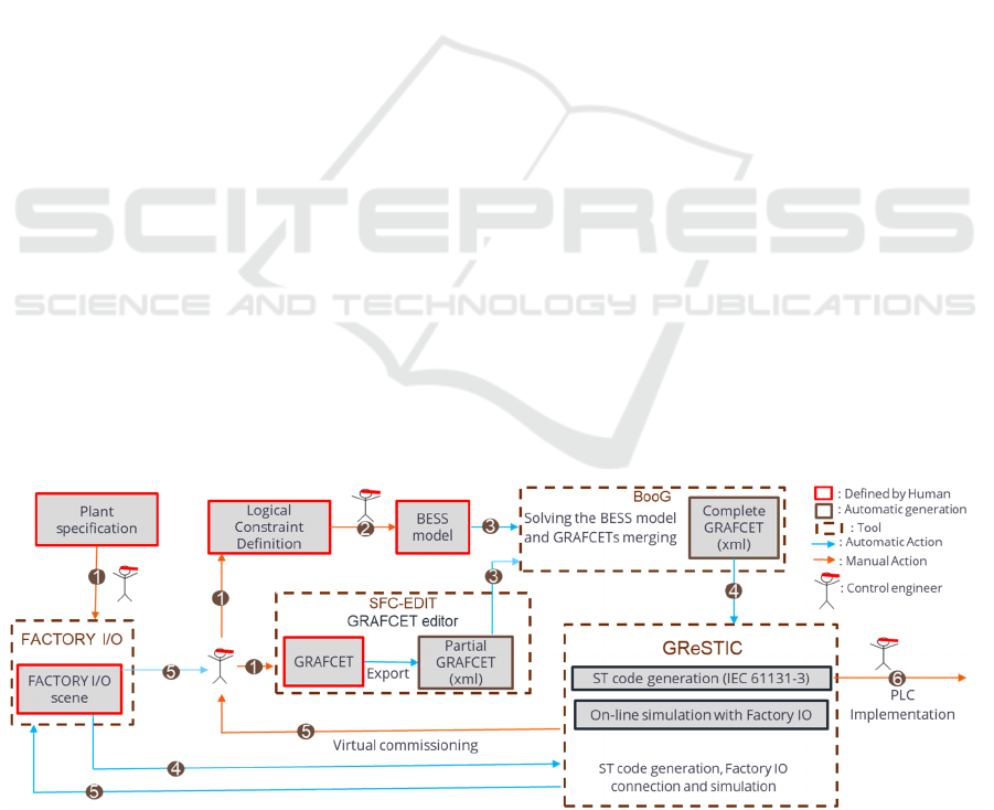
4.2 Workflow for Generating ST Code
that Can Be Executed by a PLC
The proposed workflow (see Figure 2) allows logic
control problems to be addressed by combining
intensional and extensional methods. It is
structured into six main steps:
1. Specification of the Logic Controller
The first step defines the controller’s behavior using
extensional and/or intensional approaches. The
extensional part is modeled in SFC-EDIT, which
edits and exports GRAFCETs in XML, while the
intensional part specifies logical constraints from
functional requirements and solves them
algebraically (Hietter, 2009). The controller then
operates on a physical or virtual system, whose
operational part (OP) is modeled, in our case, using
Factory I/O (Riera & Vigario, 2017).
2. Modeling in BESS Format.
The logical constraints are translated into a model
written in BESS (Boolean Equation System Solver)
format (Ranger, 2022).
3. Algebraic Synthesis and GRAFCETs Merging.
The BooG tool, developed in-house, uses the BESS
solver for algebraic synthesis. The solution is
converted into a GRAFCET (XML format) and
merged with fragments from the extensional
approach, producing a complete and consistent
GRAFCET model.
4. ST Code Generation.
The GReSTIC software, also developed in our
laboratory, generates ST (Structured Text) code for
the logic controller from the Factory I/O (Riera &
Vigario, 2017) scene and the complete GRAFCET
model in XML format.
5. Virtual Commissioning
GReSTIC includes a soft PLC for simulating the
controller and interacting in real time with Factory
I/O, enabling virtual commissioning to test and
validate the control logic before deployment.
6. Deployment on a Physical PLC
Once validated, the ST code can be deployed on a real
PLC, ensuring consistency between simulation and
operation.
Figure 2: Workflow for ST code generation from algebraic synthesis (AS) and GRAFCET.
From Algebraic Synthesis and GRAFCET to Logical Controller Design in ST Code (IEC 61131-3)
497
5 SOFTWARE TOOLS
5.1 GReSTIC Software
GReSTIC (GRAFCET to ST, Integration, and
Commissioning) is a code generator and simulator for
Structured Text (ST), based on GRAFCET
specifications, developed in the laboratory. GReSTIC
is a Windows application developed in C# using the
.NET Framework 4.8.
As input, it uses a GRAFCET specification
described in an open XML format. The tool used to
graphically represent GRAFCETs is called SFCEdit.
This editor was chosen because of its ability to export
to an open XML format and its compliance with the
standard (International Electrotechnical Commission,
2013b).
GReSTIC has a strong integration with the
Factory-I/O simulator, abstracting the configuration
of communication driver settings. The GRAFCETs
contained in the XML file are analyzed, and the
communication driver information from the Factory-
I/O scene is incorporated. PLC code in Structured
Text (ST) is then generated. This code can be either
simulated directly within the integrated simulator or
exported to various software targets.
5.2 BooG Software
BooG (Renard, 2024) is an application that enables
the transcription of the resulting unknown equations
from BESS into a format compatible with GReSTIC.
It is a Python-based application provided as an
executable with a graphical user interface to improve
user experience. It is configured by entering two
fields: one corresponding to the BESS file and the
other to the export from SFCEdit in XML format. The
insertion index allows placing the filter generated by
BESS at a specific location within the set of
GRAFCETs contained in the SFCEdit XML
specification file.
As input, the specification file to be solved by
BESS must be provided. Additionally, an optional file
exported from SFCEdit can be included. After BESS
solves the system of equations, the equations are
retrieved and transformed into GRAFCET format.
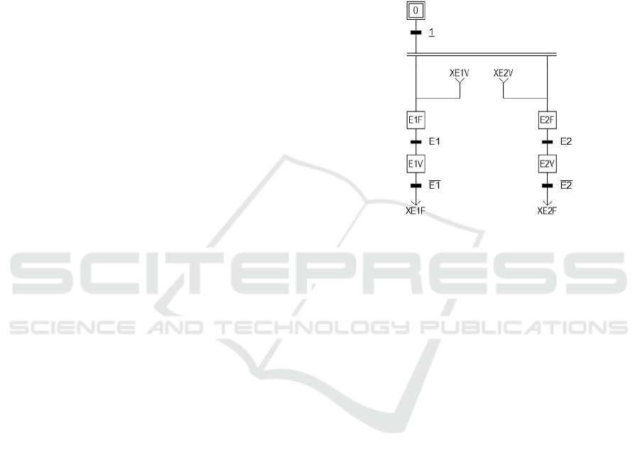
Figure 3 illustrates the GRAFCET model used to
integrate the equations produced by BESS (example
with two equations). For each equation returned in the
solution by BESS, two GRAFCET steps are created,
one representing the equation being true and the other
representing it being false. Two transitions allow
looping between the true and false states. These
transitions respectively correspond to the equation
and its negation. In this way, the equation is
represented in GRAFCET form. This step-based
representation makes it possible to position the
equations precisely within the program. In contrast,
representing equations as actions would imply that
they are calculated at the end of the cycle. The symbol
E1V corresponds to the symbol of the unknown
associated with the equation. Thus, as soon as the step
is evaluated, its value is already updated for the rest
of the ongoing cycle's calculations.
Figure 3: GRAFCET model generated by BooG.
The resulting GRAFCET is returned to the user.
If an SFCEdit file has been provided, the generated
GRAFCET is inserted into the set of GRAFCETs in
the SFCEdit file at the specified position.
6 CASE STUDY
We illustrate our approach to algebraic synthesis
using a system involving the crossing of two
conveyors (see Figure 4 from the Discrete Event
System (SED) 2023 school (Riera & Renard, 2024)).
Each flow is regulated by a traffic light (red or green),
and pallets must wait for a green light before crossing
the shared zone, which is made accessible by a
turntable. This example is a simple proof of concept
in order to demonstrate the proposed workflow.
Two sensors indicate the position of the turntable:
• TTLimit12: Turntable is in position 12
• TTLimit34: Turntable is in position 34
Pallets are autonomous—meaning they stop when
the light is red and proceed when it is green. This
behavior is implemented via a dedicated control
(described in GRAFCET, see Figure 5), which
manages the back-and-forth movement of the two
pallets. The intent to cross is represented by four
GRAFCET steps: XR12, XR21, XR34, and XR43.
ICINCO 2025 - 22nd International Conference on Informatics in Control, Automation and Robotics
498
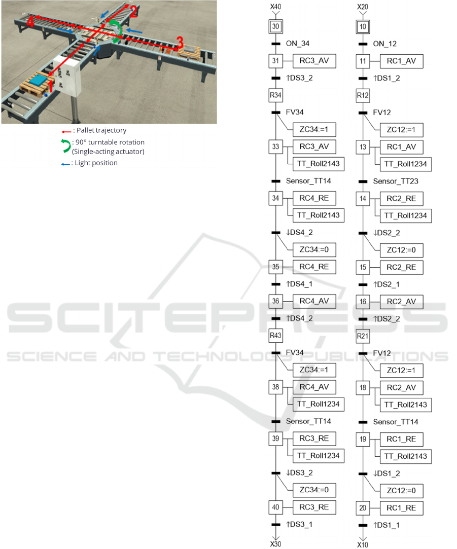
Figure 4: Case study system.
Two global variables (ZC12, ZC34) indicate the
presence of a pallet in the shared area. A user-
activated button determines the default position of the
turntable (ValDefaut).
Nine actuators must be controlled, including the
green/red traffic lights and the turntable actuator:
• Traffic lights: FV12, FR12, FV21, FR21,
FV34, FR34, FV43 and FR43
• TTTurn: Single-acting turntable rotation
(Active = position 12, Inactive = position
34)
The control objective is to synchronize the lights
and turntable to avoid collisions, while ensuring the
automatic return of the turntable to its default position
(ValDefaut = 0 corresponds to turntable position 34).
6.1 Bess Model Creation
In the Algebraic Synthesis (AS) formalism, the
problem is reduced to constraints from requirements
and assumptions, with a solution criterion usually
maximizing unknown variables.
For the case study, we defined fifteen requirement
constraints, three assumption constraints, and four
maximization constraints to ensure a unique solution
(see Figure 6). Currently, no method exists to
systematically derive the constraint set directly from
the requirements.
Figure 5: Pallets control GRAFCET.
From Algebraic Synthesis and GRAFCET to Logical Controller Design in ST Code (IEC 61131-3)
499

Figure 6: Extraction of the BESS constraint model for the
case study problem.
6.2 BooG Software Solving
We obtained this set of Boolean expressions (Figure
7
) using the BooG software to solve the BESS model
of the case study for each unknown variable
(intermediate and actuator variables) in terms of
known variables (sensors and GRAFCET states).
Then, by merging the BESS model solution with
the pallet control GRAFCET, we obtain a complete
GRAFCET, This complete GRAFCET is not
intended for human reading.
Figure 7: Algebraic Synthesis solution.
6.3 ST Code Generated from GReSTIC
Using GReSTIC, we generate ST code from the
complete GRAFCET and the Factory I/O scene. Its
PLC simulator interacts with Factory I/O, allowing us
to validate the constraints used in the model. The
solution for this case study is valid. A video
demonstrates the full workflow from the BESS model
to simulation: https://youtu.be/Q6IbG3DUudY
6.4 Case Study Conclusion
The workflow combines intensional (SA) and
extensional (GRAFCET) approaches for controller
synthesis. The BESS model from the intensional part
is automatically solved and merged with the
GRAFCET to generate ST code that can be used in an
API. We can simulate that ST code on the Factory I/O
scene to evaluate the validity of the model.
7 CONCLUSION AND OUTLOOK
This paper presented a workflow combining algebraic
synthesis with extensional modeling (GRAFCET) for
logic controller synthesis. Controller specifications
are defined via a BESS model and a GRAFCET
diagram. BooG software automatically solves the
BESS model and integrates it with the GRAFCET,
while GReSTIC software uses the combined
GRAFCET and a Factory I/O scene to generate ST
(*----------------Constraints------------------*)
(*Red light opposite of green light*)
FV12 = /(FR12); FV34 = /(FR34);
(*Can have green light in direction X if pallet in commo
n
zone (ZC) with direction X or if authorizing the pallet with
direction X to go in the common zone AND if the
Turntable is in the X position*)
FV12 <= (TTLimit12 . (AUT12 + ZC12));
FV34 <= (TTLimit34 . (AUT34 + ZC34));
(FV12 . FV34) = 0; (*Cannot have both green light*)
(*If a pallet is in the ZC with X direction then the X gree
n
light must be on*)
(ZC12 . /(FV12)) = 0; (ZC34 . /(FV34)) = 0;
(*The turntable turn (actuator) according to the directio
n
of the pallet in ZC or the authorized direction*)
(ZC12 + AUT12) <= TTTurn;
(ZC34 + AUT34) <= /(TTTurn);
(*Can have an authorization of a pallet in direction X if
a
pallet wants to cross the turntable in direction X AND i
f
there is not a pallet in ZC in the other direction AND if we
don’t authorize the pallet in the other direction to cross*)
AUT12 <= (((XR12 + XR21) . /(ZC34)) . /(AUT34));
AUT34 <= (((XR34 + XR43) . /(ZC12)) . /(AUT12));
(*The light value in a direction are the same*)
FV21 = FV12; FR21 = FR12;
FV43 = FV34; FR43 = FR34;
(*-----------------Assumptions---------------*)
(TTLimit34 . TTLimit12) = 0;(*Cannot have the turntable
in both position at the same time*)
(ZC12 . TTLimit34) + (ZC12 . /(TTLimit12)) + (ZC34 .
/(TTLimit34)) + (ZC34 . TTLimit12)) = 0; (*Necessary
hypothesis for coherence.*)
(*---------Maximization-----------*)
M0 : Maximal (*Maximize authorization of a pallet in the
34 direction*)
AUT34;
M1 : Maximal (*Maximize authorization of a pallet in the
12 direction*)
AUT12;
M2 : Maximal (*Maximize the green lights on*)
FV12 + FV34;
M3 : Maximal (*Maximize default position*)
TTTurn . ValDefaut +/TTTurn . /ValDefaut;
FV12 = ZC12+TT_Limit12.XR12./XR34./XR43
+TT_Limit12./XR34./XR43.XR21
FV34 = ZC34+TT_Limit34.XR34+TT_Limit34.XR43
FR12 = ZC34+TT_Limit34+/TT_Limit12+
/ZC12.XR34+/ZC12.XR43+/ZC12./XR12./XR21
FR34 = ZC12+/TT_Limit34+TT_Limit12
+/ZC34./XR34./XR43
FV21 = ZC12+TT_Limit12.XR12./XR34./XR43
+TT_Limit12./XR34./XR43.XR21
FV43 = ZC34+TT_Limit34.XR34+TT_Limit34.XR43
FR21 = ZC34+TT_Limit34+/TT_Limit12+/ZC12.XR34 +
/ZC12.XR43+/ZC12./XR12./XR21
FR43 = ZC12+/TT_Limit34+TT_Limit12
+/ZC34./XR34./XR43
TT_Turn = ZC12+/ZC34.XR12./XR34./XR43
+/ZC34./XR34./XR43.XR21
+/ZC34./XR34./XR43.ValDefaut
AUT12 = ZC12.XR12+ZC12.XR21
+/ZC34.XR12./XR34./XR43+/ZC34./XR34./XR43.XR21
AUT34 = /ZC12.XR34+/ZC12.XR43
ICINCO 2025 - 22nd International Conference on Informatics in Control, Automation and Robotics
500

code, which can then be implemented on a PLC and
simulated.
The current approach lacks a structured
representation, relying on variables and Boolean
constraints that are hard to interpret for new users..
Understanding the complete system based solely on
these constraints and variables can be challenging.
Since the BESS model uses problem-specific
constraints, adding new requirements often requires
major changes, limiting extensibility and
generalizability.
We argue that overcoming these limitations
requires a structured approach for constructing a
generic set of elements and structured constraints
with a generic language adapted to any logic
controller synthesis problem. This approach involves
a clear definition and application of various types of
constraints to the distinct components of the
controller synthesis problem.
ACKNOWLEDGEMENTS
This research was funded by the French National
Research Agency (ANR) under the Digital Twins for
Cyber-Physical Systems project (ANR-23- CE10-
0010-01). The authors would like to thank the ANR.
REFERENCES
Hietter, Y. (2009). Synthèse algébrique de lois de
commande pour les systèmes à évènements discrets
logiques. Phd. École normale supérieure de Cachan -
ENS Cachan.
IEC 60848, (2012). GRAFCET specification language for
sequential function charts. (3rd ed.).
John, K.-H., & Tiegelkamp, M. (2001). IEC 61131-3:
Programming Industrial Automation Systems.
Springer.
Jones, C. T. (1998). Programmable Logic Controllers: The
Complete Guide to the Technology. Brilliant-Training.
Koren, Y. (2010). The Global Manufacturing Revolution:
Product-Process-Business Integration and
Reconfigurable Systems. John Wiley & Sons.
Leroux, H. (2011) Algebraic Synthesis of Logical
Controllers with Optimization Criteria. ENS Cachan,
Cachan, France.
Leroux, H., & Roussel, J. -M. (2012) Algebraic synthesis
of logicalcontrollers with optimization criteria.
Proceedings of the 6th International Workshop on
Verification and Evaluation of Computer and
Communication Systems (VECOS ’12), pp. 103–114.
Marques-Silva, J., et al (2011). Boolean lexicographic
optimization: algorithms & applications. Annals of
Mathematics and Artificial Intelligence, pp. 317-343.
Peregrin, J. (2007). Extensional vs. Intensional Logic. In
Philosophy of Logic (pp. 913-942). Elsevier.
Rabin, O. M., & Scott, D. (1959). Finite Automata and
Their Decision Problems. IBM Journal of Research and
Development, pp. 114-125.
Ramadge, P. J., & Wonham, W. M. (1987). Supervisory
Control of a Class Of Discret Event Processes. SIAM
Journal on Control and Optimization, pp. 206-230.
Ranger, T., et al (2021). Manufacturing Tasks
Synchronization by Algebraic Synthesis. 4th IFAC
Conference on Embedded Systems, Computational
Intelligence and Telematics in Control CESCIT 2021,
pp. 226-231.
Ranger, T. (2022). Approche par synthèse algébrique et
filtre logique pour la commande des systèmes
manufacturiers cyber-physiques. Phd. Université de
Reims Champagne-Ardenne, Reims.
Renard, D., et al (2024). From Reinforcement Learning to
Reality: Generating Structured Text Logic Controller.
2024 10th International Conference on Control,
Decision and Information Technologies (CoDIT), pp.
1269-1274.
Riera, B., & Renard, D. (2024). École SED et plateforme de
formation en ligne : une dynamique pour la diffusion
des systèmes à événements discrets https://fad.univ-
lorraine.fr/pluginfile.php/158867/mod_label/intro/UT
L_CTRL_SA_Application.pdf
Riera, B., & Vigario, B. (2017). HOME I/O and FACTORY
I/O: a virtual house and a virtual plant for control
education. 20th IFAC World Congress, pp. 9144-9149.
Roussel, J.-M., & Lesage, J. (1996). Validation and
verification of grafcets using state machine.
Proceedings of IMACS-IEEE ”CESA'96”, pp. 758-764.
Roussel, J.-M., & Lesage, J.-J. (2012). Algebraic synthesis
of logical controllers despite inconsistencies in
specifications. IFAC Proceedings Volumes, pp. 307-
314.
Roussel, J.-M., & Lesage, J.-J. (2014). Design of Logic
Controllers Thanks to Symbolic Computation of
Simultaneously Asserted Boolean Equations.
Mathematical Problems in Engineering, pp. 1-15.
Schumacher, F., et al (2013). Tool support for an automatic
transformation of GRAFCET specifications into IEC
61131-3 control code. 2013 IEEE 18th Conference on
Emerging Technologies & Factory Automation
(ETFA).
Teng, S.-H., & Black, J. T. (1990). Cellular manufacturing
systems modeling: The Petri net approach. Journal of
Manufacturing Systems, pp. 45-54.
From Algebraic Synthesis and GRAFCET to Logical Controller Design in ST Code (IEC 61131-3)
501
