Towards Fully Onboard State Estimation and Trajectory Tracking for
UAVs with Suspended Payloads
Martin Jirou
ˇ
sek
a
, Tom
´
a
ˇ
s B
´
a
ˇ
ca
b
and Martin Saska
c
Department of Cybernetics, Faculty of Electrical Engineering, Czech Technical University in Prague, Prague, Czech
Republic
Keywords:
Unmanned Aerial Vehicle, Suspended Payload, Autonomous Aerial Transportation, Onboard Estimation,
Model Predictive Control.
Abstract:
This paper addresses the problem of tracking the position of a cable-suspended payload carried by an un-
manned aerial vehicle, with a focus on real-world deployment and minimal hardware requirements. In contrast
to many existing approaches that rely on motion-capture systems, additional onboard cameras, or instrumented
payloads, we propose a framework that uses only standard onboard sensors—specifically, real-time kinematic
global navigation satellite system measurements and data from the onboard inertial measurement unit—to es-
timate and control the payload’s position. The system models the full coupled dynamics of the aerial vehicle
and payload, and integrates a linear Kalman filter for state estimation, a model predictive contouring con-
trol planner, and an incremental model predictive controller. The control architecture is designed to remain
effective despite sensing limitations and estimation uncertainty. Extensive simulations demonstrate that the
proposed system achieves performance comparable to control based on ground-truth measurements, with only
minor degradation (< 6%). The system also shows strong robustness to variations in payload parameters. Field
experiments further validate the framework, confirming its practical applicability and reliable performance in
outdoor environments using only off-the-shelf aerial vehicle hardware.
1 INTRODUCTION
Unmanned aerial vehicles (UAVs) are playing an in-
creasingly vital role across a wide range of applica-
tions, from aerial mapping (Colomina and Molina,
2014), infrastructure inspection (Sikora et al., 2023),
and precision agriculture (Gode et al., 2024), to last-
mile delivery (Murray and Chu, 2015) and environ-
mental monitoring (C. et al., 2024). As their use be-
comes more widespread, there is a growing demand
for advanced control strategies that ensure reliable op-
eration in challenging, real-world conditions.
In this paper, we address the problem of track-
ing the position of a payload suspended from a UAV.
Our focus lies in enabling reliable deployment in field
conditions while minimizing hardware requirements.
We propose a solution that operates using only stan-
dard UAV hardware—specifically, an RTK GNSS re-
ceiver and the onboard sensors available in most flight
controllers (e.g., IMU, barometer, magnetometer...).
a
https://orcid.org/0009-0003-4552-9995
b
https://orcid.org/0000-0001-9649-8277
c
https://orcid.org/0000-0001-7106-3816
Based on these inputs, we estimate and control the
position of the suspended payload along a predefined
reference trajectory.
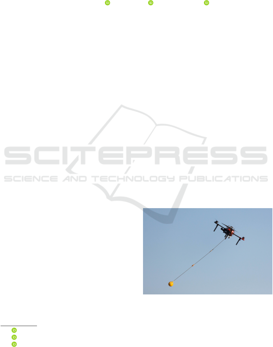
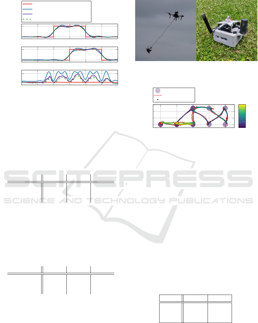
Figure 1: UAV carrying a cable suspended payload.
In many practical applications, it is the posi-
tion of the payload—rather than the UAV itself—that
must be accurately controlled. For example, in ag-
ile pickup-and-delivery tasks, the end of the cable can
reach the target before the UAV, exploiting the com-
128
Jiroušek, M., Bá
ˇ
ca, T. and Saska, M.
Towards Fully Onboard State Estimation and Trajectory Tracking for UAVs with Suspended Payloads.
DOI: 10.5220/0013789200003982
Paper published under CC license (CC BY-NC-ND 4.0)
In Proceedings of the 22nd International Conference on Informatics in Control, Automation and Robotics (ICINCO 2025) - Volume 2, pages 128-138
ISBN: 978-989-758-770-2; ISSN: 2184-2809
Proceedings Copyright © 2025 by SCITEPRESS – Science and Technology Publications, Lda.

plex system dynamics. Similarly, in applications such
as deploying sensors into hazardous or constrained
environments, contacting surfaces with the payload,
or precise mechanical interaction with the environ-
ment, controlling the payload’s position is of primary
importance. Reducing the hardware and instrumenta-
tion requirements is key to simplifying deployment
and lowering system cost—motivating our reliance
solely on RTK GNSS and standard flight-controller
sensors.
This problem presents significant challenges. The
UAV-payload system is highly underactuated and ex-
hibits complex, nonlinear coupled dynamics. Com-
pounding the difficulty, the position and orientation
of the payload are not directly measured in our setup.
Existing state-of-the-art solutions either rely on adap-
tive controllers that treat the payload dynamics as dis-
turbances (Li et al., 2023), (Wang et al., 2024), or on
perception-constrained control frameworks that use
downward-facing cameras to track the payload (Li
et al., 2021), (Recalde et al., 2025), (Sarvaiya et al.,
2025). However, vision-based approaches introduce
substantial complexity, cost, and sensitivity to envi-
ronmental conditions, as well as constraints on main-
taining payload visibility within the camera’s field of
view. A key limitation across many prior works is the
lack of robust, fully onboard estimation tightly cou-
pled with control.
We address this gap by designing and validating
a lightweight, onboard-only state estimation and con-
trol framework capable of real-world payload track-
ing using generic UAV hardware. Our solution con-
sists of a linear Kalman filter (LKF)-based estimator,
an incremental model predictive controller (MPC),
and a motion-planning component based on model
predictive contouring control (MPCC). The incre-
mental MPC formulation is inherently robust to zero-
mean noise, which allows us to tune the estimator
for low bias at the cost of tolerable noise. Mean-
while, the MPCC planner enables smooth transitions
between reference waypoints and allows flexible tra-
jectory shaping.
Experimental results show that the proposed sys-
tem performs comparably to an idealized setup us-
ing ground-truth payload position, with only marginal
performance degradation. The framework also
demonstrates robustness to variations in payload pa-
rameters and has been successfully deployed in real-
world outdoor environments, achieving results con-
sistent with simulation. These findings highlight the
viability of practical, low-cost UAV-based suspended
payload tracking using only standard onboard sen-
sors.
2 RELATED WORK
Early research on UAVs with suspended payloads pri-
marily focused on generating swing-free trajectories
and stabilizing hover under load. A pioneering con-
tribution (Palunko et al., 2012) demonstrated offline
planning of swing-free maneuvers using dynamic
programming and input-shaping techniques. Subse-
quent work (Faust et al., 2013) applied reinforcement
learning to synthesize swing-minimized trajectories
under uncertain dynamics. Later approaches, such
as (Sreenath et al., 2013), leveraged differential flat-
ness and geometric control to enable simultaneous
tracking of both UAV and payload trajectories. The
field has since expanded to include hybrid control
frameworks (Wang et al., 2024), disturbance-robust
planning (Li et al., 2023), and cooperative multi-robot
transportation strategies (Zhang et al., 2023). How-
ever, accurate payload position tracking—particularly
under onboard-only sensing—remains an open chal-
lenge.
Many works have focused exclusively on planning
and control algorithms, typically evaluated in simu-
lation or under motion-capture conditions. For in-
stance, (Li et al., 2023) proposed a real-time NMPC
framework with whole-body safety guarantees, but
evaluated it only in simulation or controlled labora-
tory environments. In (Zhang et al., 2023), cooper-
ative multi-UAV planning using insetting-formation
methods was explored, though it relied heavily on ex-
ternal sensing and did not address onboard-only exe-
cution. Similarly, (Tang and Kumar, 2015) presented
MIQP-based trajectory planning with hybrid dynam-
ics and obstacle avoidance, assuming accurate state
feedback. Overall, realistic onboard state estimation
has often been abstracted or oversimplified in these
control-centric studies.
A prominent line of research aims at estimating
payload state—typically angles or position—to en-
able payload-aware control. Early methods employed
inertial measurements or encoder-based observers to
infer payload swing online, but required dedicated
sensors (Rego and Raffo, 2016). More recent ap-
proaches have leveraged perception-driven estima-
tion. For example, PCMPC (Li et al., 2021) proposed
a perception-constrained MPC that fuses monocular
camera and IMU data to estimate the cable direc-
tion and payload dynamics. Later, hybrid perception-
aware frameworks such as HPA-MPC (Sarvaiya et al.,
2025) and ES-HPC-MPC (Recalde et al., 2025) in-
troduced advanced control and estimation strategies
capable of handling slack-taut transitions, while en-
forcing visibility constraints via onboard cameras.
Although these perception-enhanced MPC methods
Towards Fully Onboard State Estimation and Trajectory Tracking for UAVs with Suspended Payloads
129

demonstrate high performance, they require reliable
visual feedback and incur significant computational
overhead. In contrast, fully onboard estimation us-
ing only standard UAV sensors—such as the flight
controller IMU and RTK GNSS—is rarely addressed,
leaving a gap in lightweight, deployable solutions for
field-ready platforms.
To the best of our knowledge, no prior work has
demonstrated robust payload position tracking and
control in fully outdoor conditions using only GNSS
(specifically RTK) and standard flight-controller sen-
sors—without relying on motion capture, external
cameras, or payload instrumentation. Our work
addresses this gap by designing and validating a
lightweight, onboard-only state estimation and MPC
framework capable of tracking suspended payloads
in real-world outdoor settings using standard UAV
hardware. This enables practical deployment across a
broad range of platforms and outdoor environments.
3 MATHEMATICAL MODEL
The modeling of aerial systems transporting sus-
pended payloads is a well-established problem in
aerial robotics, with one of the most influential for-
mulations introduced in (Palunko et al., 2012). Their
model, based on a Lagrangian derivation under the as-
sumption of a taut, massless cable, captures the cou-
pled motion between the unmanned aerial vehicle and
the payload with sufficient fidelity for control design,
while remaining analytically tractable. In this work,
we adopt the core structure of Palunko’s model and
extend it to account for aerodynamic damping effects
on both the aerial vehicle and the payload. The inclu-
sion of linear air-drag terms for each body provides a
more realistic description of energy dissipation in out-
door environments, improving the model’s suitability
for real-time state estimation and control under realis-
tic conditions. This mid-level formulation maintains
a balance between physical fidelity and computational
efficiency, enabling onboard implementation without
sacrificing robustness to unmodeled effects.
3.1 Assumptions
To ensure analytical tractability without significantly
compromising realism, several simplifying assump-
tions are introduced. The cable linking the UAV and
the payload is modeled as massless and always taut,
with attachment points located precisely at the centers
of mass (CoG) of both bodies. This eliminates any
torque contributions or additional inertial effects due
to the cable. The payload is treated as a rigid body
of known mass m
l
and suspended at a fixed length
l. Aerodynamic drag is included for both the UAV
and payload, modeled as linear with respect to transla-
tional velocity. The payload is further assumed to ex-
hibit symmetric aerodynamic characteristics, exclud-
ing rotational drag and shape-induced effects. Fric-
tion at the cable connection is neglected, thereby al-
lowing the payload to rotate freely about the sus-
pension point. Environmental disturbances such as
wind are completely omitted to improve tracktability
of the model. These modeling choices align with es-
tablished literature (Palunko et al., 2012) and yield a
manageable yet sufficiently expressive dynamic for-
mulation.
3.2 System Description
W
ˆw
x
ˆw
y
ˆw
z
ˆ
b
x
ˆ
b
y
ˆ
b
z
B
s
uav
θ
l
φ
l
L
ˆ
l
x
ˆ
l
y
ˆ
l
z
Figure 2: Coordinate systems and generalized coordinates
of the UAV-payload system.
The system configuration is described using three
right-handed Cartesian coordinate frames, as illus-
trated in Fig. 2. The world frame W is an inertial
frame fixed to the Earth, with
ˆ
w
z
oriented upward.
The body frame B is rigidly attached to the UAV, cen-
tered at its CoG, with
ˆ
b
z
aligned with the thrust direc-
tion. The load frame L is centered at the payload’s
CoG, with
ˆ
l
z
aligned along the cable, and
ˆ
l
x
,
ˆ
l
y
paral-
lel to the corresponding body frame axes.
The UAV’s generalized coordinates in the world
frame are defined by:
q
uav
=
x y z θ φ ψ
⊺
, (1)
where s
uav
=
x y z
⊺
denotes the UAV’s posi-
tion, and Γ =
θ φ ψ
⊺
corresponds to its orien-
tation, expressed via Tait-Bryan angles. The rotation
from body to world frame is given by:
R
B→W
(φ,θ,ψ) = R
z
(ψ)R
y
(θ)R
x
(φ). (2)
Under the assumption of a taut cable, the pay-
load’s relative position is parameterized by two an-
ICINCO 2025 - 22nd International Conference on Informatics in Control, Automation and Robotics
130

gles:
q
l
=
θ
l
φ
l
⊺
, (3)
which define the load-to-world rotation matrix as:
R
L→W
(φ
l
,θ
l
) = R
x
(φ
l
)R
y
(θ
l
). (4)
Using this formulation, the payload’s absolute posi-
tion becomes:
s
l
= R
L→W
0 0 −l
⊺
+ s
uav
. (5)
3.3 Equations of Motion
Since the system’s potential and kinetic energies do
not depend on UAV attitude, the dynamics are formu-
lated using the reduced generalized coordinate vector:
q =
s
uav
q
l
⊺
. (6)
The Lagrangian is constructed in the standard form:
L (q,
˙
q) = T (
˙
q) − V (q), (7)
where the potential energy is expressed as:
V (q) = g
0 0 1
⊺
(m
uav
s
uav
+ m
l
s
l
), (8)
and the kinetic energy is given by:
T (
˙
q) =
1
2
m
uav
||
˙
s
uav
||
2
+ m
l
||
˙
s
l
||
2
. (9)
The conservative force in the system originates
from UAV thrust, modeled as:
f
con
(Γ,F) =
R
B→W
(Γ)
0
0
0
F
, (10)
where F denotes the total collective thrust.
Aerodynamic drag represents the primary dissipa-
tive force and is incorporated as follows. The payload
drag, projected onto angular coordinates, is modeled
by:
f
l
dis
(
˙
q,q) = −d
l
1 0 0
0 −1 0
R
−1
L→W
(θ
l
,φ
l
)
˙
s
W
l
,
(11)
while the radial drag component acts on the UAV as:
f
uav
dis
(
˙
q,q) = −d
uav
˙
s
uav
−d
l
R
L→W
(θ
l
,φ
l
)
0 0 0
0 0 0
0 0 1
R
−1
L→W
(θ
l
,φ
l
)
˙
s
W
l
.
(12)
The complete expression for the dissipative force be-
comes:
f
dis
(
˙
q,q) =
f
uav
dis
f
l
dis
⊺
= −D(φ
l
,θ
l
)
˙
q. (13)
Combining these elements and applying the Eu-
ler–Lagrange formalism yields the governing equa-
tions of motion:
M(q)
¨
q + (C(
˙
q,q) + D(q))
˙
q + g(q) = f
con
(Γ,F).
(14)
3.4 Flight Controller Model
The UAV’s onboard flight controller (FCU) is ab-
stracted as a set of decoupled first-order systems
corresponding to each actuation channel. It tracks
reference inputs u via internal state variables x
a
=
θ φ ψ F
⊺
, governed by the following dy-
namics:
˙
x
a
= A
a
x
a
+ B
a
u, (15)
where A
a
and B
a
are diagonal matrices given by:
A
a
= diag
−
1
τ
1
,. .. ,−
1
τ
4
,
B
a
= diag
K
1
τ
1
,. .. ,
K
4
τ
4
,
(16)
with τ
i
and K
i
denoting the time constants and gains,
respectively, for each control channel.
3.5 State Space Model
The full nonlinear model, incorporating both physical
dynamics and the flight controller, is expressed as:
˙
q = ν,
˙
ν= −M
−1
(q)
(C(ν, q)+D(q)) ν+g(q)−f
con
(x
a
)
,
˙
x
a
= A
a
x
a
+ B
a
u.
(17)
It is noted that the mass matrix M becomes singular
at θ
l
=
π
2
, imposing a constraint on the domain of ex-
plicit solutions.
For the purposes of control and estimation de-
sign, the system is linearized about the hover equi-
librium with a motionless payload: θ
l
= φ
l
= 0 rad,
˙
θ
l
=
˙
φ
l
= 0 rads
−1
. The resulting linear time-invariant
(LTI) model is:
˙
x = Ax + Bu, (18)
where the state vector is composed as:
x =
q ν x
a
⊺
. (19)
4 CONTROL FRAMEWORK
The control framework consists of three components:
a state estimator, a tracking controller, and a trajec-
tory planner, as shown in Fig. 3. The state estimator
reconstructs the full system state, including unmea-
sured variables such as the payload position, using
UAV position and attitude measurements in conjunc-
tion with the system model introduced in Section 3.
Towards Fully Onboard State Estimation and Trajectory Tracking for UAVs with Suspended Payloads
131
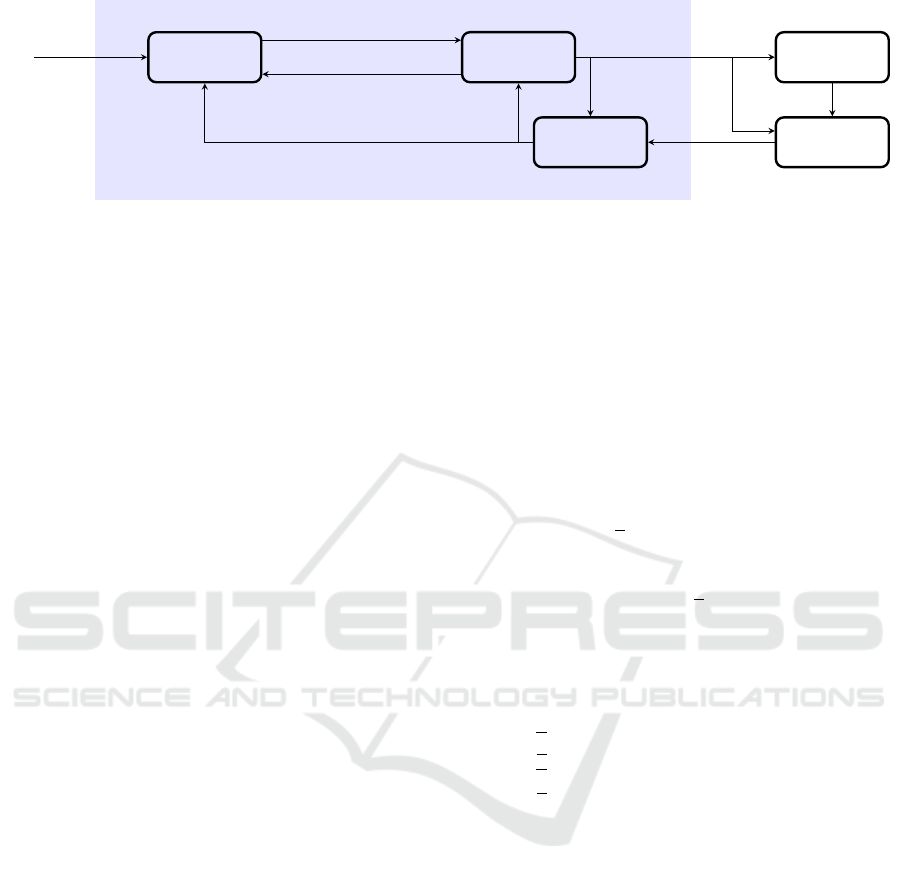
Flight
Controller
MPC
Controller
MPCC
Planner
LKF
Estimator
RTK
Estimator
UAV’s position
and attitude
state estimate
attitude commands
target trajectory
optimized trajectory
predicted initial condition
Figure 3: Architecture of the control framework. Blue block represents the proposed solution.
The tracking controller computes UAV attitude com-
mands that ensure the payload tracks a desired trajec-
tory by solving a constrained optimal control problem
in a receding horizon fashion. Finally, the trajectory
planner generates smooth, dynamically feasible refer-
ence trajectories online from sparse target states using
temporally weighted optimization.
These components operate at different rates to en-
sure computational efficiency: the estimator and con-
troller run at 100 Hz, while the trajectory planner exe-
cutes at 1 Hz, enabling long-horizon planning without
compromising real-time control performance.
4.1 State Estimator
We assume the UAV’s position is measured via RTK
GNSS, while its attitude is provided by the onboard
flight controller. Rather than relying on raw mea-
surements, we employ the RTK estimator from the
MRS UAV System (Baca et al., 2021), which provides
built-in health checks and outlier rejection to ensure
robust operation under field conditions.
To incorporate these measurements, the linear
state-space model from equation (18) is augmented
with a measurement model:
y = Cx =
I
3
0
3×7
0
3×3
0
3×1
0
3×3
0
3×7
I
3
0
3×1
x, (20)
where I
3
is the 3× 3 identity matrix and 0
a×b
denotes
an a × b zero matrix.
The estimator is implemented as a Linear Kalman
Filter (LKF) (Kalman, 1960) with empirically tuned
noise covariances Q and R, which balance smooth-
ness and responsiveness (values listed in Table 7).
To account for variability in control loop tim-
ing—caused primarily by the onboard online opti-
mization—the estimator employs forward Euler dis-
cretization with the current time step:
¯
A(d t) = I + dtA,
¯
B(d t) = dtB, (21)
ensuring consistent and time-accurate state propaga-
tion even when the loop interval varies.
4.2 Tracking Controller
The tracking controller generates UAV attitude com-
mands to track reference trajectories while account-
ing for constraints and dynamic limitations. It is for-
mulated as a constrained optimal control problem and
solved using Model Predictive Control (MPC) based
on the linearized system dynamics.
The optimization problem is posed as a quadratic
program (QP) with soft constraints:
min
˜
x
t
,...,
˜
x
t+N
˜
u
t
,...,
˜
u
t+N−1
s
t
,...,s
t+N
t+N
∑
n=t
1
2
˜
x
n
˜
u
n
1
⊺
Q
n
0 q
n
0 R
n
0
q
⊺
n
0 0
˜
x
n
˜
u
n
1
+
1
2
s
l
n
s
u
n
⊺
Z
l
n
0
0 Z
u
n
s
l
n
s
u
n
,
(22)
s.t.
˜
x
n+1
=
˜
A
n
˜
x
n
+
˜
B
n
˜
u
n
, n = t, .. .,t + N − 1,
˜
u
n
˜
x
n
≤
˜
u
n
˜
x
n
+ s
l
n
, n = t, .. .,t + N,
˜
u
n
˜
x
n
≥
˜
u
n
˜
x
n
+ s
u
n
, n = t, .. .,t + N.
(23)
To gain finer control over the control actions and
allow penalization of their rate, we adopt an incre-
mental model formulation introduced in (Qin and
Badgwell, 2003):
x
n+1
u
n+1
=
A B
0 I
x
n
u
n
+
B
I
∆u
n
. (24)
This formulation helps prevent the propagation of
noise from the state estimate to the control action and
introduces robustness against estimation errors.
The payload position is estimated from the system
state using a linearized form of Equation (5), includ-
ing control inputs:
˜
y
n
=
s
uav,n
+ l
−θ
l,n
φ
l,n
−1
u
n
=
˜
C
˜
x
n
1
. (25)
ICINCO 2025 - 22nd International Conference on Informatics in Control, Automation and Robotics
132
Deviation from the reference is penalized through:
Q
n
=
˜
C
⊺
diag(p
s
l
,p
u
)
˜
C, R
n
= diag(p
∆u
), (26)
with values specified in Table 7.
Slack variables ensure feasibility under noise or
disturbances, and the reference trajectory is intro-
duced via a linear state term:
q
n
=
x
d
n
⊺
Q
n
. (27)
The only states constrained in the optimization are
translational velocity (per-axis) and the UAV’s atti-
tude. The optimization problem is solved by the
HPIPM solver (Frison and Diehl, 2020) using partial
condensation (Axehill, 2015).
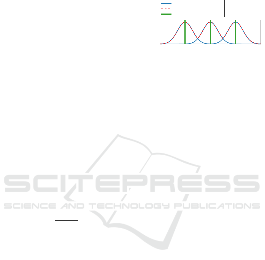
4.3 Trajectory Planner
The trajectory planner generates a dynamically feasi-
ble reference trajectory from target states using long-
horizon optimization, complementing the fast con-
troller operating at shorter time scales.
It solves an optimization problem structurally sim-
ilar to the controller’s formulation in (22), (23),
but adopts the Model Predictive Contouring Con-
trol (MPCC) paradigm introduced in (Romero et al.,
2022). The key difference lies in the time-varying
weighting matrix Q
i
applied along the planning hori-
zon:
Q
i
= ω
i
Q, i = 0,. .. ,N, (28)
where
ω
i
= max
k=1,...,M
exp
−
(t
r,k
−t
i
)
2
2σ
2
!
, i = 0,. .. ,N.
(29)
Here, t
r,k
denotes the timestamp of the k-th state in the
reference trajectory (consisting of M states), and t
i
is
the timestamp of the i-th step in the planning horizon.
The parameter σ controls the spread of the Gaussian
kernels used for weighting.
This temporal weighting approach allows the
planner to gradually transition between sparse refer-
ence points while maintaining smoothness and fea-
sibility. For large values of σ, the weights vary
slowly, encouraging adherence to the reference tra-
jectory throughout the horizon. Conversely, small σ
values lead to sharp peaks in the weighting, guiding
the system to closely match specific reference states
while allowing flexibility in between. The specific
value of σ used is provided in Table 7.
A limitation of long-horizon MPC planners is that
significant computation time may cause part of the
computed trajectory to become outdated before it is
applied. To mitigate this, the planner uses a predicted
system state at time t + t
plan
as its initial condition,
0 2 4 6 8
0
0.5
1
t [s]
ω [-]
Individual Gaussians
Weight
Timestamps of target states
Figure 4: Illustration of the Gaussian weighting function ω
i
along the planning horizon, centered at reference times t
r,k
.
where t
plan
is an estimate of the planner’s execution
time. This predicted state is available from the con-
troller’s internal MPC prediction and ensures tempo-
ral alignment between planning and control.
4.4 Limitations
The proposed control framework assumes a constant
UAV heading, as the payload-induced disturbances
are modeled in the world coordinate frame and the
system dynamics are linearized around a fixed head-
ing. Another limitation is the assumption that the
cable remains taut throughout the flight. Addition-
ally, the framework requires prior knowledge of the
payload’s parameters, such as mass and rope length.
The current implementation is not adaptive and relies
on these parameters being known and fixed. How-
ever, we consider these limitations to be acceptable
in many practical scenarios. If necessary, they could
be addressed through more complex adaptive, hybrid
and nonlinear methods, albeit at the cost of increased
computational demands.
5 VERIFICATION
This section verifies the full control pipeline using the
proposed metrics in both simulation and real-world
experiments. While the system is capable of track-
ing densely sampled reference trajectories, such tra-
jectories offer limited freedom for planning. In con-
trast, sparser trajectories allow for more planning op-
timizations and, when executed at higher speeds, bet-
ter expose the dynamic properties of the suspended
payload.
For instance, a slowly moving, densely sampled
reference trajectory can be accurately followed using
a conventional UAV position controller with a fixed
vertical offset corresponding to the cable length. In
such cases, the payload remains nearly stationary, and
swing angles θ
l
and φ
l
are negligible. Consequently,
the strengths and limitations of the proposed control
Towards Fully Onboard State Estimation and Trajectory Tracking for UAVs with Suspended Payloads
133
framework are most apparent when tracking agile,
sparse trajectories.
5.1 Methodology
Tracking errors on sparse reference trajectories are of-
ten difficult to interpret due to their potential inclusion
of discontinuities or infeasible transitions. As such,
absolute RMSE values can vary significantly depend-
ing on the chosen waypoint discretization.
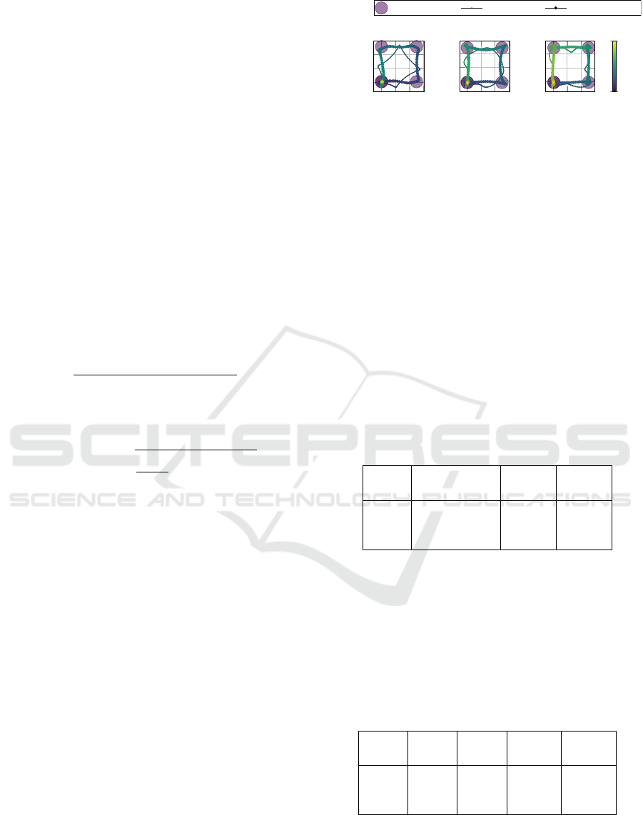
To establish a fair baseline, we introduce an open-
loop (OL) planner, which solves the same MPCC
problem (refer to Section 4.3) across the entire sparse
reference to generate a dynamically feasible trajec-
tory. These pre-planned OL trajectories, shown in
Fig. 5, serve as an idealized benchmark against which
closed-loop performance can be measured.
We evaluate the full closed-loop sys-
tem—including onboard estimation and MPC
tracking—against this baseline using the relative
RMSE degradation:
∆
RMSE
=
RMSE(x
exec
) − RMSE(x
OL
)
RMSE(x
OL
)
× 100%,
(30)
where RMSE(x) is computed over a trajectory x con-
sisting of states s
0
,. .. ,s
N
as:
RMSE(x) =
s
1
N + 1
N
∑
n=0
∥
s
ref
n
− s
n
∥
2
,
using zero-order hold to define a reference state s
ref
n
at
step n.
The metric ∆
RMSE
captures how much tracking
performance deteriorates compared to the ideal OL
plan. Increased degradation indicates effects of esti-
mation noise, limited prediction horizons, and model
mismatch. We report ∆
RMSE
across varying trajectory
speeds and payload parameters to assess robustness.
Two reference trajectories are used for evaluation:
a square trajectory and a complex, custom-designed
one. Both are composed of 3D waypoints with uni-
form temporal spacing defined by a time step dt.
The square trajectory consists of alternating 5 m
steps along the x and y axes, forming orthogonal seg-
ments to evaluate step response and speed sensitivity
(Fig. 5). The complex trajectory includes changes in
altitude, direction, and spacing, designed to challenge
the controller with dynamically rich behavior (visual-
ized in Fig. 8).
5.2 Simulation
Simulations were performed using the high-fidelity
Gazebo environment and the MRS UAV System,
0 2 4 6
0
2
4
x [m]
y [m]
dt = 1.5 s
payload waypoints
UAV trajectory
payload trajectory
0 2 4 6
0
2
4
x [m]
y [m]
dt = 2.0 s
0 2 4
0
2
4
x [m]
y [m]
dt = 2.5 s
0
15
Time [s]
Figure 5: Open-loop planned trajectories for the square sce-
nario, shown at different reference speeds.
known for accurate sim-to-real transfer (Baca et al.,
2021). The payload is modeled as a chain of 10 rigid
links connected via spherical joints. We analyze per-
formance in terms of both trajectory speed and pay-
load parameters.
5.2.1 Effect of Trajectory Speed
Simulations on the square trajectory were conducted
at different speeds by varying the time step dt ∈
{1.5,2.0, 2.5} s. Results in Table 1 confirm that faster
execution increases RMSE, as expected. For d t =
2.5 s, the tracking error nearly matches that of the OL
baseline, while for dt = 1.5 s, the degradation remains
below 40%.
Table 1: Tracking RMSE degradation on square trajectory
with varying speed (l = 2m, m
l
= 1.5 kg).
RMSE(x
OL
) ∆
gt
RMSE
∆
RMSE
dt [s] [m] [%] [%]
1.5 0.873 32.45 38.03
2.0 0.864 16.12 18.79
2.5 0.874 1.33 4.61
Table 2 shows estimation RMSEs for the swing
angles and angular velocities. Estimation accuracy re-
mains stable and correlates with trajectory excitation
levels. Minimal difference between using ground-
truth and estimated states (< 6%) demonstrates the
estimator’s reliability. Figure 6 illustrates a represen-
tative tracking result.
Table 2: Estimation RMSE for square trajectory with vary-
ing speed (l = 2 m, m
l
= 1.5 kg).
θ
l
φ
l
˙
θ
l
˙
φ
l
dt [s] [rad] [rad] [rad/s] [rad/s]
1.5 0.085 0.097 0.167 0.202
2.0 0.049 0.052 0.115 0.126
2.5 0.075 0.095 0.149 0.203
5.2.2 Effect of Payload Parameters
To evaluate robustness against different payload con-
figurations, we simulate the complex trajectory for
ICINCO 2025 - 22nd International Conference on Informatics in Control, Automation and Robotics
134
0 2 4 6 8 10 12
0
5
x [m]
target trajectory
reference feasible trajectory
estimate of executed trajectory
ground-truth executed trajectory
0 2 4 6 8 10 12
0
5
y [m]
0 2 4 6 8 10 12
0
0.5
t [s]
z [m]
Figure 6: Closed-loop tracking on square trajectory (dt =
2s).
varying cable lengths and masses (Table 3).
Estimation RMSE decreases with increasing
mass, likely due to stronger excitation improving ob-
servability. Cable length has a minor effect, though
longer cables show slightly increased errors.
Table 3: Estimation RMSE [rad] of payload angles across
parameters (dt = 2 s).
l = 1 m l = 2 m l = 3 m
m
l
= 0.5 kg 0.201 0.145 0.186
m
l
= 1.0 kg 0.190 0.146 0.168
m
l
= 1.5 kg 0.179 0.141 0.163
Tracking degradation (Table 4) generally de-
creases with payload mass. However, results reveal
that l = 2 m consistently leads to higher errors, sug-
gesting that dynamic compatibility between the pay-
load and trajectory may outweigh pure underactuation
effects.
Table 4: Relative tracking RMSE degradation [%] across
parameters (dt = 2 s).
l = 1 m l = 2 m l = 3 m
m
l
= 0.5 kg 4.50 5.76 5.66
m
l
= 1.0 kg 2.29 4.97 3.37
m
l
= 1.5 kg 1.53 4.26 1.62
5.3 Real-World Deployment
We deployed the proposed control pipeline on a
Tarot T650 UAV platform equipped with an on-
board Intel NUC computer, a Pixhawk 4 flight
controller, and an Emlid Reach M2 RTK GNSS
module to obtain global position measurements
(Fig. 7(a)). A video of the real-world experiment
is available at https://mrs.fel.cvut.cz/papers/
(a) Photo from experiment
(b) Payload with RTK GNSS
Figure 7: Experimental hardware used in the field deploy-
ment.
−5 0 5 10 15
0
2
4
6
x [m]
y [m]
payload waypoints
payload estimate
payload ground-truth
0
10
20
30
Time [s]
Figure 8: Executed trajectory during the real-world experi-
ment.
uav-with-cable-suspended-payload. The pay-
load consisted of a second Intel NUC, also equipped
with an identical RTK GNSS receiver (Fig. 7(b)), en-
abling direct ground-truth measurements of the pay-
load’s 3D position. The payload mass was 1.5 kg and
it was suspended using a 2.0 m cable. To ensure accu-
rate data synchronization between the UAV and the
payload computers, the two NUCs were physically
connected via an Ethernet cable.
The payload was tasked with following a com-
plex reference trajectory (see Fig. 8), discretized with
dt = 3 s. To assess the quality of the payload angle
estimation, we compared the estimated angles (θ
l
,φ
l
)
with ground-truth angles reconstructed directly from
the RTK GNSS position measurements. Fig. 9 illus-
trates the comparison across the full trajectory, while
Table 5 summarizes estimation statistics for each an-
gle.
Table 5: Estimation accuracy on real-world trajectory
θ
l
[rad] φ
l
[rad]
RMSE 0.178 0.078
STD 0.172 0.077
Bias 0.046 0.012
Estimation error is slightly higher in θ
l
, which cor-
responds to the direction of stronger excitation due to
trajectory design. Importantly, both estimated angles
exhibit very low bias relative to their standard devia-
tion, indicating that the error is primarily due to zero-
Towards Fully Onboard State Estimation and Trajectory Tracking for UAVs with Suspended Payloads
135
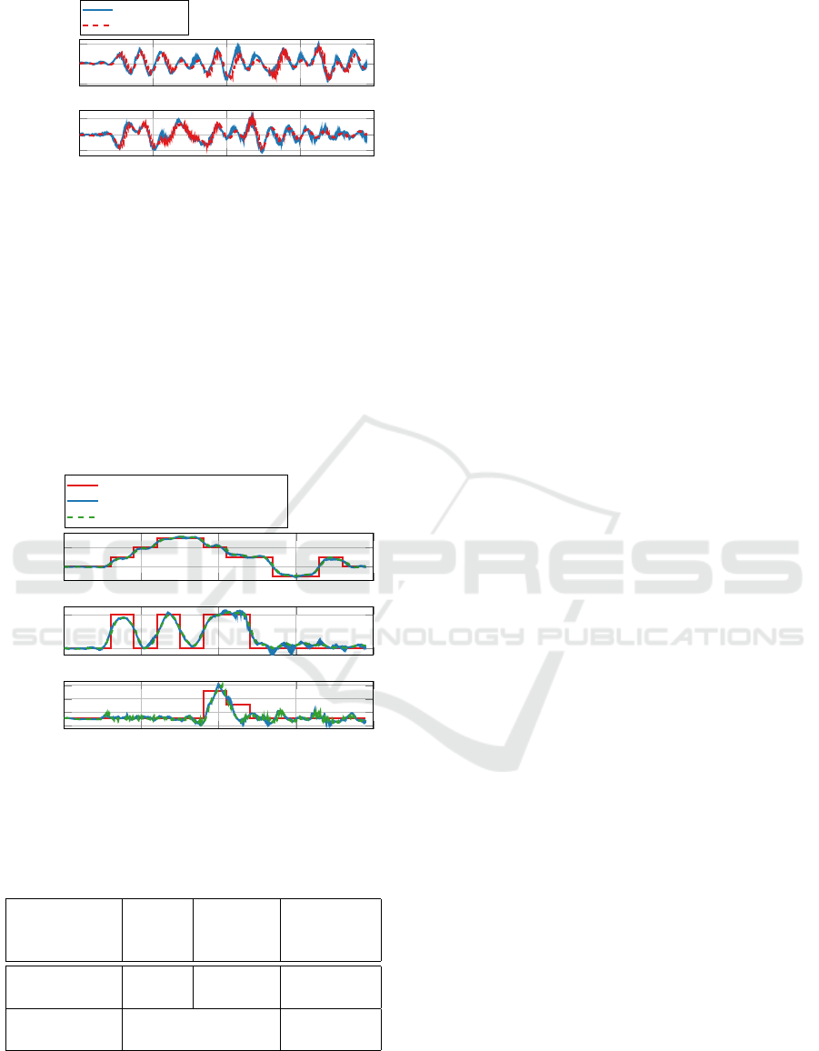
0 10 20 30 40
−1
0
1
θ
l
[rad]
estimate
ground-truth
0 10 20 30 40
−0.5
0
0.5
t [s]
ϕ
l
[rad]
Figure 9: Comparison of estimated and ground-truth pay-
load angles.
mean noise rather than modeling inaccuracies. This
supports the validity of the dynamic model introduced
in Section 3.
Using these state estimates, the UAV successfully
tracked the desired trajectory. Fig. 10 shows the track-
ing performance over the flight. Quantitative results
are given in Table 6, which also presents simulation
performance on the same trajectory to allow a sim-to-
real comparison.
0 10 20 30 40
0
10
x [m]
target trajectory
estimate of executed trajectory
ground-truth executed trajectory
0 10 20 30 40
0
5
y [m]
0 10 20 30 40
5
6
7
8
t [s]
z [m]
Figure 10: Trajectory tracking performance in real-world
flight.
Table 6: Real-world vs. simulation performance compari-
son.
Environment
∆
RMSE
Tracking
RMSE
[m]
Estimation
RMSE
[rad]
Simulation 1.36 1.563 0.134
Real-world 7.26 1.654 0.194
Sim-to-real
gap
+6% +45%
While estimation RMSE increases by 45% in the
real-world setting, tracking RMSE increases by only
6%. This highlights the robustness of the MPC
controller to noisy state estimates. The estimator’s
low bias ensures that tracking errors do not accu-
mulate, while the controller’s incremental structure
effectively filters out high-frequency estimation er-
ror. These results demonstrate that the full control
pipeline—from sparse trajectory planning to state es-
timation and control—remains performant under real-
world conditions, validating the proposed framework
as a practical solution for agile payload transport with
suspended cables.
6 CONCLUSIONS
We presented a complete control framework for real-
time trajectory tracking of a suspended payload us-
ing an unmanned aerial vehicle equipped solely with
standard onboard sensors—namely RTK GNSS and
the flight controller’s IMU. Unlike many prior ap-
proaches relying on external perception systems or
additional payload instrumentation, our method op-
erates in a fully onboard, field-deployable setup.
The proposed framework integrates a lightweight
linear Kalman filter for state estimation, an incremen-
tal MPC for robust control under estimation noise,
and a model predictive contouring control (MPCC)
planner for smooth, adaptable trajectory generation.
Our design leverages the robustness of incremental
MPC to allow a bias-optimized estimator without sac-
rificing stability or tracking accuracy.
Experimental validation in simulation demon-
strated that the proposed framework achieves per-
formance close to ground-truth-based control, with
tracking errors differing by only a few percent. The
controller also showed strong robustness to variations
in payload parameters. Furthermore, a field experi-
ment confirmed the practical applicability of the sys-
tem, achieving performance comparable to simula-
tions and thereby validating the relevance of the sim-
ulated evaluations.
To our knowledge, this is the first demonstration
of accurate and robust payload position tracking in
outdoor environments using only common UAV hard-
ware and onboard sensors. Our approach thus signifi-
cantly lowers the barrier to deploying such systems in
practical scenarios, paving the way for scalable appli-
cations in agile transport, sensor placement, and me-
chanical interaction tasks.
ACKNOWLEDGEMENTS
This work was supported by the European
Union under the project *Robotics and Ad-
ICINCO 2025 - 22nd International Conference on Informatics in Control, Automation and Robotics
136

vanced Industrial Production* (reg. no.
CZ.02.01.01/00/22 008/0004590), by the Czech
Science Foundation (GA
ˇ
CR) under research projects
no. 23-07517S and no. 24-12360S, and by the CTU
grant no. SGS23/177/OHK3/3T/13.
REFERENCES
Axehill, D. (2015). Controlling the level of sparsity in MPC.
Systems & Control Letters, 76:1–7.
Baca, T., Petrlik, M., Vrba, M., Spurny, V., Penicka, R.,
Hert, D., and Saska, M. (2021). The MRS UAV
System: Pushing the Frontiers of Reproducible Re-
search, Real-world Deployment, and Education with
Autonomous Unmanned Aerial Vehicles. Journal of
Intelligent & Robotic Systems, 102(1):26.
C., M. A., K., B., Ramsundar, and S., J. (2024). Path Plan-
ning Algorithm for UAV Based Water Quality Mon-
itoring. In 2024 3rd Edition of IEEE Delhi Section
Flagship Conference (DELCON), pages 1–5.
Colomina, I. and Molina, P. (2014). Unmanned aerial sys-
tems for photogrammetry and remote sensing: A re-
view. ISPRS Journal of Photogrammetry and Remote
Sensing, 92:79–97.
Faust, A., Palunko, I., Cruz, P., Fierro, R., and Tapia, L.
(2013). Learning swing-free trajectories for UAVs
with a suspended load. In 2013 IEEE International
Conference on Robotics and Automation, pages 4902–
4909. ISSN: 1050-4729.
Frison, G. and Diehl, M. (2020). HPIPM: a high-
performance quadratic programming framework for
model predictive control
*
. IFAC-PapersOnLine,
53(2):6563–6569.
Gode, K., Gharat, K., Jogi, H., Sapkal, A., Thakar, R.,
Vishwakarma, S., Talele, K., and Kulkarni, S. (2024).
Multi-Stage UAV-Based System for Scalable and Ac-
curate Crop Health Monitoring. In 2024 IEEE Space,
Aerospace and Defence Conference (SPACE), pages
652–655.
Kalman, R. E. (1960). A New Approach to Linear Filtering
and Prediction Problems. Journal of Basic Engineer-
ing, 82(1):35–45.
Li, G., Tunchez, A., and Loianno, G. (2021). PCMPC:
Perception-Constrained Model Predictive Control for
Quadrotors with Suspended Loads using a Single
Camera and IMU. In 2021 IEEE International Con-
ference on Robotics and Automation (ICRA), pages
2012–2018. ISSN: 2577-087X.
Li, H., Wang, H., Feng, C., Gao, F., Zhou, B., and Shen, S.
(2023). AutoTrans: A Complete Planning and Con-
trol Framework for Autonomous UAV Payload Trans-
portation. IEEE Robotics and Automation Letters,
8(10):6859–6866. Conference Name: IEEE Robotics
and Automation Letters.
Murray, C. C. and Chu, A. G. (2015). The flying sidekick
traveling salesman problem: Optimization of drone-
assisted parcel delivery. Transportation Research Part
C: Emerging Technologies, 54:86–109.
Palunko, I., Fierro, R., and Cruz, P. (2012). Trajectory
generation for swing-free maneuvers of a quadrotor
with suspended payload: A dynamic programming
approach. In 2012 IEEE International Conference on
Robotics and Automation, pages 2691–2697. ISSN:
1050-4729.
Qin, S. J. and Badgwell, T. A. (2003). A survey of indus-
trial model predictive control technology. Control En-
gineering Practice, 11(7):733–764.
Recalde, L. F., Sarvaiya, M., Loianno, G., and Li, G. (2025).
ES-HPC-MPC: Exponentially Stable Hybrid Percep-
tion Constrained MPC for Quadrotor with Suspended
Payloads. arXiv:2504.08841 [eess] version: 1.
Rego, B. S. and Raffo, G. V. (2016). Suspended load path
tracking control based on zonotopic state estimation
using a tilt-rotor UAV. In 2016 IEEE 19th Interna-
tional Conference on Intelligent Transportation Sys-
tems (ITSC), pages 1445–1451. ISSN: 2153-0017.
Romero, A., Sun, S., Foehn, P., and Scaramuzza, D.
(2022). Model Predictive Contouring Control for
Time-Optimal Quadrotor Flight. IEEE Transactions
on Robotics, 38(6):3340–3356.
Sarvaiya, M., Li, G., and Loianno, G. (2025). HPA-MPC:
Hybrid Perception-Aware Nonlinear Model Predictive
Control for Quadrotors With Suspended Loads. IEEE
Robotics and Automation Letters, 10(1):358–365.
Sikora, T., Markovic, L., and Bogdan, S. (2023). Towards
Operating Wind Turbine Inspections using a LiDAR-
equipped UAV. arXiv:2306.14637 [cs].
Sreenath, K., Michael, N., and Kumar, V. (2013). Trajectory
generation and control of a quadrotor with a cable-
suspended load - A differentially-flat hybrid system.
In 2013 IEEE International Conference on Robotics
and Automation, pages 4888–4895. ISSN: 1050-4729.
Tang, S. and Kumar, V. (2015). Mixed Integer Quadratic
Program trajectory generation for a quadrotor with
a cable-suspended payload. In 2015 IEEE Inter-
national Conference on Robotics and Automation
(ICRA), pages 2216–2222. ISSN: 1050-4729.
Wang, H., Li, H., Zhou, B., Gao, F., and Shen, S. (2024).
Impact-Aware Planning and Control for Aerial Robots
With Suspended Payloads. IEEE Transactions on
Robotics, 40:2478–2497.
Zhang, Y., Xu, J., Zhao, C., and Dong, J. (2023). IF-
Based Trajectory Planning and Cooperative Control
for Transportation System of Cable Suspended Pay-
load With Multi UAVs. In 2023 IEEE/RSJ Interna-
tional Conference on Intelligent Robots and Systems
(IROS), pages 635–642. ISSN: 2153-0866.
APPENDIX
Table 7 summarizes all key parameters used in the
experiments, including those for the Linear Kalman
Filter (LKF), the Model Predictive Controllers (MPC
and MPCC), solver settings, and physical parameters
of the UAV and payload.
Towards Fully Onboard State Estimation and Trajectory Tracking for UAVs with Suspended Payloads
137

Table 7: Summary of parameters used in the framework. Parameters not specified for the MPCC planner are identical to those
of the MPC controller.
Parameter Value
Linear Kalman Filter
Update rate 100Hz
Process noise covariance Q
(s
uav
,q
l
,
˙
s
uav
,
˙
q
l
,θ, φ,F)
diag(1,1, 1,30, 30,100, 100,100000, 0.1,0.1, 1,1, 1)
Measurement noise covariance R
(s
uav
,θ, φ)
diag(10,10, 10,10, 10)
Incremental MPC Controller
Update rate 100Hz
Horizon length N 50
Sampling time ∆t 0.05s
State penalty matrix Q parameters
p
s
l
,p
u
[10,10, 10000,0, 0,0.05]
⊺
Control penalty matrix R
∆
θ
u
,∆
φ
u
,∆
F
u
diag(100,100, 5)
Slack penalty matrix R
slack
diag(10,. .. )
Velocity bound 10m s
−1
Tilt control action bound 0.75rad
MPCC Planner
Replanning rate 1 Hz
Horizon length N 300
Control penalty matrix R
∆
θ
u
,∆
φ
u
,∆
F
u
diag(500,500, 5)
Tilt control action bound 0.5rad
Contouring kernel variance σ 0.25
Solver
Optimization solver HPIPM
Formulation Partial condensing
Sparsity level 10
Model
UAV mass m
u
3.5kg
Payload air drag coefficient d
l
0.1
UAV air drag coefficient d
uav
0.1
Flight Controller Unit (FCU) model gains K
i
(θ,φ, F)
[1, 1, 1]
FCU model time constants τ
i
(θ,φ, F)
[0.2, 0.2, 0.05]
ICINCO 2025 - 22nd International Conference on Informatics in Control, Automation and Robotics
138
