
Experimental Validation of Load Attitude Estimation Using Computer
Vision and IMU-Based Approaches for
Slung-Load Aerial Robots
Shlok Panchal
1
, Barbie Sharma
2
, Yash Dadheech
2
, Darshil Shah
3
, Ayush Agnihotri
1
, Kalash Jain
2
,
Parth S. Thakar
1,∗
a
and Anilkumar Markana
4 b
1
Department of Electronics and Communication Engineering, PDEU, Gandhinagar, Gujarat, India
2
Department of Computer Science and Engineering, PDEU, Gandhinagar, Gujarat, India
3
Department of Mechanical Engineering, PDEU, Gandhinagar, Gujarat, India
4
Department of Electrical Engineering, PDEU, Gandhinagar, Gujarat, India
Keywords:
Aerial Robot, Slung Load, Load Attitude, Computer Vision, IMU.
Abstract:
With the rise of the drone industry, there has been a surge in demand for its applications. One such critical
application is using drones to transport suspended cargo, which requires minimal swing of the load. To achieve
this, designing a robust control strategy plays a vital role. Such systems while in operation have critical issue
of maintaining stability due to the interacting multi-body dynamics. Furthermore, a quadrotor with a slung
load showcases coupled underactuated dynamics that complicates the control design problem. To effectively
execute control implementation for such systems accurate feedback of load attitude becomes essential. For
that matter, this study proposes two different approaches to determine the load attitude, namely, the computer
vision (CV) based method using ArUco markers and the inertial measurement unit (IMU) based approach. The
study investigates the real-time feasibility of these approaches through their response frequencies and tracking
accuracies by comparing the experimental plots with their simulation counterpart, considering that as an ideal
scenario. We also provide the implementation algorithms for both the methods proposed here. Finally, we
conclude the findings by throwing light on their suitability to various slung load scenarios with variable swing
angle ranges, also dwelling into the steady state behaviour comparisons in both the cases.
1 INTRODUCTION
Unmanned Aerial Vehicles (UAVs) are autonomously
operating aircrafts, which has found numerous appli-
cations over the years. Amongst those, the load trans-
portation using UAVs have increasingly attracted the
attention of the researchers over the last decades. For
aerial load transfer, from their initial application in the
military, the usages have expanded to serve various
purposes, for instance, as a last mile delivery solution
(Garg et al., 2023) enabling socio-economic growth
and for the humanitarian purposes as in (Mugala et al.,
2020), etc. Drones come in various configurations
and geometry, among which one is the quadrotor,
which is widely used due to its simple geometry. It
is a rigid body with six degrees of freedom (DOF),
a
https://orcid.org/0000-0003-3700-7559
b
https://orcid.org/0000-0002-2273-5839
three translational and three rotational but having only
four independent inputs (Palunko et al., 2012). This
makes it an underactuated system with complex cou-
pled dynamics. With the inclusion of a suspended
load on a taut string underneath the quadrotor, there
is an increase in the number of uncontrolled degrees
of freedom due to the load swing (Z
´
uniga et al., 2018).
These include two angles in the 3-D space of the load
on a taut string, which define the load attitude. To
control the swing of the suspended load, there is a
need for an effective feedback mechanism measuring
the load attitude, which can be used to control its be-
havior. An effective feedback mechanism consists of
one that can provide accurate data points in real-time
or at a very high frequency. These points become im-
portant benchmarks of testing before a mechanism is
deemed appropriate for the application.
There is a close connection between the motion of
the UAV and the swing of the load because the slung
Panchal, S., Sharma, B., Dadheech, Y., Shah, D., Agnihotri, A., Jain, K., Thakar, P. S. and Markana, A.
Experimental Validation of Load Attitude Estimation Using Computer Vision and IMU-Based Approaches for Slung-Load Aerial Robots.
DOI: 10.5220/0013784700003982
Paper published under CC license (CC BY-NC-ND 4.0)
In Proceedings of the 22nd International Conference on Informatics in Control, Automation and Robotics (ICINCO 2025) - Volume 2, pages 371-377
ISBN: 978-989-758-770-2; ISSN: 2184-2809
Proceedings Copyright © 2025 by SCITEPRESS – Science and Technology Publications, Lda.
371

weight naturally alters the quadrotor’s center of mass
and applies time-varying torques. As a result, the load
swing causes oscillatory forces that might destabilize
the UAV and significantly disrupt its flight. Numer-
ous studies quantify the adverse effects of payload
swing, which researchers constantly find has a se-
vere impact on stability. For instance, to demonstrate
that only the feedback-aware law can actively attenu-
ate swing, (de Angelis and Giulietti, 2023) contrasts
two distinct control laws: one that explicitly accounts
for swing-angle feedback and another that does not.
Uncontrolled swinging can result in significant tran-
sients and even crashes. The payload may experi-
ence severe degradation by collisions or induced vi-
brations, which may result in an unstable application
with delicate contents (e.g., liquids) if uncontrolled,
as in (Guerrero-S
´
anchez et al., 2017). Consequently,
stability and payload safety are severely compromised
if swing is disregarded. Thus, for safe, steady, and
effective quadrotor operations, the swing angle feed-
back of a suspended load is essential.
In the literature, a few studies ((Palunko et al.,
2012), (Prajapati et al., 2022) ) are report that cal-
culate the swing angle for control design in a slung
load scenario. However, the emphasis on accurate
load attitude feedback during implementation was not
addressed. In (Lee and Kim, 2017), the authors have
calculated the swing angle from the estimated force
components and IMU. A method for estimating an-
gle using visual algorithms and the difference in sky-
infrared emissivity, the ability of a surface to emit in-
frared radiation, through an infrared camera has been
proposed in (Deng et al., 2024). In (Huang et al.,
2022), the authors proposed a method to measure
swing angle using the minimum area circular method
along with the Mean Shift (MS) algorithm. In (Tang
et al., 2018), the authors suggested payload state es-
timation with a downward-facing camera and an Ex-
tended Kalman Filter (EKF). For the quadrotor with
a slung load system, in order to estimate cable atti-
tude, a Cable Attitude Measurement (CAM) device
that functions similarly to a joystick was created in
(Prajapati et al., 2022). Despite these advancements,
there remains a gap of the study of load attitude feed-
back mechanisms, particularly from the perspective
of a quadrotor with slung load systems.
1.1 Contributions
In this paper, a comparative study is presented to
evaluate the load attitude feedback performance of
two mechanisms, one CV-based and the other IMU-
based, tested under identical experimental conditions
for slung-load systems with simplified planar as-
sumptions. The CV-based approach makes use of
monocular vision and geometric principles, while the
IMU-based approach relies on accelerometer read-
ings. The performance, advantages, and limitations
of both mechanisms are analyzed to aid in the ex-
perimental validation of slung load dynamics control.
Both systems consist of components that are straight-
forward to integrate with the experimental platform,
allowing them to be deployed easily in either indoor
or outdoor scenarios. Owing to their computational
simplicity and minimal hardware requirements, they
do not interfere with the primary drone operations
during experimentation. As such, they are well-suited
as feedback mechanisms for use in an already com-
plex experimental setup. The proposed CV algorithm
was implemented on a single-board computer paired
with a webcam, with an ArUco marker employed to
estimate the pose of the load. Experimental validation
involved plotting the measured angles and comparing
them with those obtained from real-time video pro-
cessing. For inertial sensing, an IMU sensor was used
to capture the load’s attitude. The validation was car-
ried out on a planar setup as described in Section 3.
2 PROBLEM SETUP
The quadrotor with a slung load is an underactuated
system (Thakar et al., 2014), characterized by hav-
ing fewer control inputs than degrees of freedom,
which introduces significant challenges in stabilizing
the load’s swing. In the context of a quadrotor with
suspended loads, the underactuated nature arises from
the complex coupling between the quadrotor motion
and the load’s dynamics, leading to oscillatory behav-
ior that complicates control. To validate the proposed
methods, we use a simple planar setup explained in
detail in Section 3. The planar assumption simplifies
the system to a 2D model, focusing on the swing an-
gle α only in a vertical plane.
2.1 CV-Based Method
In this approach, we use a standard artificial ge-
ometric pattern fiducial marker, namely ArUco, to
accurately and efficiently measure the load attitude.
ArUco markers (Garrido-Jurado et al., 2014) are 2D
square fiducial markers. Each marker encodes a
unique ID using the white and black square pattern.
At the detection end, a dictionary of unique identifi-
cation numbers, which are encoded into the markers,
is stored. As a marker is detected in the camera frame,
its unique ID is decoded, and the marker is identified.
Based on the dimensions of the square patterns, orien-
ICINCO 2025 - 22nd International Conference on Informatics in Control, Automation and Robotics
372
tation, and position of the marker in the field of view
of a calibrated camera, we can derive the exact orien-
tation and position of the marker in the image frame.
This information can be utilized to calculate load at-
titude. To get accurate results from this method, the
camera needs to be calibrated properly. The detailed
load attitude estimation algorithm using this method
is articulated in Section 3.
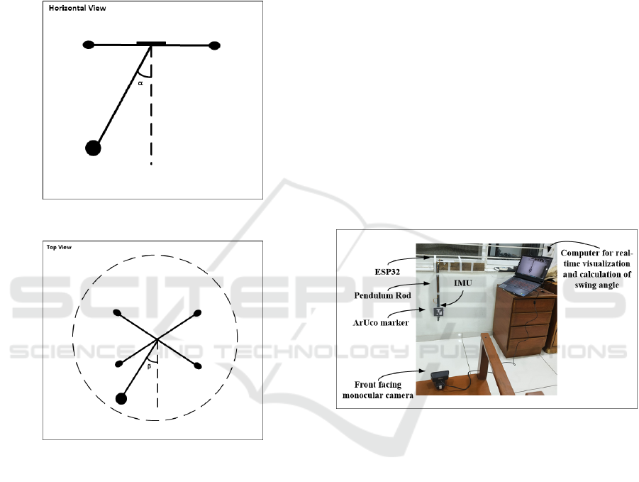
Figure 1: In-plane (vertical) swing angle, α.
Figure 2: Out-of-the-plane swing angle, β.
Figures 1 and 2 illustrate the in-plane angle, α
seen in the vertical plane in 2D motion of the drone
and β-represents the out-of-the-plane swing angle.
2.2 IMU-Based Method
In this approach, we use a Micro-Electro-Mechanical
System (MEMS) based IMU to determine the load at-
titude, specifically the planar angle α in 2D. While
many control systems estimate load attitude indirectly
using the carrier platform’s IMU and dynamic mod-
els (Nguyen and Caverly, 2021), recent studies have
explored the direct measurement of suspended load
attitude using dedicated IMUs mounted on the pay-
load. For instance, (Gao et al., 2014) developed
a wireless dual-IMU system to monitor swing an-
gles in crane operations with 0.6
◦
(max 2
◦
) accu-
racy. Thus, these approaches demonstrate that com-
pact, low-power IMUs can reliably capture the 3-DOF
orientation of suspended loads in dynamic environ-
ments. Following this, we propose the IMU-based
load attitude determination method for the suspended
load on a quadrotor system.
3 LOAD ATTITUDE ESTIMATION
AND EXPERIMENTAL
VALIDATION
The methods in this study are experimentally vali-
dated based on a simple pendulum apparatus, which
emulates the behavior of the suspended load on the
quadrotor using a fixed-length, rigid string.
The experiment has been conducted for two meth-
ods, namely, the CV-based method and IMU-based
method for the simple pendulum-like test setup as dis-
played in Figure 3.
Figure 3: Experimental setup for load attitude measurement
combining both - CV-based and IMU-based methods.
3.1 CV-Based Load Attitude Estimation
and Setup
The experimental setup of this method consists of a
Fingers 1080p webcam. It was connected to a com-
puter to capture the real-time video feed. For the im-
age processing OpenCV in Python was used. Initially,
the camera was calibrated using the checkered board
calibration technique, and the respective camera ma-
trix and distortion coefficients were derived (Bradski
and Kaehler, 2000). An ArUco marker of UID 7 of
the 5×5 ArUco Dictionary was used as a load marker.
The frame rate was set at 60 fps along with an image
resolution of 1280 × 720p. The distance between the
camera and the marker is set to 80 cm. The marker is
positioned at various points, and the angles resulting
from the algorithm developed are retrieved. The step-
Experimental Validation of Load Attitude Estimation Using Computer Vision and IMU-Based Approaches for Slung-Load Aerial Robots
373

by-step method articulating the CV-based load atti-
tude estimation is shown in the form of Algorithm 1.
The CV-based method uses a monocular camera
to capture images of the ArUco marker attached to
the load. The marker’s corners are detected, and their
2D image coordinates are mapped to 3D world coor-
dinates using the camera’s intrinsic and extrinsic pa-
rameters, obtained through calibration. The pose es-
timation is performed, which computes the marker’s
rotation and translation vectors relative to the camera.
These vectors are then used to calculate the pitch, roll
and yaw angles of the load, as well as the distance of
the ArUco marker from the camera. The algorithm
is computationally efficient and suitable for real-time
applications, provided the marker remains in the cam-
era’s field of view and under adequate lighting condi-
tions.
Data: Camera frame, ArUco dictionary,
Camera calibration parameters
Result: Pitch, Roll, Yaw, Load Distance
Initialization: Load ArUco dictionary and
camera parameters;
while camera is active do
Capture frame;
Detect ArUco markers in frame;
if marker detected then
Decode marker ID;
Estimate marker corners;
Compute pose;
Extract rotation and translation
vectors;
Calculate pitch, roll, yaw, and load
distance;
Output attitude parameters;
else
Output no detection;
end
end
Algorithm 1: CV-based Load Attitude Estimation.
3.2 IMU-Based Load Attitude
Estimation and Setup
The experimental setup of this approach consists pri-
marily of an IMU MPU6050 fitted at the load position
and an ESP32-WROOM-DA microcontroller to inter-
pret IMU data and calculate the load attitude angles.
The IMU and ESP32 are connected through the I
2
C
communication protocol. The MPU6050 transmits a
14-byte raw integer string containing accelerometer
(a
x
,a
y
, and a
z
) and gyroscope (w
x
,w
y
, and w
z
) values
to the ESP32. The code developed in C++ is then de-
ployed on ESP32 which then processes the raw data
provided by MPU6050 and converts it into physical
units. These physical units are then converted to roll
and pitch angles using trigonometric functions by the
library MPU6050-light. The final outputs are then
timestamped and sent forward to the flight controller
over I
2
C or laptop (Arduino IDE Serial Monitor) over
serial communication.
For the experimental validation of the pro-
posed system, an off-the-shelf available 6-axis IMU
MPU6050 is used to determine the load attitude, α,
and β. An ESP32 is used to read and interpret the
raw data incoming from the IMU to produce the re-
quired attitude parameters for quadrotor control. The
step-by-step method articulating the IMU-based load
attitude estimation is shown in the form of Algorithm
2.
Data: IMU sensor data (accelerometer:
a
x
,a
y
,a
z
; gyroscope: w
x
,w
y
,w
z
)
Result: Pitch, Roll, Yaw
Initialization: Initialize IMU sensor and
calibrate accelerometer and gyroscope;
while IMU is active do
Read raw accelerometer data (a
x
,a
y
,a
z
);
Read raw gyroscope data (w
x
,w
y
,w
z
);
Convert raw data to physical units (m/s
2
for accelerometer, rad/s for gyroscope);
Calculate pitch, roll and yaw angles;
Output attitude parameters (pitch, roll,
yaw);
end
Algorithm 2: IMU-based Load Attitude Estimation.
4 EXPERIMENTAL AND
SIMULATION RESULTS
This section presents the results of experimental se-
tups as proposed in previous sections and provides a
comparative analysis of the salient features of both
ArUco marker-based and IMU-based methods with
the simulation of the pendulum-based suspended-load
setup.
Table 1 presents the summary of variables taken
under consideration for the experiment.
The following Tables 2 and 3 summarize the data
collected during aggressive maneuvers using both
sensing methods. The measurements demonstrate
each method’s responsiveness and coverage across
relevant dynamic states.
The pendulum serves as a common platform for
comparison of feedback using an ArUco marker and
ICINCO 2025 - 22nd International Conference on Informatics in Control, Automation and Robotics
374
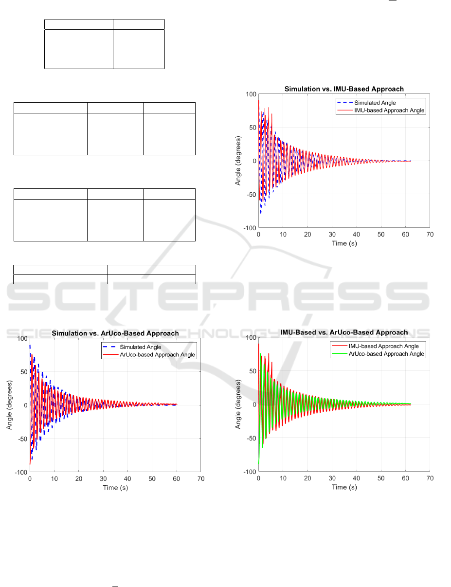
Table 1: Summary of variables obtained using both meth-
ods.
ArUco Based IMU-based
1. Pitch 1. Pitch
2. Roll 2. Roll
3. Yaw 3. Yaw
4. Load Distance
Table 2: Feedback from IMU-based method during an ag-
gressive maneuver.
Observation No. Pitch (Deg.) Roll (Deg.)
1 32.52 14.82
2 32.49 14.92
3 31.98 15.03
4 31.70 15.09
Table 3: Feedback from ArUco-based method during an ag-
gressive maneuver.
Observation No. Pitch (Deg.) Roll (Deg.)
1 -146.8 46.3
2 -138.5 53.0
3 -133.4 56.9
4 -124.5 59.6
Table 4: Summary of frequency of feedback attained.
ArUco Based Frequency IMU-based Frequency
31.21 Hz 370.48 Hz
IMU. The pendulum swing angle here is α represent-
ing the load attitude.
Figure 4: Pendulum load swing angle (α) vs Time plot for
CV-based method compared with pendulum simulation.
Figure 4 demonstrates the performance of the CV-
based feedback system. The plot shows the simulated
response of a pendulum governed by the non-linear
dynamic equation:
¨
α = −b
˙
α −
g
L
sin(α)
where damping coefficient b = 0.016
Ns
m
, length of
string L = 0.6m, α represents the angular displace-
ment of the pendulum load. These experimental data
points obtained from the physical pendulum are com-
pared with the simulated trajectory, with α corre-
sponding to the pitch angle measured using the CV-
based method.
Figure 5: Pendulum load swing angle (α) vs Time plot for
IMU-based method compared with pendulum simulation.
Figure 5 displays the performance of the IMU-
based feedback system in contrast with the simulation
of the system.
Figure 6: Pendulum load swing angle (α) vs Time plot for
both proposed methods.
The Figure 6 demonstrates the comparison of the
IMU-based and CV-based feedback system for pitch
angle, α, of the pendulum.
Experimental Validation of Load Attitude Estimation Using Computer Vision and IMU-Based Approaches for Slung-Load Aerial Robots
375
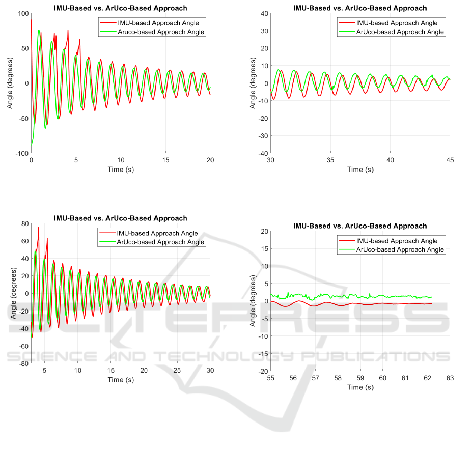
Figure 7: Anomaly in peaks of IMU-based load swing angle
during large swing angle variation (greater than ±25
◦
).
Figure 8: Another set of experimental values recorded for
IMU-based method vs. CV-based method for pendulum
swing angle.
In Figures 7 and 8, when there are greater vari-
ations in the pendulum swing angle, the IMU per-
forms poorly and is unable to accurately determine
the pendulum load swing angle. However, the CV-
based method outperforms the IMU-based method by
providing a consistent and accurate determination of
the pendulum load swing angle.
When an almost steady state condition is
achieved, the α angle obtained from the IMU-based
method exhibits better results compared to the CV-
based method, as projected in Figure 9.
As demonstrated in Figure 10, the pendulum sys-
tem tends towards the neighborhood of equilibrium
zero, i.e., near 0
◦
, the CV-based method displays very
distorted behavior, while the IMU-based method pro-
vides relatively better angle feedback α, which is very
useful in the case of quadrotor suspended load when
the swing angle of load is usually smaller in value.
Figure 9: Anomaly in peaks of swing angle (α) using CV-
based approach and IMU based approach during smaller an-
gle variations (< ±10
◦
).
Figure 10: Smaller variation of pendulum swing angle
(±5
◦
) experimental output values for both methods.
5 CONCLUSION AND FUTURE
PROSPECTS
This paper presents a comparative analysis of two
load attitude measurement methods for drones carry-
ing suspended loads- a CV based system using fidu-
cial markers and a sensor-based system employing an
IMU. Each method yields an easy to implement so-
lution offering unique advantages in different scenar-
ios. The IMU-based method performs well when the
load deviation is less (±10
◦
), and results in faster re-
sponse (approximately 370 Hz), making it easily in-
tegrable with flight controllers, making it suitable for
real-time precision maneuvering requirements when
faster control feedback is essential. Future work will
focus on integrating this system into actual flight con-
ICINCO 2025 - 22nd International Conference on Informatics in Control, Automation and Robotics
376

trol loops in quadrotor with slung load. The CV based
method, although relatively more computationally in-
tensive but provides rather accurate load attitude mea-
surements. The CV based method performs even well
for extreme maneuvers when the load deviation is
greater than ±25
◦
. However, further improvements
would be required to effectively tackle the robustness
issues that accommodate illumination variations and
camera calibration errors. In our future works, along
with the addresal of these robustness issues, we intend
to test the proposed algorithms under real-world con-
ditions, including non-rigid cables to hang the load
under the environmental disturbances for the actual
drone having suspended cargo in 3D space.
REFERENCES
Bradski, G. and Kaehler, A. (2000). Opencv. Dr. Dobb’s
Journal of Software Tools, 3(2).
de Angelis, E. L. and Giulietti, F. (2023). An improved
method for swing state estimation in multirotor slung
load applications. Drones, 7(11):654.
Deng, X., Tsukada, T., Zhu, Y., and Nam, T. (2024). Angle
estimation using infrared camera in outdoor environ-
ment. IEEE Access.
Gao, Z., Xue, Z., and Lin, C. (2014). Design and imple-
mentation of a wireless mems ahrs for crane swing
monitoring. Sensors, 14(10):18670–18687.
Garg, V., Niranjan, S., Prybutok, V., Pohlen, T., and Gligor,
D. (2023). Drones in last-mile delivery: A systematic
review on efficiency, accessibility, and sustainability.
Transportation Research Part D: Transport and Envi-
ronment, 123:103831.
Garrido-Jurado, S., Mu
˜
noz-Salinas, R., Madrid-Cuevas, F.,
and Mar
´
ın-Jim
´
enez, M. (2014). Automatic generation
and detection of highly reliable fiducial markers under
occlusion. Pattern Recognition, 47(6):2280–2292.
Guerrero-S
´
anchez, M. E., Mercado-Ravell, D. A., Lozano,
R., and Garc
´
ıa-Beltr
´
an, C. D. (2017). Swing-
attenuation for a quadrotor transporting a cable-
suspended payload. ISA Transactions, 68:433–449.
Huang, J., Xu, W., Zhao, W., and Yuan, H. (2022). An
improved method for swing measurement based on
monocular vision to the payload of overhead crane.
Transactions of the Institute of Measurement and Con-
trol, 44(1):50–59.
Lee, S. J. and Kim, H. J. (2017). Autonomous swing-
angle estimation for stable slung-load flight of multi-
rotor uavs. In 2017 IEEE International Conference on
Robotics and Automation (ICRA), pages 4576–4581.
IEEE.
Mugala, S., Okello, D., and Seruganda, J. (2020). Un-
manned aerial vehicles: Opportunities for developing
countries and challenges. In 2020 IST-Africa Confer-
ence (IST-Africa), pages 1–10. IEEE.
Nguyen, S. and Caverly, R. (2021). Cable-driven robot
payload estimation with imu-aided ekf sensor fusion.
IEEE Transactions on Instrumentation and Measure-
ment, 70:1–9.
Palunko, I., Cruz, P., and Fierro, R. (2012). Agile load trans-
portation: Safe and efficient load manipulation with
aerial robots. IEEE Robotics & Automation Magazine,
19(3):69–79.
Prajapati, P., Parekh, S., and Vashista, V. (2022). On-board
cable attitude measurement and controller for outdoor
aerial transportation. Robotica, 40(5):1650–1664.
Tang, S., W
¨
uest, V., and Kumar, V. (2018). Aggres-
sive flight with suspended payloads using vision-
based control. IEEE Robotics and Automation Letters,
3(2):1152–1159.
Thakar, P. S., Bandyopadhyay, B., and Gandhi, P. S.
(2014). Sliding mode control for an underactuated
slosh-container system using non-linear model. Inter-
national Journal of Advanced Mechatronic Systems,
5(5):335–344.
Z
´
uniga, N. S., Munoz, F., M
´
arquez, M. A., Espinoza, E. S.,
and Carrillo, L. R. G. (2018). Load transportation us-
ing single and multiple quadrotor aerial vehicles with
swing load attenuation. In 2018 International Confer-
ence on Unmanned Aircraft Systems (ICUAS), pages
269–278. IEEE.
Experimental Validation of Load Attitude Estimation Using Computer Vision and IMU-Based Approaches for Slung-Load Aerial Robots
377
