
Simulation-Driven Design and Optimization of a Parametric
Flat-Foot with Elastic Pads for a Planar Biped Robot
Koray Kadir Şafak
a
and Oğuzhan Aykut Ekşioğlu
b
Department of Mechanical Engineering, Yeditepe University, Istanbul, Turkey
Keywords: Bipedal Robot, Foot Optimization, Elastic Pads, Walking Simulation, Genetic Algorithm, Impact Mitigation.
Abstract: This paper presents the simulation-driven design and optimization of a compliant foot for a planar biped robot.
To enhance walking stability and reduce joint torques, 3D-printed elastic pads were fabricated and
experimentally characterized through compression testing. These prototypes provided baseline stiffness and
damping ranges that served as inputs to the simulation model. Using these data as a starting point, a genetic
algorithm optimized pad parameters to minimize joint torque overloads while maintaining gait stability.
Walking simulations were performed in MATLAB Simulink on flat terrain, comparing a rigid flat-foot with
the optimized compliant foot with pads. Results demonstrated up to 46% reduction in peak hip torques and
35% reduction in knee torques, along with smoother contact forces and stable zero moment point (ZMP)
trajectories. The study confirms that introducing passive compliance at the foot level improves bipedal
locomotion efficiency without additional actuation.
1 INTRODUCTION
Foot-ground interaction significantly influences the
stability, energy efficiency, and adaptability of
bipedal walking robots. Unlike rigid mechanical feet,
the human foot incorporates soft tissue structures and
arches that naturally absorb impact, assist in balance,
and conform to uneven terrain. Emulating these
biomechanical features in robotic platforms remains
a major research focus.
Various robotic foot designs have been explored
in the literature to address impact mitigation and
adaptability. Rigid flat feet are widely used due to
their simplicity, but they transmit high contact forces
to the structure. To reduce these forces, researchers
have incorporated elastic elements, such as
rubber pads (Li et al., 2008), pneumatic stiffness
adjustment mechanisms (Zang et al., 2017), and
multi-segment toe joints (ElDirdiry et al., 2017).
Sandwich structures with compliant layers (El
Asswad et al., 2017) and biomimetic feet with
embedded passive joints (ElDirdiry et al., 2017;
Venkadesan et al., 2020) have also been proposed to
approximate human foot dynamics. However, most of
a
https://orcid.org/0000-0002-4096-3712
b
https://orcid.org/0009-0007-3431-5851
these solutions require complex control or
mechanical modifications.
Recent work has also focused on optimization-
based design. For example, El Asswad et al. (2017)
used genetic algorithms to tune sandwich-type foot
parameters for impact resistance, while Venkadesan
et al. (2020) characterized stiffness properties of the
human arch to guide robotic foot design. Despite
these advances, few studies apply simulation-based
optimization specifically aimed at minimizing joint
torque within motor constraints during walking.
In this study, we propose a parametric flat-foot
design with elastic pads that balances mechanical
simplicity with improved impact buffering. Prototype
pads were fabricated via 3D printing and
experimentally characterized to determine their
stiffness and damping properties. These data provided
baseline ranges that served as inputs to the
optimization framework, rather than being treated as
fixed constants. The pads were then virtually
optimized in simulation to minimize peak joint
torques while maintaining gait stability.
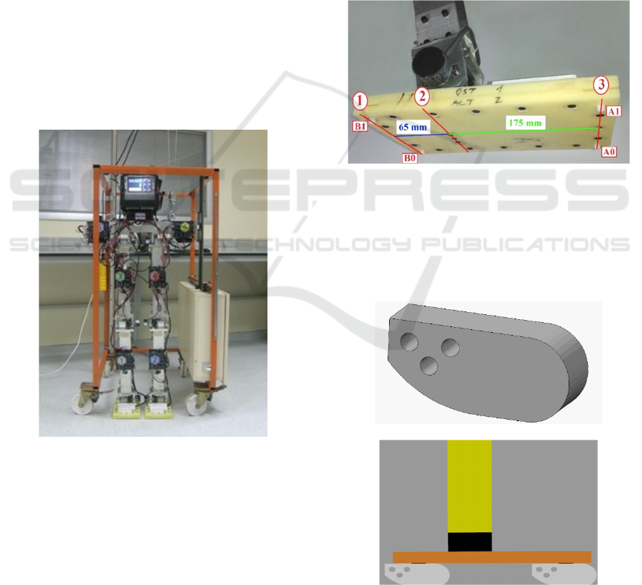
The research builds on an existing planar biped
robot platform YU-Bibot (see Figure 1), with six
actuated joints (Şafak & Baturalp, 2023). A detailed
¸Safak, K. K. and Ek¸sio
ˇ
glu, O. A.
Simulation-Driven Design and Optimization of a Parametric Flat-Foot with Elastic Pads for a Planar Biped Robot.
DOI: 10.5220/0013780000003982
Paper published under CC license (CC BY-NC-ND 4.0)
In Proceedings of the 22nd International Conference on Informatics in Control, Automation and Robotics (ICINCO 2025) - Volume 2, pages 357-362
ISBN: 978-989-758-770-2; ISSN: 2184-2809
Proceedings Copyright © 2025 by SCITEPRESS – Science and Technology Publications, Lda.
357
simulation model is constructed using MATLAB
Simulink, incorporating contact dynamics and joint
actuation profiles derived from human-inspired gaits.
Elastic pads are modelled based on
experimentally determined stiffness and damping
values. A genetic algorithm is used to optimize the
pad parameters, targeting the minimization of peak
joint torques while respecting actuator limits.
Simulation results demonstrate that the optimized
foot configuration leads to reduced impact forces and
joint loading compared to the baseline rigid flat-foot
design.
Two configurations were investigated: a baseline
rigid flat foot and a flat foot with optimized elastic
pads. Comparative analysis highlighted the
improvements in joint torque reduction, contact force
smoothing, and zero moment point (ZMP) stability.
The rest of this paper is structured as follows:
Section 2 describes the foot design and elastic pad
fabrication; Section 3 outlines the simulation
framework; Section 4 details the optimization
methodology; Section 5 presents results and
discussion; and Section 6 concludes the paper.
Figure 1: YU-Bibot planar robot platform.
2 FOOT DESIGN AND ELASTIC
PAD IMPLEMENTATION
To improve ground compliance and reduce joint
torques during walking, we extend the flat-foot
design of the planar biped robot by integrating elastic
pads under each foot. The approach is motivated by
the human foot’s ability to adapt to ground
irregularities and absorb impact through soft tissue
structures.
2.1 Flat-Foot with Pads Concept
The base configuration of YU-Bibot uses rigid flat
feet without passive or active foot degrees of freedom
(see Figure 2). To enhance compliance while
retaining structural simplicity, three modular elastic
pads are mounted beneath each foot — two forefoot
pads and one heel pad — mimicking the key contact
regions of the human foot: the big toe mound, base of
the little toe, and centre of the heel. Each pad acts as
a passive elastic element with adjustable stiffness and
damping.
Figure 2: Existing foot structure and sensors.
The geometry of the pad layout is illustrated in
Figure 3. Each pad acts as a passive elastic element and
can be independently varied in stiffness and damping.
This parametric configuration enables targeted tuning
of impact absorption and dynamic stability.
(a)
(b)
Figure 3: (a) CAD drawing of elastic pads, (b)
Implementation of pads underneath rigid foot.
ICINCO 2025 - 22nd International Conference on Informatics in Control, Automation and Robotics
358
2.2 Pad Fabrication and Material
Selection
Pads are fabricated using thermoplastic polyurethane
(TPU) via 3D printing. Two variants were tested:
orange (Shore-A 90, lower grid density) and white
(Shore-A 80, higher grid density).
Both designs use a sandwich-like internal
structure for lightweight compliance. The orange pad
weighed 36.5 g and measured 88 × 26 × 40 mm. The
grid pattern and material thickness were varied to
modify mechanical properties. These prototypes were
not the final optimized configuration but served as
experimental references for material properties.
2.3 Compression Testing and
Characterization
Quasi-static compression tests were performed using
a universal testing machine at velocities ranging from
0.5 to 3 mm/s (orange) and up to 5 mm/s (white). The
load-displacement curves were analyzed to extract
spring constants and damping coefficients.
Results confirmed light damping behavior in all
cases (i.e., ζ
eq
<1). The white pads exhibited higher
stiffness and lower damping compared to the orange
pads, making them more suitable for forefoot
implementation. Average values used in simulation
were:
• k≈65,000 N/m, c≈4 Ns/m for white pads
• k≈4,800 N/m, c≈4.2 Ns/m for orange pads
These parameters were input into the robot
simulation model to represent contact dynamics
accurately.
3 SIMULATION AND
OPTIMIZATION
FRAMEWORK
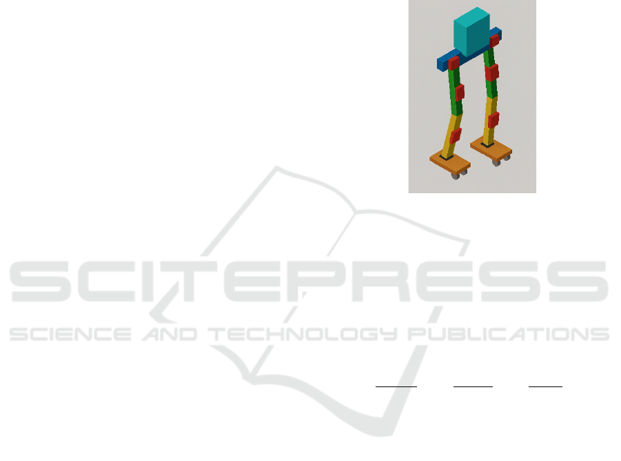
3.1 Bipedal Robot Simulation
Environment
To evaluate the effect of compliant foot design on
joint loading, a detailed simulation model of the
planar bipedal robot was constructed using MATLAB
Simulink (Simscape Multibody). The model
incorporates six actuated joints and simulates single
and double support phases using realistic contact
dynamics (see Figure 4).
Elastic pads are modelled as compliant elements
beneath each foot, with separate stiffness and
damping coefficients for forefoot and heel pads.
Contact interactions are defined using spatial contact
force blocks, and walking motions are driven by
predefined joint angle trajectories based on previous
gait studies.
Each simulation run evaluates whether the robot
maintains balance and measures maximum joint
torques at ankle, knee, and hip. A fall condition is
detected if the hip height drops below a threshold.
Figure 4: Visualization of robot simulation model.
3.2 Optimization Objective and
Constraints
The main goal is to minimize joint torque spikes
during walking by tuning pad stiffness and damping.
The objective function is defined as the squared sum
of joint torque peak values divided by each joint
actuator’s maximum continuous torque limits:
J=
ankle
max,ankle
+
knee
max,knee
+
hip
max,hip
(1)
where τ
max
values are motor torque limits (5A rated).
The squared terms place stronger emphasis on torque
values approaching or exceeding actuator limits. The
optimization criterion is based on maximum
normalized torques at ankle, knee, and hip joints over
the gait cycle, rather than mean values.
3.3 Genetic Algorithm Optimization
A genetic algorithm (GA) is used to find optimal pad
parameters:
• k
fore
,k
heel
∈
20000, 300000
N/m
• c
fore
,c
heel
∈
10000, 150000
Ns/m
These ranges were established from the
experimentally measured stiffness and damping of
3D-printed pad prototypes, which served as a basis
and starting point for the optimization rather than
fixed values. GA uses population size 50, crossover
Simulation-Driven Design and Optimization of a Parametric Flat-Foot with Elastic Pads for a Planar Biped Robot
359

probability 0.8, with convergence based on stall for
100 generations. Each evaluation runs a full walking
simulation.
3.4 Gait Generation
To simulate realistic walking dynamics, the robot’s
joint trajectories were defined based on a previously
generated walking gait for YU-Bibot. The gait was
developed through offline trajectory planning using
human-inspired profiles and validated in an earlier
work (Şafak & Baturalp, 2023).
The walking cycle consists of distinct stance and
swing phases for each leg, with ankle, knee, and hip
joints actuated via time-based reference profiles. The
gait assumes walking on flat terrain at constant
velocity and does not use feedback control during this
study. The same gait is used across all foot
configurations to ensure fair comparison between the
baseline and optimized feet.
Although the gait was initially tuned for the
baseline flat foot, the simulation revealed that the
compliant foot with pads improved torque
distribution without compromising the overall
kinematics or balance.
4 RESULTS AND DISCUSSION
4.1 Simulation Setup
The walking simulation was run using predefined
joint trajectories based on flat-ground walking gait.
Each simulation covered one full step cycle, with
joint torques monitored throughout. Two foot
configurations were compared: baseline flat-foot
(rigid sole, no compliance) and flat-foot with
optimized elastic pads (using GA-tuned stiffness and
damping).
Motor torque limits were taken as
τ
max,ankle
=24.2 Nm, τ
max,knee
=17.7 Nm, and
τ
max,hip
=11.8 Nm, based on hardware specs.
4.2 Torque Reduction Results
The simulation showed that the optimized pad
configuration substantially reduced joint torque
peaks, especially at the ankle and knee. The
comparative results are summarized in Table 1.
Table 1: Max and RMS Joint Torques – Baseline vs.
Optimized Pad Design.
Joint Metric
Baseline
(flat foot)
Optimized
(with pads)
Ankle
Max (Nm) 13.8 11.6
RMS (Nm) 4.6 4.7
Knee
Max (Nm) 31.3 20.4
RMS (Nm) 12.1 8.6
Hip
Max (Nm) 57.2 30.8
RMS (Nm) 22.1 14.2
The optimized foot with elastic pads significantly
reduced maximum joint torques across all joints, most
notably at the hip (46%) and knee (35%). These
reductions indicate improved impact buffering and
smoother load transfer during the stance phase.
RMS torques also decreased substantially at the
knee (30%) and hip (36%), which suggests a
reduction in sustained joint loading over the gait
cycle. Interestingly, the ankle RMS torque slightly
increased, likely due to the redistribution of force
during heel-strike and push-off with the compliant
pads. This trade-off appears acceptable given the
larger reductions elsewhere and the peak torque at the
ankle still remaining well below motor limits.
These results confirm that pad-based compliance
can mitigate peak loads while also reducing overall
energy demand on major joints, particularly at the
knee and hip — both of which are commonly critical
in robotic actuation systems.
4.3 Contact Force and Stability
The total vertical ground reaction force (GRF) and
zero moment point (ZMP) were analyzed for both the
baseline flat-foot and the optimized foot with elastic
pads. ZMP stability analysis follows established
approaches in (Kajita et al., 2003; Erbatur et al.,
2002). As shown in Figure 5, the rigid flat foot
produced sharp GRF peaks at heel-strike and toe-off,
with abrupt changes in load transfer. The
corresponding ZMP trajectory (Figure 6) exhibited
rapid shifts, occasionally approaching the edge of the
support polygon. These behaviors reflect the limited
compliance of the rigid sole, leading to higher impact
forces and reduced stability margins.
ICINCO 2025 - 22nd International Conference on Informatics in Control, Automation and Robotics
360
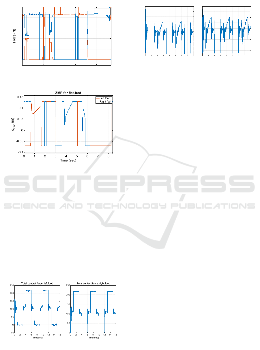
Figure 5: Total contact forces for flat foot (baseline).
Figure 6: ZMP for flat foot (baseline).
The addition of elastic pads resulted in smoother
contact force profiles with fewer sharp transients
compared to the baseline. The total ground reaction
forces (Figure 7) remained within expected limits. To
assess dynamic stability during walking, the Zero
Moment Point (ZMP) was tracked throughout the gait
cycle (Figure 8). The ZMP represents the point on the
ground where the net moment due to gravity and
inertia forces is zero, and it must remain within the
foot’s support area to ensure stable motion (Kajita et
al., 2003; Erbatur et al., 2002). For both the baseline
and optimized foot designs, the ZMP remained inside
the support polygon during the stance phase,
confirming that the robot maintained balance
throughout the simulated steps.
Figure 7: Total contact forces for flat foot with pads.
Figure 8: ZMP for flat foot with pads.
Notably, the forefoot pads converged to much
higher stiffness values than the heel pads in the
optimization, echoing the biomechanical distribution
in the human foot. This natural-like stiffness gradient
appears to enhance impact buffering at heel-strike
while maintaining push-off stability.
4.4 Discussion and Implications
The results support the effectiveness of simulation-
driven foot design using parametric compliance. Even
in a planar biped without active foot control, passive
elasticity can significantly reduce actuator demand,
improve gait stability, and protect mechanical
components.
The trade-off is a slight increase in ankle RMS
torque, possibly due to dynamic coupling effects
introduced by the pads. This could be addressed in
future work via adaptive gait tuning or a hybrid
passive-active compliance approach.
5 CONCLUSION
This study presented a simulation-driven approach to
improving the foot-ground interaction of the YU-
Bibot planar biped robot. A modified flat-foot design
with elastic pads was introduced, inspired by human
foot contact regions. Prototype pads were fabricated
and experimentally characterized to provide baseline
stiffness and damping ranges, which served as inputs
to a genetic algorithm–based optimization
framework.
Walking simulations were conducted in
MATLAB Simulink on flat terrain for two
configurations: a baseline rigid flat foot and a flat foot
with optimized elastic pads. Comparative analysis
showed that the optimized design reduced peak
torques by up to 46% at the hip and 35% at the knee,
with RMS torques also significantly reduced at these
joints. While ankle RMS torque slightly increased,
the overall load distribution across joints improved.
012345678
Time (sec)
0
50
100
150
200
Total vertical contact force
Right foot
Left foot
Force (N)
Force (N)
0246810121416
time (sec)
-0.08
-0.06
-0.04
-0.02
0
0.02
0.04
0.06
0.08
0.1
0.12
d_zmp (m)
ZMP left
0246810121416
time (sec)
-0.08
-0.06
-0.04
-0.02
0
0.02
0.04
0.06
0.08
0.1
d_zmp (m)
ZMP right
Simulation-Driven Design and Optimization of a Parametric Flat-Foot with Elastic Pads for a Planar Biped Robot
361

Ground reaction force analysis indicated that the
elastic pads smoothed impact transients compared to
the rigid baseline, while Zero Moment Point (ZMP)
trajectories remained well within the support
polygon, confirming stable walking. These results
demonstrate that introducing passive compliance at
the foot level can mitigate joint loads and enhance
stability without requiring additional actuation or
complex control.
The findings also suggest a natural-like
distribution of compliance—stiffer forefoot and
softer heel—as an effective configuration for impact
absorption and propulsion, similar to human foot
mechanics. Future work will include hardware
implementation of the optimized pad design on the
physical robot.
The proposed approach demonstrates the value of
coupling simulation, experimental characterization,
and optimization in advancing bio-inspired robotic
design.
REFERENCES
El Asswad, M., AlFayad, S., & Khalil, K. (2017).
Optimization of HYDROÏD robot foot. International
Journal of Mechanical & Mechatronics Engineering,
17(3), 63–70.
ElDirdiry, O., Zaier, R., & Al-Yahmedi, A. (2017). Design
of biomechanical legs with a passive toe joint for
enhanced human-like walking. The Journal of
Engineering Research, 14(2), 166–181.
Erbatur, K., Okazaki, A., Obiya, K., Takahashi, T., &
Kawamura, A. (2002). A study on the zero moment
point measurement for biped walking robots.
Proceedings of the 7th International Workshop on
Advanced Motion Control (AMC) (pp. 431–436).
https://doi.org/10.1109/AMC.2002.1026959.
Kajita, S., Kanehiro, F., Kaneko, K., Fujiwara, K., Harada,
K., Yokoi, K., & Hirukawa, H. (2003). Biped walking
pattern generation by using preview control of the zero-
moment point. In Proceedings of the IEEE
International Conference on Robotics and Automation
(Vol. 2, pp. 1620–1626). IEEE. https://doi.org/10.
1109/ROBOT.2003.1241826.
Li, J., Huang, Q., Zhang, Y., Yu, H., & Li, K. (2008,
September). Flexible foot design for a humanoid robot.
2008 IEEE International Conference on Automation
and Logistics (pp. 1414–1419). https://doi.org/10.
1109/ICAL.2008.4636375
Şafak, E., & Baturalp, K. (2023). Parametric design and
prototyping of a low-power planar biped robot.
Biomimetics, 8(4), 346. https://doi.org/10.3390/
biomimetics8040346
Venkadesan, M., Yawar, A., Eng, C. M., Lieberman, D. E.,
& Mandre, S. (2020). Stiffness of the human foot and
evolution of the transverse arch. Nature, 579, 97–100.
https://doi.org/10.1038/s41586-020-2053-y
Zang, X., Liu, H., Li, Z., Lin, Y., & Zhao, J. (2017). Design
and experimental development of a pneumatic stiffness
adjustable foot system for amphibious spherical robots.
Applied Sciences, 7(10), 1005. https://doi.org/10.
3390/app7101005
ICINCO 2025 - 22nd International Conference on Informatics in Control, Automation and Robotics
362
