Robust LiDAR-Based Parking Slot Detection and Pose Estimation
for Shell Eco-Marathon Vehicles
Miklós Unger
a
and Ernő Horváth
b
Research Center of Vehicle Industry, Széchenyi István University, 1 Egyetem Square, Győr, Hungary
Keywords: Autonomous Vehicles, Shell Eco-Marathon, Parking Place Detection, LIDAR.
Abstract: This paper introduces the winning algorithm of the 2024 Shell Eco-marathon Autonomous Urban Challenge
for autonomous parking. The task requires the vehicle to identify an available parking spot from multiple
alternatives and precisely navigate into it, fully remaining within the designated area without touching any
lane markings. Successful task execution requires not only reliable long-range detection of the parking space
but also an accurate final orientation relative to the parking spot. To solve this task, we propose a novel method
which relies on the combination neural networks and traditional point cloud processing methods. Since this
is a highly specific problem tailored to the Shell Eco-marathon setting, and no publicly available solutions
from other teams have been observed, our earlier algorithm serves as the primary baseline for comparison.
1 INTRODUCTION
The Shell Eco-marathon is an international university
competition that promotes the design of energy-
efficient vehicles and includes autonomous driving
challenges. In the autonomous category, participants
must complete three main tasks without any external
intervention: autonomous driving, obstacle
avoidance, and parking. SZEnergy Team is a student
team participating in this competition. The team's
vehicle is equipped with a 128-channel Ouster
LiDAR, a ZED2i stereo camera, and an inertial
measurement unit (IMU) to support autonomous
functionality. The algorithms run on an NVIDIA
Jetson Orin onboard computer, using the ROS 2
framework.
1.1 The Race
The competition consists of three main autonomous
tasks, with the third and final one being autonomous
parking. Between each task, the vehicle is required to
come to a complete stop at designated stop lines with
stop signs. The competition is typically held on a
closed racing circuit; in 2025, it took place at the
Silesia Ring in Poland.
a
https://orcid.org/0000-0003-3518-1107
b
https://orcid.org/0000-0001-5083-2073
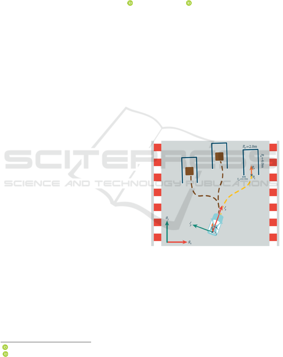
Figure 1:
Conceptual Overview of the Challenge.
Due to the layout of the track, the distance between
the last stop sign and the parking area can be as much
as 50–80 meters. This means that the available
parking spot may not be visible immediately, even to
the onboard camera. In the parking challenge, three
parking spots are placed on different parts of the track
using adhesive markings, with two of them
intentionally made unavailable. The core challenge
486
Unger, M. and Horváth, E.
Robust LiDAR-Based Parking Slot Detection and Pose Estimation for Shell Eco-Marathon Vehicles.
DOI: 10.5220/0013772900003982
Paper published under CC license (CC BY-NC-ND 4.0)
In Proceedings of the 22nd International Conference on Informatics in Control, Automation and Robotics (ICINCO 2025) - Volume 1, pages 486-493
ISBN: 978-989-758-770-2; ISSN: 2184-2809
Proceedings Copyright © 2025 by SCITEPRESS – Science and Technology Publications, Lda.
for the algorithm is to reliably detect and select the
one unoccupied parking spot, see figure 1 and 2.
Figure 1 illustrates an autonomous vehicle
maneuvering through a parking challenge consisting
of multiple slots. Each parking slot is framed by 0.15-
meter-wide blue lines with white borders (𝑝
) along
the sides and the back, defining a 2.0-meter-wide (𝑝
)
and 4.0-meter-deep ( 𝑝
) rectangular parking area.
The parking goal position is represented by the point
pt, and its desired orientation is indicated by the
vector 𝑝
(marked with an orange arrow and
displayed two times for clarity). An example
trajectory to a free parking space is shown with a
dashed yellow curve, while trajectory to an occupied
parking space is marked with brown dashed curves.
The vehicle is equipped with a body-fixed local
coordinate system, denoted as ( 𝑙
,
𝑙
), while the
global frame is labelled (𝑔
,
𝑔
). Accurate alignment
with the target pose pα is critical for successful
parking. The 𝑏
refers to the base_link frame, and the
variable distance represents the Euclidean distance
between 𝑏
and the point 𝑝
.
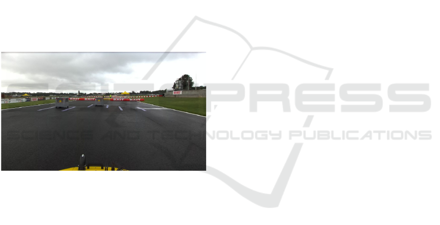
Figure 2: actual picture of the challenge.
2 THE ALGORITHM
The algorithm operates as follows. First, a trained
neural network identifies a bounding box in the image
data, which it predicts—based on a certain confidence
value—to represent a free parking space. The
algorithm is designed in such a way that, even if
multiple parking spaces are detected, it only publishes
the corner points of the bounding box with the highest
confidence on a ROS topic. This information is then
used for further processing.
Initially, these four corner points are only
available as 2D pixel coordinates. Through a
deprojection process, the algorithm converts them
into 3D coordinates and then transform them into the
appropriate reference frame using the corresponding
transforms.
Until reliable LiDAR data becomes available—as
described in the following sections—The car initiate
motion towards the estimated center of the parking
slot based solely on the bounding box identified in the
camera image.
After the corner points are transformed into the
appropriate reference frame, the LiDAR point cloud
is analysed within the defined region. Specifically,
the algorithm focuses on the ambient and intensity
values associated with the points. Based on the
observations, there is a significant difference in
ambient response between bare asphalt/concrete and
painted surfaces, with the latter typically producing
sharp peaks in the ambient signal (Jing Gong et
al.,2024).
Our objective is to identify which points in the
cloud correspond to the painted parking area. In
earlier versions of the software, this was attempted by
comparing each point’s ambient value to a global
average. In the current approach, however, the
algorithm relies solely on detecting significant peaks
in ambient values, as they have proven to be a more
reliable indicator of painted regions.
In the context of parking spot detection and the
actual parking maneuver, our algorithmic objective is
to generate a pose-type ROS topic. The position
component of this pose is defined such that its lateral
coordinate aligns with the center of the parking spot,
while its longitudinal coordinate is aligned with the
starting edge of the painted boundary lines. This
position can optionally be adjusted in the longitudinal
direction depending on how deep the vehicle is
intended to enter the parking space (Weikang et
al.,2024).
The more critical aspect, however, is the
orientation of this pose. It is essential that the vehicle
aligns itself straight within the parking area, avoiding
any skewed positioning. This requirement arises
because the camera-based parking space detector
only returns a 2D bounding box with width and
height, but without any reliable orientation
information. Therefore, the detection is augmented
with LiDAR-based analysis to derive a pose that
includes an accurate angular alignment relative to the
actual orientation of the painted parking lines (Hata
and Wolt, 2014)
The construction of the final pose proceeds as
follows: within the filtered bounding box, the LiDAR
point cloud is traversed ring by ring (i.e., by
increasing radial distance), and points exhibiting a
significant ambient value peak are collected. Ideally,
four such points can be detected per ring. Pairs of
points lying within 15 cm of each other — a threshold
chosen based on the official width specification of the
Robust LiDAR-Based Parking Slot Detection and Pose Estimation for Shell Eco-Marathon Vehicles
487
painted parking lines in the competition rulebook —
are then clustered.
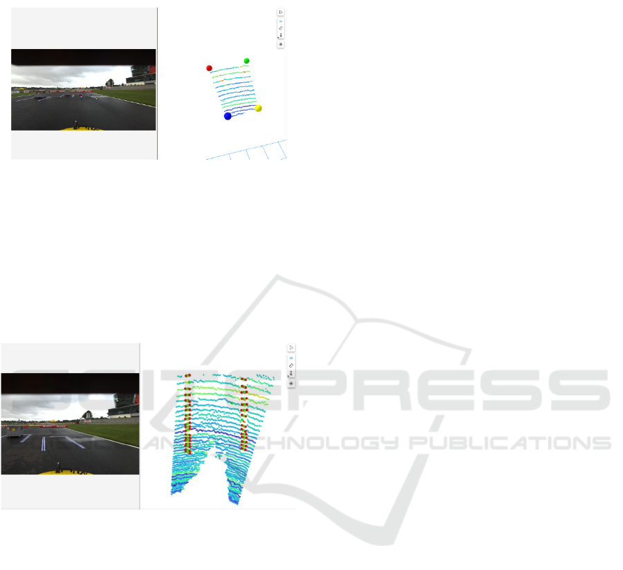
Figure 3: The original pointcloud in the deprojected area.
The points in the left represent the same points in the right
The purpose of this clustering is to compute a
representative midpoint between the two edge
markings of the parking spot These midpoints serve
as the basis for determining the centerline of the
parking space, from which the desired pose position
and orientation are derived for accurate parking
alignment (Figure 5).
Figure 4: The red dots represent the points where are the
ambient value peaks are. The green dots represent the
uncategorized points.
Once the points corresponding to the painted line
segments — hereafter referred to as uncategorized
parking points (The green dots on Figure 4) — are
obtained, the next step is to determine whether each
point belongs to the left or right side of the parking
space.
Initially, the two points closest to the bottom edge
of the bounding box are identified. The point located
nearer to the lower-left corner is designated as the
front-left point, while the other is assigned as the
front-right point.
As the vehicle approaches the parking space,
additional uncategorized parking points are detected.
These are incrementally classified as either left- or
right-side points based on their relative position and
orientation with respect to the initial front-left and
front-right references. Once at least two points have
been classified on each side, an average directional
orientation is computed per side. New points are
subsequently assigned by comparing their local
orientation to the corresponding side's average.
To minimize false detections and prevent
misclassification due to lateral noise or ambiguity, a
strict angular threshold is enforced, allowing a new
point to be associated with a side only if its orientation
deviates minimally from the corresponding average
direction.
In addition to positional and orientational criteria,
a lateral distance constraint is also incorporated when
classifying points to the left or right side of the
parking space. According to the Shell Eco-marathon
rulebook, the width of a parking space ( 𝑝
. is
specified in 2.0 meters. Therefore, during side
classification, it is verified that the distance between
a newly detected point and the corresponding point
on the opposite side falls within this acceptable range.
To account for potential sensor noise and minor
deviations in perception, a tolerance margin is
introduced. If a candidate point lies closer than 1.8 m
or farther than 2.1 m from any point already assigned
to the opposite side, it is rejected as likely noise or not
part of the actual painted boundary (Smith and
Müller, 2023).
The final pose estimation is performed once a
sufficient number of reliable points have been
classified on both sides of the parking space.
At this stage, two lines are constructed based on
the initial points from the left and right boundaries,
using the respective local orientation estimates. These
lines model the painted borders of the parking slot.
The lateral (cross-track) position is computed as
the midpoint between the two lines, effectively
aligning the pose with the centerline of the parking
space.
The longitudinal position is derived from the
positions of the front-left and front-right points,
which typically mark the entrance of the parking
space.
The orientation of the final pose is determined by
averaging the orientations of the left and right sides,
ensuring the vehicle aligns parallel to the painted
boundaries and does not park at an angle (Figure 5).
ICINCO 2025 - 22nd International Conference on Informatics in Control, Automation and Robotics
488
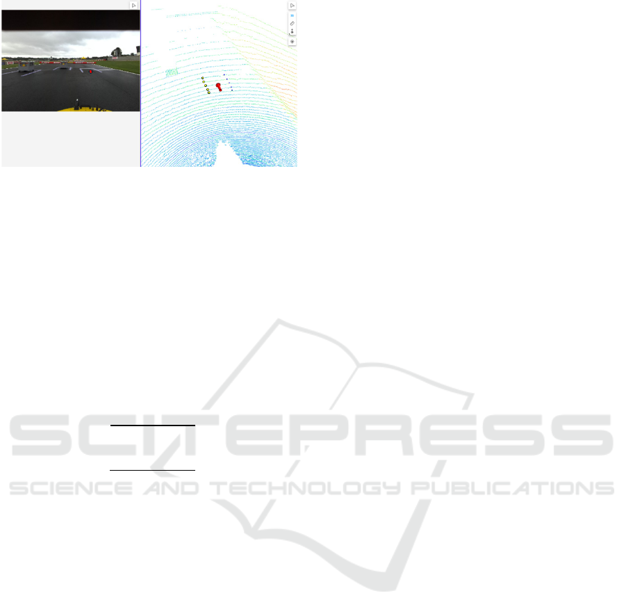
Figure 5: This figure shows the result of our algorithm. The
yellow and blue dots represent the two sides of the parking
place, the red arrow is our goal pose.
2.1 3D Point Deprojection
To transform 2D image coordinates into 3D camera-
space coordinates, a standard deprojection process
based on the pinhole camera model is applied. Given
a pixel location (𝑢,𝑣) and its corresponding depth
value 𝑍 (measured along the optical axis), the 3D
point (𝑋,𝑌,𝑍) in the camera coordinate frame can be
computed using the camera's intrinsic parameters as
follows:
𝑋
=
𝑢−𝑐
∗𝑍
𝑓
(1)
𝑌=
𝑣−𝑐
∗𝑍
𝑓
(2)
𝑍= 𝑍
(3)
Here, 𝑓
and 𝑓
represent the focal lengths in
pixels along the horizontal and vertical axes,
respectively, while 𝑐
and 𝑓
denote the optical
center (principal point) of the image. These
parameters are typically obtained from the camera's
intrinsic calibration matrix (𝐾):
𝐾=
𝑓
0 𝑐
0
𝑓
𝑐
001
(4)
This computation yields a 3D point in the camera
coordinate frame. To express this point in another
reference frame - fixed local ( 𝑙
, 𝑙
) or global
coordinate system (𝑔
, 𝑔
) - an additional rigid-body
transformation must be applied using the appropriate
extrinsic parameters (rotation and translation)
(Zhang, 2000).
2.2 Results
Before diving into the evaluation results, we first
define the three key questions this study aimed to
address:
• How does our algorithm perform under
different weather conditions?
Specifically, can we develop a method that
remains robust and functional in both ideal and
adverse environmental scenarios, such as rain?
• Can the new method effectively filter outliers,
thereby improving the robustness of the
estimated pose orientation?
Although this paper does not provide an in-
depth analysis of pose position accuracy, we
aim to indirectly enhance positional robustness
by improving orientation stability.
• To what extent does the new method impact the
difficulty of detecting parking slots?
In other words, does the added complexity of
outlier filtering and LiDAR-based refinement
compromise the system’s responsiveness or
detection range?
The comparison of the algorithms is presented
through two separate scenarios using two different
log files.
While the measurement conditions varied in terms
of location and weather, the hardware setup of the
vehicle remained identical. From a software
perspective, there is no difference in the input data
between the two versions.
There is a measurement where two parking spots
are available and the left one is free, under sunny and
ideal weather conditions and There is the second case
where there are three parking spots, with the right one
being free, under rainy weather conditions.
One of the key evaluation criteria for the proposed
method is its performance under varying
environmental conditions, particularly in comparison
to our previous parking slot detection approach. A
primary metric is the distance from which the first
valid points—belonging to either the left or right
painted boundary of the parking slot—can be reliably
detected, as well as the distance from which a full
pose can be estimated.
In rainy conditions, the new method was able to
detect valid feature points on both sides of the parking
slot from a distance of approximately 15 meters and
successfully estimate a reliable pose at 11.4 meters
from the parking slot’s entrance edge. In contrast, the
previous algorithm failed to detect painted boundary
features reliably under such weather conditions.
Robust LiDAR-Based Parking Slot Detection and Pose Estimation for Shell Eco-Marathon Vehicles
489
Under clear and sunny weather, the new algorithm
detected the parking slot boundaries at approximately
13 meters and computed the pose at approximately 11
meters, maintaining consistent performance. All
distance measurements are referenced relative to the
leading edge of the parking slot.
Another key aspect of the evaluation is the
consistency of the estimated orientation during the
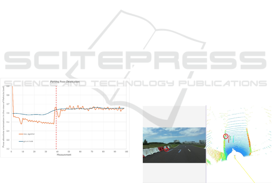
entire detection process. Figure 6 shows the absolute
orientation values of the generated poses throughout
a representative trial compared with the ground truth
value. The red dotted line marks the point where the
source of orientation data changes: the first 39 outputs
are generated by a neural network using the camera
image, and all data points after that are provided by
the LiDAR-based detection algorithm. show that the
output of our algorithm deviates from the ground
truth by a maximum of ±0.05 radians (approximately
±2.8 degrees).
During the entire measurement, the vehicle
followed a trajectory as illustrated in Figure 1,
gradually approaching the pt point
Across the full measurement sequence, the
orientation values remained centered around the
correct alignment, without significant drift or sudden
fluctuations. This level of consistency is essential for
ensuring that the vehicle aligns itself correctly within
the parking slot and avoids skewed or off-angle final
positioning (Figure 6).
Figure 6: The figure illustrates the pose orientation output
by the algorithm as a function of each measurement (X-axis
count), expressed in radians. The estimated orientations are
compared to the ground truth to evaluate the algorithm’s
accuracy. The plot includes both the predictions made by
the neural network without LiDAR input and those refined
using the LiDAR point cloud. The section to the right of the
red dashed line marks the point at which orientation
estimation begins to incorporate LiDAR data.
It is important to note that the measurements were
taken on wet asphalt, where the original version of the
algorithm—relying solely on camera input—did not
switch to the LiDAR-based method. As a result, this
particular sequence is not included in the diagram.
When comparing the results with the previous
version of the algorithm—where the main difference
lies in the method used to identify the uncategorized
parking points—a significant improvement is
observed. In the earlier implementation, the filtered
point cloud obtained through deprojection was
analysed by calculating an average ambient value.
Points presumed to belong to the painted lines of the
parking space were identified by applying a fixed
threshold based on deviation from this average.
However, when analysing the same log file, our
previous method failed to detect the parking space
under rainy conditions using the LiDAR. As a result,
the vehicle relied solely on the camera-based
bounding box detection for parking. While the final
pose estimation was still positionally acceptable, the
orientation did not fully satisfy the competition
requirements, highlighting the limitations of the prior
approach in low-visibility scenarios (Bézi, 2023).
Under sunny weather conditions, the previous
method was able to detect the first points belonging
to the painted markings of the parking space from a
greater distance—approximately 18 meters.
However, due to the absence of orientation
constraints during the classification of uncategorized
parking points into left and right categories, the older
algorithm tended to include several outliers as valid
points. These misclassifications directly impacted the
stability and accuracy of the estimated orientation,
leading to inconsistent pose definitions despite the
early detection advantage.
Figure 7: Several points from the water-filled barrier were
incorrectly categorized among the left-side points of the
parking space.
Figure 8 presents a comparison between the
orientation values estimated by the new and the
previous algorithms, evaluated against ground truth in
a measurement when both algorithms worked
correctly. The ground truth reference was established
ICINCO 2025 - 22nd International Conference on Informatics in Control, Automation and Robotics
490
through manual measurements at 25 key points using
visual aids to define the expected orientation curve.
The plot also includes orientation values derived
from the camera image; thus, during the initial ~50
frames, both algorithms output the same orientation.
As the vehicle progresses (after the red dotted line)
however, the orientation estimated by the new
algorithm remains significantly closer to the ground
truth. Most notably, the final orientation computed by
the new algorithm deviates by only 0.01 radians (≈
0.57°) from the ground truth.
Figure 8: Pose orientation comparison on a dry surface,
where both the original and the improved algorithms were
active. Similar to Figure 6, this measurement includes the
entire dataset, which explains why the outputs of the old
and new algorithms are identical before the red dashed line.
In this section, both methods relied solely on camera image
information for orientation estimation.
2.3 Key Findings
Based on the previous comparison between the two
algorithms, the following conclusions can be drawn:
• The previous algorithm is capable of detecting
points from one or both sides of the parking slot
from a slightly greater distance.
• However, it is more prone to picking up noise,
which leads to inaccurate orientation
estimation.
• It also struggles to maintain a consistent and
precise position throughout the maneuver.
• The previous algorithm did not provide usable
results under rainy conditions.
3 CONCLUSIONS
In this work, we have presented a LiDAR-based
algorithm developed for autonomous parking within
the highly constrained and competitive environment
of the Shell Eco-marathon Autonomous Urban
Challenge. The method combines neural network-
based camera detection with a robust LiDAR point
cloud analysis pipeline to derive reliable pose
estimates for precise vehicle alignment within painted
parking slots.
Our comparative evaluation against a previous
algorithm revealed several key findings. While the
earlier solution showed some advantages in early
detection range under ideal weather conditions—
being able to identify features from up to 18 meters
away—its lack of strong orientation constraints and
susceptibility to noise significantly impacted its
accuracy. This often resulted in unstable pose
estimates, particularly in the presence of nearby
environmental features such as reflective barriers or
rain-induced artifacts. Additionally, the prior method
failed to provide meaningful output under rainy
conditions, a critical limitation in real-world
scenarios.
The new algorithm, in contrast, demonstrated a
high level of robustness across varying environmental
conditions. Even in challenging rainy weather, it
successfully detected the key features of the parking
slot and generated a stable and accurate pose estimate
from more than 11 meters away. One of the most
notable advantages is the orientation stability
achieved through the improved classification and
clustering process. By using ambient signal peaks and
carefully calibrated geometric thresholds, the new
system achieved an estimated orientation that
deviated by no more than ±0.05 radians (≈ ±2.8°)
from the ground truth throughout the entire
maneuver—demonstrating consistent and accurate
alignment. Moreover, the final orientation deviated
by as little as 0.01 radians from the ground truth,
demonstrating near-perfect alignment with the
intended pose.
The practical impact of these improvements is
reflected in the SZEnergy Team’s successful
execution of the parking challenge, which played a
decisive role in securing the overall victory in the
2024 Shell Eco-marathon competition. This validates
not only the effectiveness of the proposed algorithm
but also its ability to operate reliably in real-time on
embedded automotive hardware, such as the NVIDIA
Jetson Orin platform.
Robust LiDAR-Based Parking Slot Detection and Pose Estimation for Shell Eco-Marathon Vehicles
491
Table 1: A summary of the method’s overall performance
is presented in Table 1. While the new approach slightly
reduced the effective detection range, it significantly
improved the robustness of orientation estimation and
ensured reliable performance even in adverse weather
conditions.
Evaluation Aspect Observation
Performance under
varying weather
conditions
Yes – the method
remains functional
Orientation robustness Increase
d
Detection ran
g
e Sli
g
htl
y
reduce
d
Beyond the competition, this work highlights a
promising approach for reliable low-speed
autonomous maneuvering in structured
environments. The methods introduced—such as
ambient-based LiDAR filtering, dynamic point
classification using geometric and angular thresholds,
and hybrid camera–LiDAR fusion—can be
generalized to other applications, including
autonomous valet parking or warehouse robotics.
Future work may focus on extending this
approach to support parking in unmarked or partially
occluded scenarios, incorporating learning-based
clustering for even more resilient point classification,
and adapting the system for real-time re-evaluation of
parking strategy during motion. Furthermore,
integrating confidence estimation into the pose
generation pipeline could improve fail-safety and
allow more nuanced decision-making under uncertain
conditions.
In summary, the presented solution not only meets
the specific challenges of the Shell Eco-marathon but
also offers a foundation for scalable, reliable, and
interpretable pose estimation methods applicable
across a broader range of autonomous navigation
tasks.
4 FUTURE WORKS
A key motivation behind the development of the
presented multi-modal fusion approach is the inherent
limitation of our current vision-based neural network.
At present, the network provides only an axis-aligned
2D bounding box around the detected parking space
in the image plane, which contains no information
about the orientation of the parking slot relative to the
vehicle (Xu and Hu, 2020). This lack of angular
precision can lead to suboptimal initial pose
estimates, which in turn increases the reliance on
downstream corrections derived from LiDAR-based
geometric analysis.
To address this limitation, one of our primary
directions for future development is to enhance the
neural network's output by moving beyond bounding
box predictions (G. S. Wong et al.,2023).
Specifically, we plan to investigate neural
architectures that are capable of detecting the precise
corner points of the parking space markings. By
obtaining four distinct corner points, it would become
possible to estimate not only the location but also the
rotation of the parking slot directly from the image
data, yielding a more informative and structured
representation of the target area (Figure 9) (Zhang et
al., 2023).
Figure 9: The goal is to develop a neural network capable
of detecting the corner points of the parking spot.
This refined output could then be fused with
LiDAR-based data in a more synergistic manner. The
vision-based orientation estimate could provide a
strong prior for initializing the pose, while the LiDAR
data could serve as a robust source of confirmation
and fine-tuning, especially in less favorable
environmental conditions (e.g., poor lighting,
occlusions, or rain). This would result in a more
balanced fusion where both modalities contribute
complementary strengths—visual perception offering
contextual understanding and semantic cues, and
LiDAR providing precise geometric verification.
Ultimately, by combining structured visual output
with LiDAR refinement, we expect to achieve greater
robustness, improved early pose estimation, and
reduced computational effort required for correction.
This could also open the door to real-time, low-
latency pose estimation suitable for dynamic
decision-making in competitive autonomous racing
scenarios.
ICINCO 2025 - 22nd International Conference on Informatics in Control, Automation and Robotics
492

AKNOWLEDGEMENT
The research was supported by the European Union
within the framework of the National Laboratory for
Autonomous Systems. (RRF-2.3.1-21-2022-00002).
REFERENCES
A. Hata and D. Wolf, "Road marking detection using
LIDAR reflective intensity data and its application to
vehicle localization," 17th International IEEE
Conference on Intelligent Transportation Systems
(ITSC), Qingdao, China, 2014, pp. 584-589, doi:
10.1109/ITSC.2014.6957753.
Bézi, P. (2023). Stop sign and parking place detection with
camera and LIDAR datas for Shell Eco-marathon
autonom race. In F. Szauter, D. Pup, D. Csikor, R.
Földesi, & B. M. Nagy (Eds.), Applications of artificial
intelligence systems in mobility – Conference
proceedings, Spring 2023 (pp. 9–22). Széchenyi István
University. ISBN: 978-615-6443-29-8
G. S. Wong, K. O. M. Goh, C. Y. Tee, and A. Q. Md. Sabri,
“Review of Vision-Based Deep Learning Parking Slot
Detection on Surround View Images,” Sensors, vol. 23,
no. 15, p. 6869, 2023, doi: 10.3390/s23156869.
Jing Gong, Amod Raut, Marcel Pelzer, Felix Huening,
“Marking-Based Perpendicular Parking Slot Detection
Algorithm Using LiDAR Sensors”, Vehicles, vol. 6,
no. 4, pp. 1717–1729, 2024.
Smith, J., & Müller, A. (2023). Perception, positioning and
decision-making algorithms adaptation for an
autonomous valet parking system based on
infrastructure reference points using one single LiDAR.
IEEE Transactions on Intelligent Transportation
Systems, 24(3), 456–467. https://doi.org/10.1109/
TITS.2023.1234567
Weikang Yang, Dagang Li, Wei Xu, Zhide Zhang, “A
LiDAR-Based Parking Slots Detection System”,
International Journal of Automotive Technology,
vol. 25, no. 2, pp. 331–338, 2024.
Xu, C., & Hu, X. (2020, April). Real Time Detection
Algorithm of Parking Slot Based on Deep Learning and
Fisheye Image. In Journal of Physics: Conference
Series (Vol. 1518, No. 1, Article 012037). IOP
Publishing. https://doi.org/10.1088/1742-
6596/1518/1/012037
Z. Zhang, “A Flexible New Technique for Camera
Calibration,” IEEE Trans. Pattern Anal. Mach. Intell.,
vol. 22, no. 11, pp. 1330–1334, Nov. 2000.
Z. Zhang, L. Tian, C. Liu, D. Wang, and Y. Liu,
“Transformer-Based Parking Slot Detection Using
Fixed Anchor Points,” IEEE Access, vol. PP, pp. 1–1,
Jan. 2023, doi: 10.1109/ACCESS.2023.3315738.
Robust LiDAR-Based Parking Slot Detection and Pose Estimation for Shell Eco-Marathon Vehicles
493
