Pressing Force Regulation in Robotic 3D Printing
via CFD-Aided Nozzle Posture Control
Shinichi Ishikawa
1
, Ryo Yamada
1
, Wakana Tsuru
2a
and Ryosuke Tasaki
1b
1
Department of Mechanical Engineering, Aoyama Gakuin University, Kanagawa, Japan
2
Institute of Ocean Energy, Saga University, Saga, Japan
Keywords: Robotic 3D Printing, CFD Analysis, Force-Feedback Control, Extrusion Control, Force Sensing.
Abstract: In the 3D printing process of applying materials, inadequate extrusion pressure critically deteriorates the
deposition quality in robotic 3D printing. Feedback-based motion control with sensing and AI technology has
been studied to respond to uneven and flexible surfaces, but challenges remain in optimizing the application
force according to the situation. In this study, we investigate numerically and experimentally how the nozzle
can change its orientation during the printing motion in a way that reduces the extrusion force. Numerical
calculations are performed to derive the relationship between the clearance between the nozzle and the base
and the extrusion force for multiple nozzle orientation patterns. Based on the numerical results, the
relationship between the operating quantity (clearance) and the control quantity (maximum pressure and line
width) is expressed mathematically to predict the quality model based on numerical fluid dynamics. In a
variable-thickness printing experiment using a robot arm, a convex shape was reproduced by robot motion
control that continuously changed the nozzle orientation. The experimental results demonstrated that adjusting
the nozzle orientation effectively maintained extrusion force, preventing a reduction of approximately 0.01 N,
as verified through force sensor-based inspection.
1 INTRODUCTION
3D printing technology is a processing method that
creates 3D shapes by applying layers of material
ejected from a nozzle (Volodymyr K. et al., 2024).
Compared to conventional processing methods, this
method allows for more flexible processing, making
it suitable not only for desktop-scale printing but also
for large-scale printing such as architectural 3D
printing using concrete materials. Furthermore, as an
advanced application of 3D printing technology, the
technology is being developed for printing on the
ground (Salvatore B. et al., 2024), curved surfaces
(Jin Y. et al., 2016), and flexible surfaces (M.
Miyatake et al., 2020). However, the effects of
printing motion parameters and nozzle orientation on
the shape of the printing line and the underlying
foundation have not been fully elucidated.
Conventional additive technologies are mainly
used for printing on a flat surface and in environments
with little disturbance, and there are few examples of
a
https://orcid.org/0000-0002-8590-3019
b
https://orcid.org/0000-0002-3619-4498
printing on products or in environments with complex
conditions. Feedback-based 3D printing methods
using sensing methods (thickness control of printing
lines (Rob J. et al., 2017), width control of printing
lines (E. Shojaei et al., 2020), path change (S.
Ishikawa et al., 2023), and feed rate change (Philip F.
et al., 2022)) are being actively promoted to deal with
printing methods in complex environments with a lot
of uncertainty.
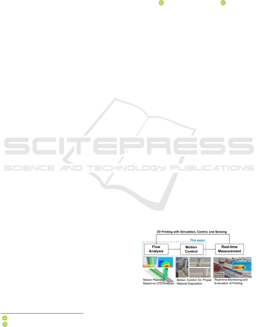
Figure 1: 3D printing process with CFD analysis and
motion control.
Ishikawa, S., Yamada, R., Tsuru, W. and Tasaki, R.
Pressing Force Regulation in Robotic 3D Printing via CFD-Aided Nozzle Posture Control.
DOI: 10.5220/0013748100003982
Paper published under CC license (CC BY-NC-ND 4.0)
In Proceedings of the 22nd International Conference on Informatics in Control, Automation and Robotics (ICINCO 2025) - Volume 2, pages 91-95
ISBN: 978-989-758-770-2; ISSN: 2184-2809
Proceedings Copyright © 2025 by SCITEPRESS – Science and Technology Publications, Lda.
91
This study aims to clarify the effects of clearance and
nozzle orientation on the extrusion force using
numerical simulation and experiments. By
conducting numerical simulation under multiple
patterns of orientation angle conditions, the
relationship between the amount of manipulation,
including orientation and control in 3D printing is
evaluated to achieve quality model prediction based
on numerical fluid dynamics. The proposed 3D
printing approach with CFD analysis and motion
control is illustrated in Figure 1. In addition, a convex
shape is produced by a printing experiment utilizing
the orientation change of the nozzle by robot motion
control, and the effect of the orientation change of the
nozzle on the extrusion force is observed.
2 PRESSING FORCE CONTROL
AND ROBOTIC-ARM-BASED
3D PRINTING SYSTEM
2.1 Robotic-Arm-Based 3D Printing
and Force Measurement System
The Robotic-arm-based 3D printing system and the
measurement device for extrusion force measurement
are shown in Figure 2. The extruder using a stepping
motor is installed at the end of a 6-DOF robot arm to
perform multi-axis dispensing motions. A force
sensor with a fixed acrylic plate is used to measure
the force with which the dispensed material is
applied.
Figure 2: Appearance of the dispensing mechanism with
force measurement device.
A 6-axis force sensor with a rated capacity of ±50 N
in the Z-direction and a resolution of 1/4000 was
employed. Sensor values are measured in a PC with a
low-pass filter to remove noise.
Mortar putty (HI Level Super, KLASS) is used as
a printing material, which possesses specific viscosity
and yield value, making it suitable for construction
applications. The powdered putty is combined with
water, loaded into a syringe, and then dispensed.
Upon contact with water, the material undergoes a
reaction and solidifies after a certain period.
Figure 3: Simplified flow rate model for determining
dispensing operations.
2.2 Simplified Flow Rate Model for
Determining Dispensing Operations
A simplified flow rate model was developed to
determine the dispensing operation based on nozzle
movement, including nozzle orientation. The
relationship between the shape of the dispensed line
formed by dispensing, and printing parameters such
as clearance and nozzle orientation angle, is
represented as shown in Figure 3. Since the discharge
flow rate from the nozzle is equal to the dispensed
flow rate, this relationship can be expressed by the
continuity equation as shown in Equation (1).
In the simplified flow rate model represented by
Equation (1), the discharge flow velocity of the
material is denoted as 𝑈 [mm/s], the nozzle diameter
as 𝐷 [mm], and the nozzle feed velocity as v
x
[mm/s].
The dispensed line width, thickness, and cross-
sectional area correction coefficient are denoted as 𝑤
[mm], ℎ [mm], and 𝐶 [-], respectively. Based on our
previous research(S. Ishikawa et al., 2025), the value
of 𝐶 is assumed to be 0.8.
In the proposed convex shape printing method,
convex shapes are formed by altering the thickness
through changes in nozzle orientation. To establish a
one-to-one relationship between the rotation direction
and clearance variation, the rotation center during
nozzle orientation changes is set at the edge of the
nozzle outlet, as illustrated in Figure 3.
𝜋𝐷
𝑈/4 ℎ𝑤𝐶𝑣
(1
)
ℎℎ
𝐷sin𝜃
(2
)
The line thickness ℎ of the printed structure is
determined by the sum of the clearance ℎ
𝐺
at the
lowest point of the nozzle outlet and the clearance
ICINCO 2025 - 22nd International Conference on Informatics in Control, Automation and Robotics
92
variation due to the orientation angle 𝜃. The
dispensing operation is determined using this
relationship. The correlation between clearance and
line thickness is expressed in Equation (2).
3 NUMERICAL SIMULATION OF
DISPERSED MATERIAL
Using numerical simulation software, the effect of the
proposed convex-shape printing operation on mortar
putty was analysed. Pressure distribution changes
during clearance increases and nozzle orientation
changes are visualized.
3.1 Numerical Calculation Method
Numerical calculations were conducted to visualize
pressure distribution. As shown in Figure 3, the
mortar putty is discharged from the nozzle outlet and
flows outside the calculation domain. The calculation
focused on a steady-state flow within the domain. The
calculation domain is indicated in Figure 4. The
steady, incompressible Navier-Stokes equations
for mortar putty-air two-phase flow were solved
using Ansys Fluent 2024 R2. The calculation
conditions are summarized in Table 1.
Figure 4: Calculation domain for simulate of 3D printing
process.
Table 1: Main parameters of 3D printing simulation.
Nozzle diameter D [mm] 10
Feed velocit
y
v
x
[mm/s] 10
Dis
p
ensin
g
velocit
y
U [mm/s] 5.3
Clearance h
G
[mm] 4
Nozzle orientation angle θ [°]
0
Density ρ [kg/m
3
] 800
Viscosity µ [kg/(m・s)]
1000
Gravitational acceleration
g
[m/s
2
] 9.81
The viscosity of the mortar putty was estimated
based on literature values (N. Izumo et al., 2008), and
its density was measured from the bulk density. Since
the flow of mortar putty is dominated by viscous
forces over inertial forces, it was treated as laminar.
For this flow analysis, the Volume of Fluid (VoF)
model, a type of two-phase flow calculation model,
was utilized. Assuming symmetry in the 𝑧-𝑥 plane,
only half of the domain was solved. A structured grid
with 250,000 nodes was employed.
The 𝑧-𝑥 plane was set as a symmetry boundary,
and the average velocity of mortar putty at the nozzle
outlet tip, as shown in Table 1, was applied at the inlet
boundary in Figure 4. The lower wall velocity was set
to -𝑣
𝑥
, solving the flow in the relative coordinate
system of the nozzle. For the air flow outside the
nozzle, the right boundary of Figure 3 was set as an
inlet boundary for air with a velocity of -𝑣
𝑥
.
The nozzle and lower wall were treated as no-slip
walls, while other surfaces, including the mortar-air
boundary, were treated as open to the atmosphere.
The computational domain reflecting these
conditions is illustrated in Figure 4.
3.2 Pressure Distribution Changes
by Nozzle Orientation
The effects of conventional 3-degree-of-freedom
printing and the proposed multi-degree-of-freedom
printing methods on discharged materials were
investigated through numerical simulation. Based on
the simplified flow rate model in Equation (1), a
scenario was considered where the printed line
(a) without clearance change and orientation change
(b) with clearance change to 8 mm
(c) with orientation change to 23.6-degree to 8 mm
Figure 5: Pressure distribution in longitudinal section and
on substrate.
Pressing Force Regulation in Robotic 3D Printing via CFD-Aided Nozzle Posture Control
93
thickness varies from 4 mm to form a convex shape.
Two cases were compared: increasing the clearance
from 4 mm to 8 mm to achieve a 4 mm thickness
increase and altering the nozzle orientation to achieve
the same thickness increase.
For the conditions in Table 1, Figure 5(a) shows
the pressure results obtained by the simulation for the
vertical and bottom surfaces of half the domain.
Figures 5(b) and (c) depict the results for an 8 mm
clearance increase and a 23.6° nozzle orientation
change, respectively. Comparing Figures 5(b) and (c),
the positive pressure distribution range of the mortar
putty in contact with the bottom surface was broader
in the clearance increase case. However, the
maximum pressure was 8,245 Pa in the nozzle
orientation case and 5,794 Pa in the clearance
increase case, showing a 1.42-fold higher pressure in
the former.
4 MEASUREMENT OF
PRESSING FORCE IN CONVEX
SHAPE PRINTING
In convex printing using nozzle orientation changes,
multiple convex shapes were reproduced to
investigate the effect of nozzle orientation changes on
extrusion force. The extrusion force was extracted
from the load values.
4.1 Experimental Conditions
Using the experimental setup shown in Figure 2, the
extrusion force during the printing of identical convex
shapes was measured and compared for cases of
clearance change alone and nozzle orientation change
alone. Both the clearance and orientation change
cycles were 4 seconds, with convex shapes formed at
four locations. Other printing parameters were
determined by referencing section 3 to match
numerical calculation conditions.
4.2 Results of The Convex Shape
Printing Experiment
The printed line appearances for each operation are
shown in Figure 6, and the Z-direction load
measurements from the force sensor are presented in
Figure 7. Figure 7(a) confirms that extrusion force
decreases during convex shape printing. Figure 7(b)
extracts extrusion force changes by subtracting sensor
values during printing without clearance or
orientation changes. It shows that the reduction in
(a) without clearance change and orientation change
(b) with clearance change
(c) with orientation change
Figure 6: Printed line by printing motion with clearance and
orientation change.
(a) measured pressing force of z direction
(b) difference in each force of z direction
Figure 7: Comparison of measured pressing forces by each
printing motion.
extrusion force during convex shape printing is
approximately 0.01 N smaller in the nozzle
orientation case than in the clearance change case.
This suggests that limiting clearance increases
through orientation changes can mitigate extrusion
force reduction.
Furthermore, this experimental tendency is
consistent with the CFD analysis presented in Section
ICINCO 2025 - 22nd International Conference on Informatics in Control, Automation and Robotics
94

3. The numerical results indicated that, for the same
convex height increase, the nozzle orientation change
produced a more concentrated pressure distribution
and a higher maximum pressure (1.42 times greater)
compared to the clearance increase case. The
experimental observation of smaller force reduction
therefore supports the simulation outcome,
confirming that nozzle orientation control effectively
maintains extrusion pressure. This agreement
between simulation and experiment demonstrates that
the CFD-derived pressure distribution can serve as a
predictive model for extrusion force behavior in
robotic 3D printing.
5 CONCLUSIONS
In this study, a 3D printing method utilizing nozzle
orientation changes via a robotic arm was verified
through numerical simulation and physical
experiments to suppress the decrease in extrusion
force and achieve high-quality 3D-printed structures.
In the numerical simulation, the effect of the
clearance between the nozzle and the base on the
extrusion force was evaluated, considering multiple
nozzle orientation angles. Furthermore, it was
confirmed that the maximum pressure becomes 1.42
times greater during orientation changes compared to
clearance changes, indicating its contribution to the
local enhancement of the extrusion force.
Furthermore, in experiments using robotic motion
control, the printing of convex shapes was
successfully reproduced through continuous nozzle
orientation changes. Quality inspection utilizing a
force sensor confirmed that the proposed printing
method suppressed the reduction in extrusion force by
approximately 0.01 N.
In this paper, a new 3D printing framework based
on CFD analysis is introduced, and this study
provides novel insights into the effect of nozzle
orientation on extrusion force during robotic 3D
printing. These findings highlight a novel design
perspective in robotic 3D printing that leverages
multi-axis motion planning informed by fluid
dynamics.
REFERENCES
Jin Yuan, Jianke Du, Yong He, and Guoqiang Fu (2016).
Modeling and process planning for curved layer fused
deposition, The International Journal of Advanced
Manufacturing Technology, Volume 91, pp. 273–285.
Mako Miyatake and Aoi Watanabe (2020). Interactive cake
decoration with whipped cream, ICMR '20:
International Conf. on Multimedia Retrieval, pp. 7–11.
Naoto Izumo and Hisanori Oda (2008). Observing the cure
processes of cement materials based on static viscosity
measurements, Ceramics Japan, Volume 3.
Philip F. Yuan, Qiang Zhan, Hao Wu, Hooi Shan Beh, and
Liming Zhang (2022). Real-time toolpath planning and
extrusion control (RTPEC) method for variable-width
3D concrete printing, Journal of Building Engineering,
Volume 46, 103716.
Rob J. M. Wolfs, Freek P. Bos, Emiel C. F. van Strien, and
Theo A. M. Salet (2017). A real-time height
measurement and feedback system for 3D concrete
printing, High Tech Concrete: Where Technology and
Engineering Meet, pp. 2474–2483.
Salvatore Bruno, Giuseppe Cantisani, Antonio D’Andrea,
Kristian Knudsen, Giuseppe Loprencipe, Laura
Moretti, et al. (2024). A small robot to repair asphalt
road potholes, Infrastructure, Volume 9, pp. 210–227.
Shinichi Ishikawa, Takahito Yamashita, and Ryosuke
Tasaki (2023). Vision-based monitoring and control for
3D printing process with dynamic ROI and path
modification algorithm, Journal of Advances in
Information Technology, Volume 14, No. 6, pp. 1443–
1449.
Shinichi Ishikawa, Ryo Yamada, and Ryosuke Tasaki
(2025). High-sensitivity Interlayer Force Measurement
and Multi-layer Smoothing Control for 3D Printing on
Uneven Surfaces, SICE Journal of Control,
Measurement, and System Integration, Volume 18,
Issue 1.
Shojaei Barjuei, E., Courteille, E., D. Rangeard, F. Marie,
and A. Perrot (2020). Real-time vision-based control of
industrial manipulators for layer-width setting in
concrete 3D printing applications, Advances in
Industrial and Manufacturing Engineering, Volume 5,
100094.
Volodymyr Khyzhynskyi, Mykola Lampeka and Valerii
Strilets (2024). The history of the development of 3D
printing technologies and their use in world artistic
ceramics, History of science and technology, Volume
14, issue 1, pp. 152-183.
Pressing Force Regulation in Robotic 3D Printing via CFD-Aided Nozzle Posture Control
95
