
Automated Process Control for the Beam Gas Curtain Vacuum
System at CERN
L. Cantu, R. Ferreira, J. Francisco Rebelo, A. Rocha, C. Vazquez Pelaez and L. Zygaropoulos
CERN, European Organisation for Nuclear Research, 1211 Meyrin, Switzerland
Keywords: Vacuum Control Systems, Process Automation, Machine Safety, SCADA Interface, Staged Commissioning,
Validation.
Abstract: The Beam Gas Curtain (BGC) system is a key diagnostic instrument for non-invasive proton beam profiling
in the Large Hadron Collider (LHC), relying on precise and safe gas injection into the beam pipe. Initially
operated via manual procedures through a supervisory control and data acquisition (SCADA) interface, BGC
injections required expert users, were time consuming and vulnerable to human error. This paper presents the
design and implementation of an automated gas injection control system, fully integrated within the LHC
Vacuum Control System SCADA and using Vacuum Framework. The solution includes a finite state machine
(FSM) deployed on a programmable logic controller (PLC), a new state-aware SCADA interface, and a
comprehensive interlock strategy combining device-level and process-level safety. The system was
extensively tested using simulations and staged commissioning, culminating in a successful deployment
during the LHC Year-End Technical Stop (YETS) 2024/25. Automation has drastically simplified operations,
increased reliability, and enhanced machine safety, requiring only two user actions to initiate an injection.
1 INTRODUCTION
The Beam Gas Curtain (BGC) is a promising
diagnostic tool for the High-Luminosity upgrade of
the LHC, providing non-invasive, high-resolution
profiling of the proton beam. Installed at Point 4 of
the LHC, it relies on the interaction between a
supersonic gas jet and the particle beam to create
fluorescence, enabling accurate 2D beam profile
imaging (Salehilashkajani et al., 2022).
The BGC operates by expanding high-pressure
gas through a specially designed nozzle (Tzoganis &
Welsch, 2013) into what is known as the injection
chamber, where the gas jet is shaped by a series of
three skimmers. The gas curtain, which is tilted 45
degrees relative to the horizontal plane, then
intersects the particle beam.
Finally, the curtain continues toward a dump
chamber where the gas is evacuated and a last
skimmer is used to not permit gas to reenter the
interaction chamber (Sequeiro et al., 2024).
The BGC was initially installed in the LHC during
YETS 2022/23 with dedicated vacuum equipment
and a manually operated control system. This paper
will describe the vacuum control system currently
used for BGC operation, which has enabled automatic
gas injection with only two user actions.
2 BGC LAYOUT AND CONTROLS
2.1 Vacuum Equipment
In Figure 1 we can see the layout of the BGC vacuum
system. A core element is the set of five fixed
pumping groups, each composed of a primary (PP1 to
PP5) and a turbomolecular pump (TMP1 to TMP5).
Three gate valves (VVGINJ, VVGDUMP and
VVR4) have the important functionality of isolating
the interaction chamber from the other chambers of
the BGC instrument and from the dedicated pumping
group. The injection line that supplies the BGC with
gas houses three injection valves (VVA1, VVA2 and
VVA3) used to start the gas injection. A primary
pump (PPINJ) is used to pump the gas remaining in
the nozzle after injections using the injection line.
Pressure throughout the volumes and the pumping
groups is monitored using piezoelectric (VGM0,
VGM1, VGM2), Pirani (VGR1A, VGR1B, VGR2,
VGR3, VGR4B, VGR5A and VGR5B) and Penning
282
Cantu, L., Ferreira, R., Rebelo, J. F., Rocha, A., Pelaez, C. V. and Zygaropoulos, L.
Automated Process Control for the Beam Gas Curtain Vacuum System at CERN.
DOI: 10.5220/0013744900003982
Paper published under CC license (CC BY-NC-ND 4.0)
In Proceedings of the 22nd International Conference on Informatics in Control, Automation and Robotics (ICINCO 2025) - Volume 1, pages 282-289
ISBN: 978-989-758-770-2; ISSN: 2184-2809
Proceedings Copyright © 2025 by SCITEPRESS – Science and Technology Publications, Lda.
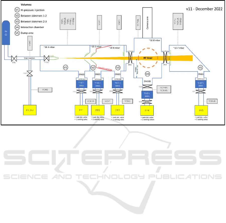
Figure 1: Layout of the BGC Vacuum System (Ady & Sequeiro, 2022).
(VGP1, VGP2, VGP3, VGP4A, VGP4B, VGP5)
gauges. In addition, the injection line is equipped with
two pressure transmitters (VGA1 and VGA2) to
monitor the pressure of the gas to be injected.
2.2 Vacuum Framework
The control of the BGC equipment is implemented
using the CERN Vacuum Framework, which consists
of a library of baseline PLC functions implemented
using structured text, common SCADA panels,
control scripts and files, ORACLE databases to store
device data, and vacCC, an application which allows
users to modify vacuum devices via a web browser
and which automatically generates SCADA and PLC
configuration files (Rocha et al., 2019). The
framework is essential to enable the configuration,
maintenance and operation of the very large
distributed vacuum control systems at CERN
(Antoniotti et al., 2014). Each vacuum device in the
framework is instantiated from what is known as a
control type, within which everything needed to
manage the equipment is defined.
Vacuum framework devices can be operated
either in automatic or manual mode. When the
equipment is in manual mode it can only receive
manual commands from users operating the SCADA,
whilst when in automatic mode the device is under
the control of an automatic process in the PLC. Only
operators with high enough permissions can swap
devices between automatic and manual modes.
Normal users can generally not manually operate a
device which is being controlled by a process.
2.3 Control System
The control system developed for the BGC consists
of six PLCs. Each of the five pumping groups is
controlled by a dedicated PLC (Simatic S7-1200), as
they are implemented using the standard solution for
fixed vacuum pumping groups on the LHC developed
at CERN (Ferreira et al., 2016). Finally, a sixth
controller is used to handle the rest of the equipment
as the main PLC of the BGC control system.
All Pirani and Penning gauges are managed by
dedicated controllers (Pfeiffer TPG300), which
interface with the PLCs through Profibus. The
piezoelectric gauges are connected to a standard
controller for LHC piezoelectric gauges developed at
CERN (Chatzigeorgiou & Kuhn, 2024), from which
the main PLC acquires pressure values through 0-10V
signals.
Finally, the pressure transmitters, gate valves and
injection valves are all controlled through the main
PLC I/O (Zygaropoulos, 2022).
2.4 Machine Safety
Given that the BGC injects gas directly into the LHC
beam pipe close to crucial and sensitive equipment
Automated Process Control for the Beam Gas Curtain Vacuum System at CERN
283

such as the radio frequency cavities that accelerate the
particle beam, machine safety must be a critical part
of the control system design, both at the hardware and
software levels.
2.4.1 Control Hardware Safety
Considerations
At the hardware level, all PLCs and equipment
controllers are connected to a UPS, meaning that if a
power loss is experienced during gas injection, the
injection and gate valves can still be operated and the
pressure in the chambers can still be monitored.
Pumping group devices, though, are powered
locally in the LHC tunnel to adhere to the standard
LHC fixed pumping group control architecture
(Ferreira et al., 2016) (as normally pumping groups
are placed very distant from the control rack location
and would experience too large a voltage drop),
meaning that in the case of power loss, they are not
connected to backup power (as UPS connections are
not available in the LHC tunnel).
The standard hardware that controls vacuum
pumping groups at CERN is designed to vent both the
turbo-molecular and primary pump of a pumping
group after a power loss using a charged capacitor
(Zygaropoulos & Wickham, 2024).
The BGC is the only case in the LHC where the
following two types of pumping group configurations
are found: pumping groups without isolating valves,
and a pumping group with a turbo-molecular pump
equipped with a venting valve. These configurations
have fewer intermediate valves directly controlled by
the pumping group between the beam pipe and
venting points.
It was decided, therefore, to remove the automatic
venting functionality, as it is of the utmost importance
to minimize any possible risk of venting the beam
pipe.
The compressed air lines that supply the pumping
group, injection and gate valves are provided with
reservoirs. If there is a loss of both the compressed air
and the reservoir, the gate valves will not close
automatically as they are bistable, but the injection
valves will close automatically, avoiding the risk of
continued injection.
2.4.2 Device Interlocks
Software interlocks, called device interlocks in this
context, are also used in this system to ensure the
machine safety of the LHC. Device interlocks are
separated in two categories:
Start interlocks, which permit or not, a valve to
open or a pumping group to start but will not
close or stop them if open or running.
Full interlocks, which do not allow a valve to
open or a pumping group to start and will close
or stop them if open or running.
Given the critical nature of the BGC, when
operating the instrument manually, devices which
have been interlocked must be manually reset through
the SCADA after the underlying interlock condition
has been cleared. This is required in order to re-
acquire control of the equipment and resume normal
operation.
Table 1: Start interlock conditions for each device.
Device Start Interlock conditions
VVGINJ and
VVGDUMP
• All pumping groups must be
in nominal state
• All Penning gauges must be
on and not in error
• Pressure thresholds on all
Penning gauges
Pumping
Group VVIs
• The pumping group Pirani
gauge must be on and not in
error
• Pressure threshold on the
pumping group Pirani gauge
• VGR1A must be on and not
in error
• VGR1A pressure must be
50x greater than the pumping
group Pirani gauge’s
Pumping
Group
Processes
• Adjacent Gate and/or
Injection valve/s closed, not
in error and not in warnin
g
The start interlocks listed in Table 1 serve several
protective functions for the BGC. On VVGINJ and
VVGDUMP, they ensure that these valves can only
open when the injection and dump vacuum chambers
are under nominal vacuum conditions. For the VVIs
of the pumping groups, the interlocks prevent
potential backflow of oil from the primary pumps into
the BGC chambers or the LHC beam pipe by ensuring
that the valves can only be opened when the pressure
differential between the injection chamber and the
primary pump volume is high enough. Finally, the
interlocks associated with the pumping group
processes ensure that these groups can only start
pumping when the chamber they are connected to is
properly isolated.
ICINCO 2025 - 22nd International Conference on Informatics in Control, Automation and Robotics
284
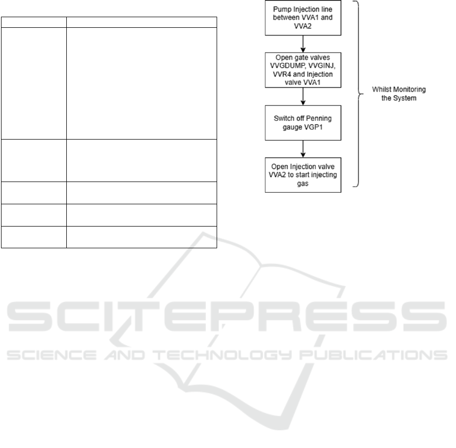
Table 2: Full interlock conditions for each device.
Device Full Interlock conditions
VVGINJ and
VVGDUMP
• All pumping groups must
be in nominal state and not
in error
• All Penning gauges must be
on and not in error (except
VPG1, not on during
injection)
• Pressure thresholds on all
Penning gauges (except
VPG1)
Dump
Pumping
Group Turbo
Ventin
g
Valve
• VVGDUMP closed, not in
error and not in warning
VVA1
• VVA3 closed, not in error
and not in warnin
g
VVA3
• VVA1 closed, not in error
and not in warning
PPINJ
• All injection valves not in
error and not in warning
The full interlocks listed in Table 2 provide
additional protection for the BGC system. On
VVGINJ and VVGDUMP, they act on valve
operation if pressures in the injection or dump
chambers are too high, or if a pumping group fails,
thereby safeguarding the beam vacuum. The full
interlock on the turbo venting valve of the dump
chamber pumping group ensures the beam pipe
cannot be accidentally vented by venting the pumping
group with VVGDUMP open. The full interlocks on
VVA1 and VVA3 protect the neon gas bottle from
being accidentally emptied through PPINJ. Finally,
the protection on PPINJ itself blocks pumping from
the injection line when faults are detected in one or
more injection valves.
The statuses used in the interlock logic that need
to be exchanged between the main and pumping
group controllers (pump nominal and error status, the
start interlock on the intermediate valve and the start
interlock on the pumping process) are transmitted via
hard-wired signals.
2.5 Operation and Limitations
Initially, when a gas injection was required, the BGC
vacuum system was operated manually by sending
separate commands to each device following a
written procedure with great care, whilst also
monitoring pressures and the status of the system as a
whole. A schematic representation of the actions that
users would have to follow to start an injection can be
seen in Figure 2.
Figure 2: Manual actions needed for injection.
As a result, only expert users with a high level of
familiarity with the system were allowed to start an
injection.
The complicated nature of the procedure meant
that the system was prone to human errors and that
starting the injection took a lot of attention and work.
To make the whole process more reliable,
efficient and accessible for new users, it was proposed
to develop a system that could automatically handle
the gas injection.
3 AUTOMATION OF THE GAS
INJECTION
The objective of the automated control system is to
execute the gas injection sequence described in
Section 2.5, as well as returning the instrument to its
initial stand-by state following an injection. In
addition, the process must be able to recover from
equipment failures and react to detected risks to the
LHC beam pipe (such as detected high pressures),
returning the instrument to the safest possible
conditions. Furthermore, the control system must
prioritise machine safety, ensure reliability and
reduce operational time and user effort.
3.1 Implementation of the Automatic
Injection Process
Process Control with Vacuum Framework is achieved
by creating a new, instantiable, control type, which will
take control of all required equipment instances
according to the desired logic. The automated control
Automated Process Control for the Beam Gas Curtain Vacuum System at CERN
285
logic is implemented as a finite state machine (FSM)
in the main PLC. All BGC devices that are part of the
automatic injection scope are forced to automatic mode
and are sent automatic commands by the process.
The status of the instrument during the automatic
injection is monitored by process interlocks (which
will be described in a later section).
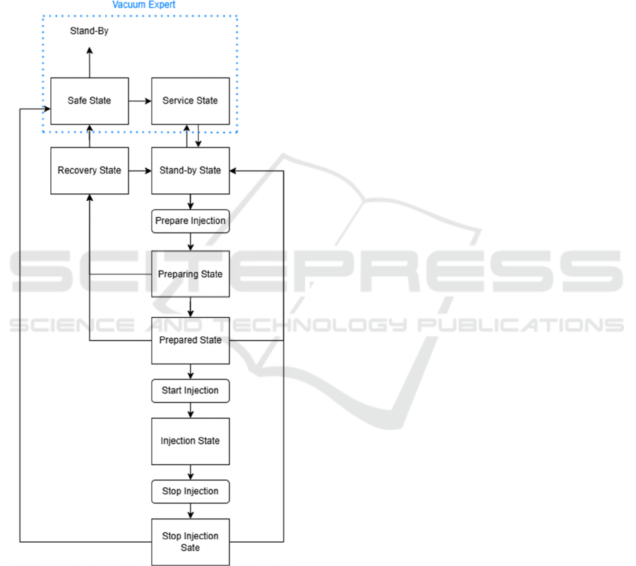
The FSM states correspond to the stages of the
injection cycle and can be seen in Figure 3. The
functions of these states are described below:
Figure 3: Automated injection FSM.
Stand-by: Default operational state (when not
injecting) where all valves are forced closed.
Awaits a “Prepare” command to proceed.
Preparing: Injection line is evacuated with
PPINJ, gate valves are opened, Penning gauge
VPG1 is turned off, VVA1 is opened.
Prepared: System is ready for injection. If
“Start Injection” command is not issued within
10 minutes, returns to Stand-by automatically
through Recovery.
Injection: VVA2 opens to inject the gas curtain.
Stops on user command or automatically after
20 hours, transitioning to Stopping Injection. If
process conditions are breached or an actuator
failure is detected, also transitions to Stopping
Injection.
Stopping Injection: All valves close, injection
line is pumped, VPG1 is reactivated. Returns to
Stand-by if successful, or to Safe if the process
conditions were breached or an actuator failure
was detected.
Recovery: Triggered if process conditions are
breached or an actuator failure is detected
during Preparing or Prepared. Actuators are
driven to safe positions before moving to Safe.
Safe: All actuators are forced to their safest
state. Can only be exited by a vacuum expert.
Default state on PLC startup.
Service: Expert-only state for manual control
and maintenance. No automatic commands are
sent to the devices.
Whilst the injection is exclusively performed
using the automatic process described above, experts
also have the option to activate manual control
through a specific command. This will allow them to
individually set devices to manual mode and perform
manual operations. Manual control is mostly used
whilst the instrument is in the Service state for
operations such as leak detections.
3.2 Process Interlocks and State-Based
Safety
Failures or hazards during the automatic injection are
detected by using process interlocks. Process
interlocks are conditions applied to the states of the
process. If the conditions are not met, the process will
either not be able to start or will move from the
current state to the Safe state in a controlled manner.
As the vacuum levels and equipment states in the
BGC chambers will differ based on the operational
state of the instrument, different sets of process
interlocks exist:
Start Process Interlocks: act during the Stand-
by state of the process and, if not satisfied, do
not allow the process to move to the preparing
state.
ICINCO 2025 - 22nd International Conference on Informatics in Control, Automation and Robotics
286
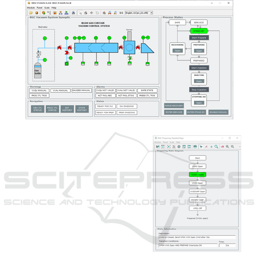
Figure 4: New BGC User Interface
Prepare Process Interlocks: act during the
Preparing and Prepared states and, if not
satisfied, move the process to the Recovery
state and then to the Safe state.
Injection Process Interlocks: act during the
Injecting state and if not satisfied, move the
process to the Stopping Injection state and then
to the Safe state.
The process interlocks are calculated based on a
set of pressure values and device statuses.
The device interlocks described in section 2.4.2
are still active even during the automatic injection,
protecting the integrity of the beam vacuum by acting
on individual devices, whilst process interlocks
protect the overall procedure.
3.3 New User Interface
For users to send the needed commands and to
monitor the system in the context of the automatic
injection, a new user interface was developed, which
can be seen in Figure 4.
On the right side of the main panel, the FSM for
the automatic injection can easily be monitored and
commands can be sent, with only two button presses
needed to start a gas injection. Some of the states
shown in the “Process States” box on the SCADA
main screen have internal steps that can be viewed in
the detailed steps panels such as the one shown in
Figure 5.
Figure 5: Preparing state detailed panel.
Various statuses, warnings and alarms are also
visible on the UI. Particularly important are the
alarms, which are configured to send an SMS
notification to predetermined vacuum experts when
triggered, so that action can be taken promptly.
Panels to monitor the status of both process
(Figure 6) and device interlocks are also available and
can be very useful for the users to better understand
what may be blocking the gas injection.
Automated Process Control for the Beam Gas Curtain Vacuum System at CERN
287
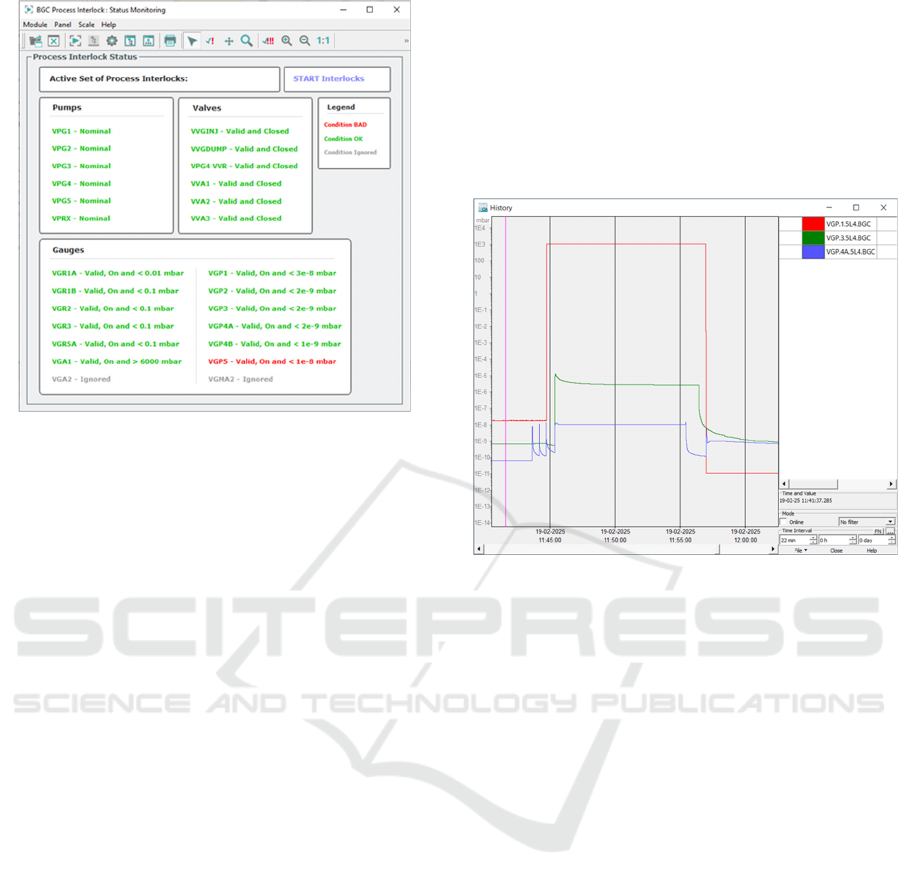
Figure 6: Process interlocks details panel.
3.4 Testing and Installation
A testing checklist was produced after identifying all
potential failures and hazardous conditions the
process needed to handle, as well as the general
functionalities required for automatic injection.
The checklist was used to thoroughly test the full
control chain by running the code on a virtual PLC
using the Siemens PLCSim Advanced software
(Siemens, 2022) connected to a local SCADA
instance. All the controlled devices were simulated
within the PLC by writing custom code.
The installation and commissioning of the new
control process along with the newly developed
control crate for the main PLC took place during
YETS 2024/25 in three stages of commissioning:
1. Device consistency across the whole control
chain was ensured, from SCADA to
hardware, by individually actuating each
device and monitoring its actual status on the
field.
2. All device interlocks were validated by
manually triggering each condition using
simulators and jump wires, ensuring the
control system responded correctly. These
simulators mimicked the behaviour of real
components (e.g., specific resistance for
Penning gauges, relay actuation for valves)
and were used throughout the testing
process.
3. The full functionality of the automatic
injection was tested in three stages:
a. Process tests with simulators connected
to all valves.
b. Process tests with simulators connected
to gate valves only (injecting gas only in
the injection chamber).
c. Process tests injecting directly in the
LHC beam pipe with vacuum sector
valves closed (Penning gauge pressures
demonstrating a successful injection are
shown in Figure 7).
Figure 7: Penning gauge pressures during test injection in
the LHC beam pipe (1E3 mbar value indicates the Penning
gauge is off).
The different features introduced with the
automated injection were tested by manually
introducing failures and checking that the instrument
recovered as expected. This was achieved by using
simulators to trigger process interlocks such as high
pressures in some of the gauges and incorrect valve
positions or error statuses.
Commissioning reports documenting the results
of all performed tests were produced, uploaded to
CERN’s internal repository, and are readily available
for consultation (Cantu, 2025).
The new injection control system was
successfully handed over for operations to the Beam
Instrumentation group at CERN together with a user
manual containing all necessary information (Cantu,
2024).
4 CONCLUSIONS
The development and deployment of the automated
vacuum control system for the BGC marks a
significant advancement in its safe and reliable
operation. The initial manually operated system,
while functional, was labour-intensive, prone to
ICINCO 2025 - 22nd International Conference on Informatics in Control, Automation and Robotics
288

human error due to its complexity and difficult for
new users to become familiarised with. By applying
industrial automation principles, the injection process
has been transformed into a robust, streamlined
procedure requiring minimal user intervention.
The use of a PLC-based finite state machine,
tightly integrated with CERN’s Vacuum Framework
and supervised via a purpose-built user interface,
ensures consistent and reproducible operation.
Device and process-level interlocks provide a dual
layer of protection, safeguarding the accelerator
infrastructure and the injection process itself. The
thorough validation strategy, including simulated
fault scenarios and staged commissioning, has
demonstrated the system’s capacity to handle
operational anomalies gracefully and has been fully
documented with commissioning and testing reports.
Following deployment during YETS 2024/25, the
system was handed over to the Beam Instrumentation
group for routine use. Users have reported that the
system significantly reduces operational complexity,
improves reliability and saves time. Positive feedback
has highlighted the clarity of the user interface, the
robustness of the automation, and the reduction in
manual interventions required to perform an
injection.
REFERENCES
Ady, M., & Sequeiro, C. C. (2022, December). BGC
schematics for discussion. In EDMS.
https://edms.cern.ch/document/2489128/1
Antoniotti, F., Kopylov, L., Mikheev, M., Gomes, P.,
Boccioli, M., Merker, S., Blanchard, S., & Pereira, H.
(2014). Developments on the SCADA of CERN
Accelerators Vacuum. In 14th International
Conference on Accelerator & Large Experimental
Physics Control Systems. https://cds.cern.ch/
record/1977437
Cantu, L. (2024). BGC Automated Process User Manual. In
EDMS. https://edms.cern.ch/document/2757469/5
Cantu, L. (2025). BGC Automated process testing and
installation. In EDMS. https://edms.cern.ch/
document/3174228/1
Chatzigeorgiou, N., & Kuhn, J. (2024, April). EDA-04939-
V1-0 v.0: Piezo Gauge Controller Crate. In EDMS.
https://edms.cern.ch/item/EDA-04939-V1-0/0
Ferreira, R., Blanchard, S., Pigny, G., Vestergard, H., &
Gomes, P. (2016). Consolidation of the controls for
turbo-molecular pumping groups at CERN's particle
accelerator complex. In 24th Mediterranean
Conference on Control and Automation (MED),
Athens, Greece, 2016, 961-966, doi: 10.1109/
MED.2016.7535968.
Rocha, A., Amador, I., Blanchard, S., Fraga, J., Gomes, P.,
Pigny, G., Poulopoulou, P., & Lima, C. (2019).
Vacuum Controls Configurator: a web based
configuration tool for large scale vacuum control
systems. In 17th Int. Conf. on Acc. and Large Exp.
Physics Control Systems ICALEPCS2019.
https://doi.org/10.18429/JACoW-ICALEPCS2019-
MOPHA123
Salehilashkajani, A., Zhang, H. D., Ady, M., Chritin, N.,
Forck, P., Glutting, J., Jones, O. R., Kersevan, R.,
Kumar, N., Lefevre, T., Marriott-Dodington, T.,
Mazzoni, S., Papazoglou, I., Rossi, A., Schneider, G.,
Sedlacek, O., Udrea, S., Veness, R., & Welsch, C. P.
(2022). A gas curtain beam profile monitor using beam
induced fluorescence for high intensity charged particle
beams. Applied Physics Letters, 120(17).
https://doi.org/10.1063/5.0085491
Sequeiro, C. C., Ady, M., Bregliozzi, G., Chatzigeorgiou,
N., Churchman, A. R., Kersevan, R., Lefevre, T.,
Mazzoni, S., Pigny, G., Rossi, A., Sameed, M.,
Schneider, G., Sedlacek, O., Sidorowski, K., Pelaez, C.
V., Veness, R., Zygaropoulos, L., Stringer, O., Webber-
Date, A., . . . Udrea, S. (2024). Beam gas curtain
monitor: Vacuum studies for LHC integration and
operation. Physical Review Accelerators and Beams,
27(4). https://doi.org/10.1103/physrevaccelbeams.
27.043201
Siemens. (2022). PLCSim Advanced (V5.0) [Software].
Tzoganis, V., & Welsch, C. (2013). Alignment of a Nozzle-
Skimmer system for a non invasive gas jet based beam
profile monitor. IBIC 2013: Proceedings of the 2nd
International Beam Instrumentation Conference, 803–
806. https://epubs.stfc.ac.uk/work/10855638
Zygaropoulos, L. (2022). Beam Gas Curtain Vacuum
Control System Technical Specifications. In EDMS.
https://edms.cern.ch/document/2757469/4
Zygaropoulos, L., & Wickham, J. M. (2024, October).
EDA-04947-V1-0 v.0: R2E Local Crate. In EDMS.
https://edms.cern.ch/item/EDA-04947-V1-0/0.
Automated Process Control for the Beam Gas Curtain Vacuum System at CERN
289
