
3D Hand-Eye Calibration for Collaborative Robot Arm:
Look at Robot Base Once
Leihui Li
1
, Lixuepiao Wan
1
, Volker Krueger
2
and Xuping Zhang
1,∗
1
Department of Mechanical and Production Engineerin, Aarhus University, Denmark
2
Department of Computer Science, Lund University, Lund, Sweden
Keywords:
Hand-Eye Calibration, 3D Vision, Collaborative Robot, Robot Arm.
Abstract:
Hand-eye calibration is a common problem in the field of collaborative robotics, involving the determination of
the transformation matrix between the visual sensor and the robot flange to enable vision-based robotic tasks.
However, this process typically requires multiple movements of the robot arm and an external calibration
object, making it both time-consuming and inconvenient, especially in scenarios where frequent recalibration
is necessary. In this work, we extend our previous method which eliminates the need for external calibration
objects such as a chessboard. We propose a generic dataset generation approach for point cloud registration,
focusing on aligning the robot base point cloud with the scanned data. Furthermore, a more detailed simulation
study is conducted involving several different collaborative robot arms, followed by real-world experiments in
an industrial setting. Our improved method is simulated and evaluated using a total of 14 robotic arms from 9
different brands, including KUKA, Universal Robots, UFACTORY, and Franka Emika, all of which are widely
used in the field of collaborative robotics. Physical experiments demonstrate that our extended approach
achieves performance comparable to existing commercial hand-eye calibration solutions, while completing
the entire calibration procedure in just a few seconds.
1 INTRODUCTION
3D vision systems, particularly those utilizing point
cloud data, provide detailed geometric surface in-
formation that enables comprehensive spatial under-
standing (Munaro et al., 2016). This capability has
significantly advanced modern manufacturing sys-
tems (Wang et al., 2021, 2017), especially in the
fields of collaborative robot and automated opera-
tions (Robinson et al., 2023; Halme et al., 2018).
Furthermore, the integration of perception sensors
with robotic manipulators has greatly enhanced au-
tomation applications that require vision-based intel-
ligent control and manipulation (Zhou et al., 2021b;
Ten Pas et al., 2017; Zhou et al., 2021a). A fun-
damental problem in collaborative robot is establish-
ing accurate coordination between the sensing system
(eye) and the tool center point (hand) (Horaud and
Dornaika, 1995; Jiang et al., 2022; Enebuse et al.,
2021). This coordination, known as hand-eye cali-
bration, determines the spatial transformation, which
consists of both translation and rotation. Widely
∗
Corresponding author
used methodologies (Enebuse et al., 2021, 2022; Wi-
jesoma et al., 1993) typically depend on specialized
calibration equipment and complex procedures, creat-
ing practical limitations in dynamic industrial settings
where systems require frequent recalibration. In this
paper, we aim to achieve fast and effective hand-eye
calibration through 3D vision.
Calibration targets in conventional hand-eye cal-
ibration are essential components (Tsai et al., 1989;
Strobl and Hirzinger, 2006), with checkerboards and
circles being the most common standard patterns
(Mallon and Whelan, 2007). By executing multi-
ple collaborative robot arm movements while acquir-
ing corresponding images, the homogeneous trans-
form equation is constructed and solved to estimate
the hand-eye transformation (Wang and Song, 2024).
Such conventional target-based approaches have in-
herent limitations: mandatory manual integration of
calibration targets, inevitably approximate solutions
due to their nonconvex nature (Wu et al., 2020), and
multiple robot movements for data collection that sig-
nificantly increase time consumption (Zhou et al.,
2023; Allegro et al., 2024; Ma et al., 2018).
To address challenges in traditional hand-eye cal-
Li, L., Wan, L., Krueger, V. and Zhang, X.
3D Hand-Eye Calibration for Collaborative Robot Arm: Look at Robot Base Once.
DOI: 10.5220/0013738500003982
Paper published under CC license (CC BY-NC-ND 4.0)
In Proceedings of the 22nd International Conference on Informatics in Control, Automation and Robotics (ICINCO 2025) - Volume 2, pages 333-341
ISBN: 978-989-758-770-2; ISSN: 2184-2809
Proceedings Copyright © 2025 by SCITEPRESS – Science and Technology Publications, Lda.
333
FoV
FoV
FoV
FoV
𝑇
𝑇
𝑇
? 𝑇
?
𝑇
𝑇
𝑇
𝑇
𝑇
𝑇
?
𝑇
?
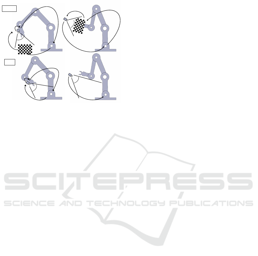
Eye-to-hand calibrationEye-in-hand calibration
Ours
Classic
Figure 1: Our proposed hand-eye and the traditional cali-
bration that needs the external calibration objects.
ibration, we build on our previous work (Li et al.,
2024), which retains user-friendliness by eliminat-
ing additional calibration targets and using the robot
base as a unified target, enabling rapid calibration.
In this paper, a generic dataset generation method is
proposed to make our approach applicable to a wide
range of collaborative robots. Additionally, 14 robotic
arms are used in the simulation to thoroughly evaluate
the robustness and accuracy of our method, demon-
strating its feasibility. Finally, a physical experiment
compares our method with a commercial hand-eye
calibration solution, demonstrating its practical appli-
cability.
Our main contributions are as follows:
1. We improve and develop a generic dataset genera-
tion method: in addition to capturing point clouds
around the robot base on hemispheres with vary-
ing radii, we also simulate realistic robot poses by
exploring diverse joint angle combinations.
2. A total of 14 collaborative robot arms from 9
brands are included in our study, each contribut-
ing 900 hand-eye calibration results. Individual
and aggregated results are analyzed, demonstrat-
ing the approach’s generalizability.
3. Real-world experiments are conducted in an in-
dustrial setting, where our proposed method is
compared with a commercial calibration setup.
Our method is validated using both single and
multiple joint configurations, demonstrating its
effectiveness and comparable performance.
2 RELATED WORK
Hand-eye calibration is a prerequisite for vision-
guided robotic manipulation systems using collabo-
rative robot arms (Hong and Ha, 2025), and the ac-
curacy of this calibration fundamentally determines
the subsequent precision of vision-based control and
manipulation within the system. To compute the un-
known transformation between a robot end-effector
and a camera, the methodological approaches to ad-
dressing hand-eye calibration can be categorized into
(Enebuse et al., 2021): solving homogeneous trans-
form equations, reprojection error minimization tech-
niques, and learning-based methods.
The conventional equation formulations can be
represented as (Zhu et al., 2024):AX = X B (Shiu and
Ahmad, 1987) or AX = Y B (Zhuang et al., 1994).
The former approach determines the hand-eye ma-
trix X through multiple sets of robot movements.
To eliminate error propagation inherent in this for-
mulation and improve noise sensitivity, Zhuang and
Shiu (Zuang and Shiu, 1993) proposed a sequential
method for solving matrix X . Recently, Ma et al.
(Ma et al., 2016) proposed novel probabilistic ap-
proaches that extend the Batch method to filter out-
lier data. The second equation seeks to simultane-
ously determine both the hand-eye matrix X and the
transformation matrix Y from the robot base to the
world coordinate. To solve this equation, many solu-
tion strategies utilize linear least-squares minimiza-
tion combined with iterative optimization schemes
(Tabb and Ahmad Yousef, 2017). In response to these
approaches, Ha (Ha, 2022) proposed a probabilistic
framework that elucidates the ambiguous aspects of
existing methods by revealing their underlying as-
sumptions about system noise. An alternative ap-
proach leverages reprojection error minimization for
hand-eye calibration. Based on this principle, Kenji
and Emanuele (Koide and Menegatti, 2019) proposed
a hand–eye calibration method that minimizes repro-
jection error via pose graph optimization, allowing ro-
bust estimation across various camera models. How-
ever, these conventional methods and their deriva-
tive approaches typically require either multiple robot
movements (at least two), additional calibration tar-
gets, or suffer from high algorithmic complexity and
extended computational time.
To overcome the limitations of conventional ap-
proaches, learning-based methodologies have been
progressively incorporated into hand-eye calibration
procedures. Hua and Zeng (Hua and Zeng, 2021)
established coordinate transformation relationships
through neural network training, achieving enhanced
grasping accuracy even under the influence of noise
ICINCO 2025 - 22nd International Conference on Informatics in Control, Automation and Robotics
334

perturbations. In constrained surgical scenarios, Krit-
tin et al. (Pachtrachai et al., 2021) estimated hand-eye
transformation through a deep convolutional network,
leveraging temporal information between frames and
kinematic data without requiring calibration objects.
Bahadir et al. (Bahadir et al., 2024) proposed Con-
tinual Learning-based approaches that enable pro-
gressive extension of the calibration space without
complete retraining, while accommodating changes
in camera pose over time. Nevertheless, exist-
ing learning-based methods still present considerable
room for improvement. The associated neural net-
works exhibit high computational complexity, lim-
ited generalizability for straightforward implementa-
tion in common robotic manipulators, and in some
cases, continued dependence on external calibration
objects. Furthermore, some approaches are limited to
either eye-in-hand or eye-to-hand calibration, failing
to address both scenarios.
In comparison with the aforementioned method-
ologies, our proposed method maintains the advan-
tage of calibration-object-free operation while accom-
modating both eye-in-hand and eye-to-hand calibra-
tion configurations. By looking at the robot base, a
closed kinematic chain is established, allowing the
transformation matrix between the camera and the
robot flange to be determined straightforwardly. In
addition, we introduce a dataset generation method
for point cloud registration of the robot base, en-
hancing the generality of our approach. Simula-
tions involving 14 commonly used collaborative robot
arms, along with physical experiments comparing our
method to commercial solutions, demonstrate the ap-
plicability and effectiveness of the proposed method.
3 PROBLEM DEFINITION AND
METHODS
In vision-guided collaborative robot systems, hand-
eye calibration aims to determine the transformation
between the camera and the tool center point (eye-in-
hand) or the robot base (eye-to-hand). In eye-in-hand
calibration, the camera is mounted on the robot’s end-
effector, moving with the arm. In contrast, in eye-to-
hand calibration, the camera is fixed in the environ-
ment to observe the robot’s workspace. To formalize
this, we define the coordinate systems: the robot base
as F
b
, the tool center point as F
t
, calibration object as
F
o
, and the camera as F
c
.
3.1 Eye-in-Hand Calibration
In the eye-in-hand configuration, the camera is rigidly
mounted on the robot’s flange, as illustrated in the
first one in Figure 1. The primary objective is to
compute the rigid transformation matrix between the
camera coordinate system and the tool center point
(TCP) frame. This problem is commonly formulated
as AX = XB, where X represents the transformation to
be solved. This calibration typically requires the robot
to move to multiple poses while observing a calibra-
tion target. Specifically, it can be expressed as
b
t
T
−1
i
b
t
T
j
t
c
T =
t
c
T
c
o
T
i
c
o
T
−1
j
(1)
where i and j denote two distinct robot poses from the
set of calibration measurements, and
b
t
T represents the
transformation matrix from the frame of the tool cen-
ter point to the robot base coordinate system.
b
t
T can
be computed through forward kinematics,
t
c
T is the
unknown hand-eye transformation matrix to be deter-
mined, and
c
o
T denotes the transformation from the
calibration object frame to the camera frame.
3.2 Eye-to-Hand Calibration
In the eye-to-hand configuration, the camera is
mounted at a fixed position within the workspace, ex-
ternal to the robot arm. This setup allows the camera
to maintain a static, global viewpoint while the robot
manipulator performs its movements. The primary
objective of eye-to-hand calibration is to determine
the rigid transformation matrix between the camera
coordinate system and the robot base coordinate sys-
tem. Through multiple movements of the calibration
board at the robot arm’s end-effector, the mathemati-
cal relationship can be established:
t
b
T
−1
i
t
b
T
j
b
c
T =
b
c
T
c
o
T
i
c
o
T
−1
j
(2)
where
b
c
T is the unknown transformation from the
camera coordinate system to the robot base coordinate
system to be calculated, and
c
o
T denotes the transfor-
mation from the camera frame to the observed cali-
bration target, measured at different robot poses.
3.3 Look at Robot Base Once
The proposed methodology eliminates the need for a
dedicated calibration object by directly observing the
robot base, as illustrated in the second setup in Fig-
ure 1. Given the 3D data of the robot base, its 6D pose
can be estimated, allowing the determination of the
transformation matrix between the camera coordinate
3D Hand-Eye Calibration for Collaborative Robot Arm: Look at Robot Base Once
335
system and the robot base coordinate system. This ap-
proach can be further extended to compute the trans-
formation matrix between the TCP coordinate system
and the camera coordinate system.
Given the captured robot base point cloud P =
{p
i
∈ R
3
|i = 1 . . . n} and the reference model point
cloud Q = {q
j
∈ R
3
| j = 1. . . m}, the objective of
registration is to find the optimal rigid body trans-
formation parameters: an orthogonal rotation matrix
R ∈ SO(3) and translation vector t ∈ R
3
that minimize
the error between the transformed actual point cloud
and the reference model point cloud. The optimiza-
tion objective can be expressed as
min
R,t
n
∑
i=1
m
min
j=1
∥p
i
− (Rq
j
+t)∥
2
(3)
where ∥p
i
− (Rq
j
+t)∥
2
is the Euclidean distance be-
tween the acquired point cloud and the reference point
cloud of robot base. Due to a scale mismatch between
the reference model and the acquired data, a pre-
transformation of the reference data, denoted
re f
′
re f
T, is
applied. The registration module provides the trans-
formation
c
re f
′
T, leading to the formulation in Eq. 4.
c
re f
T =
c
re f
′
T
re f
′
re f
T (4)
b
c
T =
c
re f
T
−1
(5)
Here, the frame of the reference data is aligned with
the frame of the robot base in the real world, which
gives Eq. 5. For eye-in-hand calibration, each move-
ment forms a closed kinematic chain as
I =
b
t
T
t
c
T
c
b
T (6)
The transformation matrix
t
c
T therefore can be ob-
tained by performing the transformation as
t
c
T =
b
t
T
−1 c
b
T
−1
(7)
The eye-in-hand setup is more computationally
challenging due to the moving camera frame, whereas
in eye-to-hand calibration,
b
c
T can be estimated
straightforwardly using a point cloud registration
module. Therefore, we adopt the eye-in-hand con-
figuration for experimental validation to demonstrate
the robustness of our approach.
The main challenge lies in generating a dataset
of robot base point clouds for registration training,
where both the source data (captured point clouds)
and the target data (reference model) are represented
as point clouds. We begin by capturing the robot
base through simulated 3D camera views positioned
around a sampled hemisphere centered at the base ori-
gin. Additionally, to enhance realism, we augment the
dataset by simulating valid robot poses based on joint
constraints, reflecting realistic configurations seen in
actual applications. Both datasets are used for train-
ing the point cloud registration network.
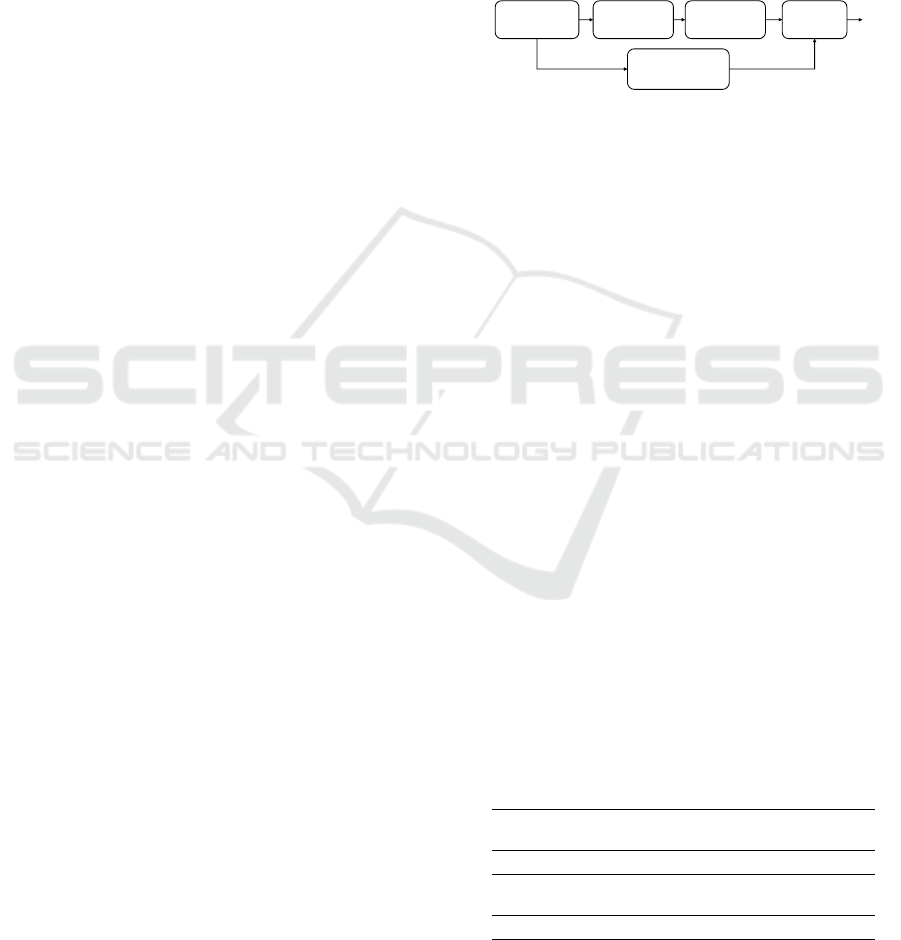
The flowchart of our proposed method is illus-
trated in Figure 2, where the first step involves mov-
ing the robot arm to position the robot base within
the camera’s field of view. Given the
c
b
T, which can
be estimated by the point cloud registration module,
and
b
t
T, provided by forward kinematics, the
t
c
T can
finally be estimated as the result of the hand-eye cali-
bration.
𝑇
𝑇
Camera-to-Base
Movement
Base Point
Cloud
Acquisition
Point Cloud
Registration
Collaborative Robot
Configuration
Hand-Eye
Calibration
𝑇
Figure 2: Flowchart of the developed hand-eye calibration.
4 EXPERIMENTS
4.1 Preparation and Experiment Setup
The robot arms used in our simulation environment
are listed in Table 2. We utilize PyBullet as the sim-
ulation platform, where the robot arm is represented
in URDF and OBJ file formats for loading and gen-
erating the trainable dataset. PREDATOR (Huang
et al., 2021), a registration network designed for low-
overlap point clouds, is adopted in our study, fol-
lowed by an ICP refinement step. This combination,
as shown in our previous work (Li et al., 2024), im-
proves robustness under partial overlap between the
captured data and the robot base reference model.
In our study, the raw point clouds are used with-
out background filtering. The camera is positioned on
a virtual hemisphere with radii of 0.5 and 0.7 meters,
capturing data from multiple perspectives to simulate
real 3D camera acquisition. The final dataset, avail-
able online, which is combined with realistic simu-
lated acquisition data, is used for training and is de-
tailed in Table 1. Five random transformation ma-
trices are applied to the captured data, and the point
clouds are downsampled with a 2 mm voxel size.
Table 1: The size of the dataset for registration training.
FR3 Gen3 iiwa 7 iiwa 14
CRX
-10iA
CRX
-5iA
UR10e
1224 1074 810 954 1230 1026 816
UR5e xArm6 xArm7
CRB
15000
HC10 EC66 EC63
1110 756 1140 768 1104 1014 1140
ICINCO 2025 - 22nd International Conference on Informatics in Control, Automation and Robotics
336
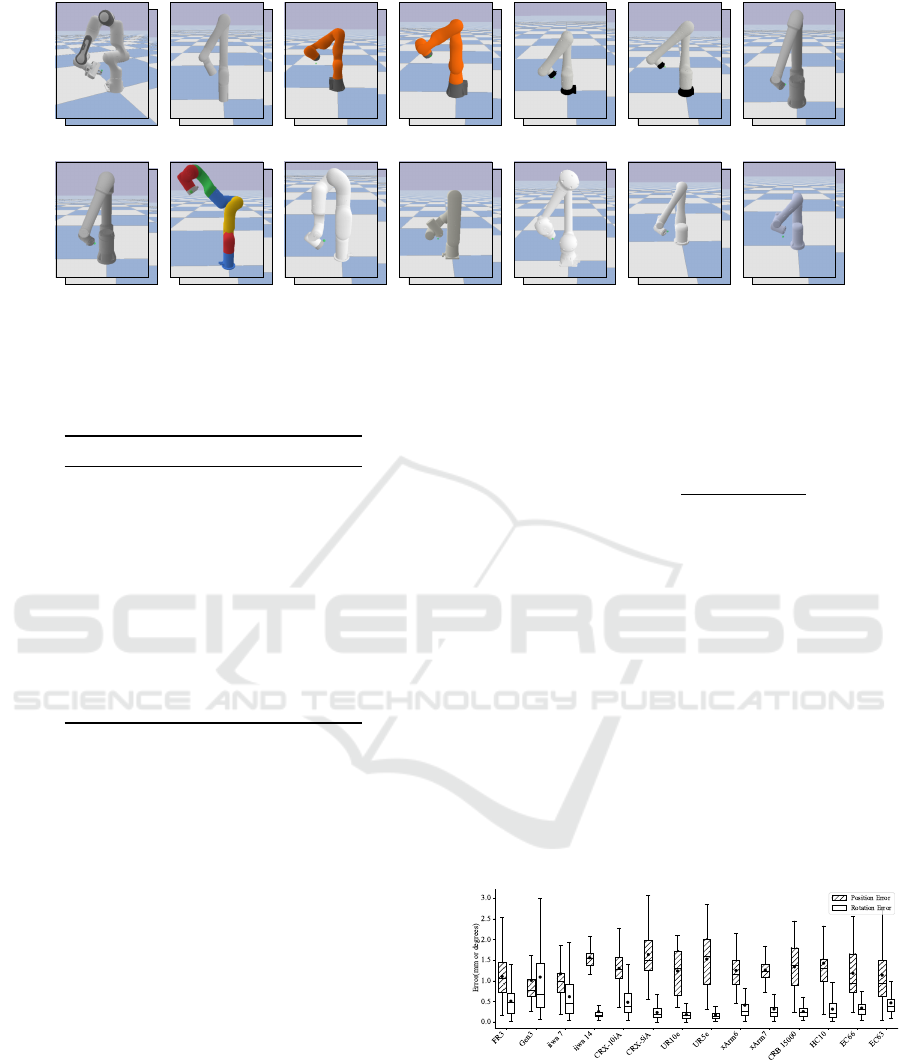
FR3 Gen3 iiwa7 iiwa14 CRX-5iA CRX-10iA UR10e
UR5e xArm7
xArm6
CRB15000 HC10 EC66 EC63
Figure 3: Visualization of randomly selected robot base-looking poses for various robotic manipulators, with one representa-
tive joint configuration shown.
Table 2: The collaborative robot arm used in our study.
Index Robot Arm Manufacturer
1 FR3 Franka Robotics
2 Gen3 Kinova
3 iiwa 7 KUKA
4 iiwa 14 KUKA
5 CRX-5iA FANUC
6 CRX-10iA FANUC
7 UR10e Universal Robots
8 UR5e Universal Robots
9 xArm6 UFACTORY
10 xArm7 UFACTORY
11 CRB 15000 ABB
12 HC10 Yaskawa Motoman
13 EC66 Elite Robots
14 EC63 Elite Robots
4.2 Experimental Results
We evaluate the proposed approach in simulation,
where the ground-truth transformation between the
camera and TCP frame is known. For each robot
arm, 30 random poses are generated within realis-
tic joint angle limits to ensure kinematic feasibility,
where the camera looks at the robot base and the joint
rotations differ by at least 20 degrees to avoid near-
duplicate configurations, as shown in Figure. 3. In
all selected poses, the robot base remains within the
camera’s field of view to satisfy the method’s require-
ments. At each pose, the end-effector-mounted 3D
camera captures multiple base scans, each yielding an
individual calibration result.
The final calibration result is obtained by averag-
ing the rotation matrices in quaternion space and the
translation vectors in Euclidean space. Ideally, the
hand-eye calibration results obtained from the poses
match the ground truth (
¯
R and
¯
t), meaning the RTE
and RRE in translation and rotation should be zero,
as
RTE = ∥t −
¯
t∥
2
(8)
RRE = arccos
trace(R
T
¯
R) − 1
2
(9)
In addition to 30 unique base-looking poses for
each robotic arm, we captured 30 repeated scans per
pose, resulting in 900 calibration results per robot.
The calibration performance across all robot arms is
analyzed. As shown in Figure 4, it illustrates the av-
erage deviations in position and rotation errors, and
reports the median and standard deviation for each
robot. According to the results, the positional devi-
ation for all poses remains below approximately 1.5
mm, and most rotational deviations are under 0.5
◦
.
The largest deviation is observed in the Gen3 robot
arm. Overall, considering the point cloud voxel size
of 2 mm, the tested poses yield reliable calibration
performance, with a mean error of 1.29 mm in posi-
tion and 0.39
◦
in rotation.
Figure 4: The hand-eye calibration results calculated from
all poses for each robot arm are shown, with the mean value
represented by a black dot. In the box plot, the horizontal
line indicates the median value, while the top and bottom
edges represent the standard deviation.
At each pose, 30 sets of 3D data from the robot
base are collected, resulting in 30 calibration results.
The deviation of different poses is shown in Figure.
3D Hand-Eye Calibration for Collaborative Robot Arm: Look at Robot Base Once
337
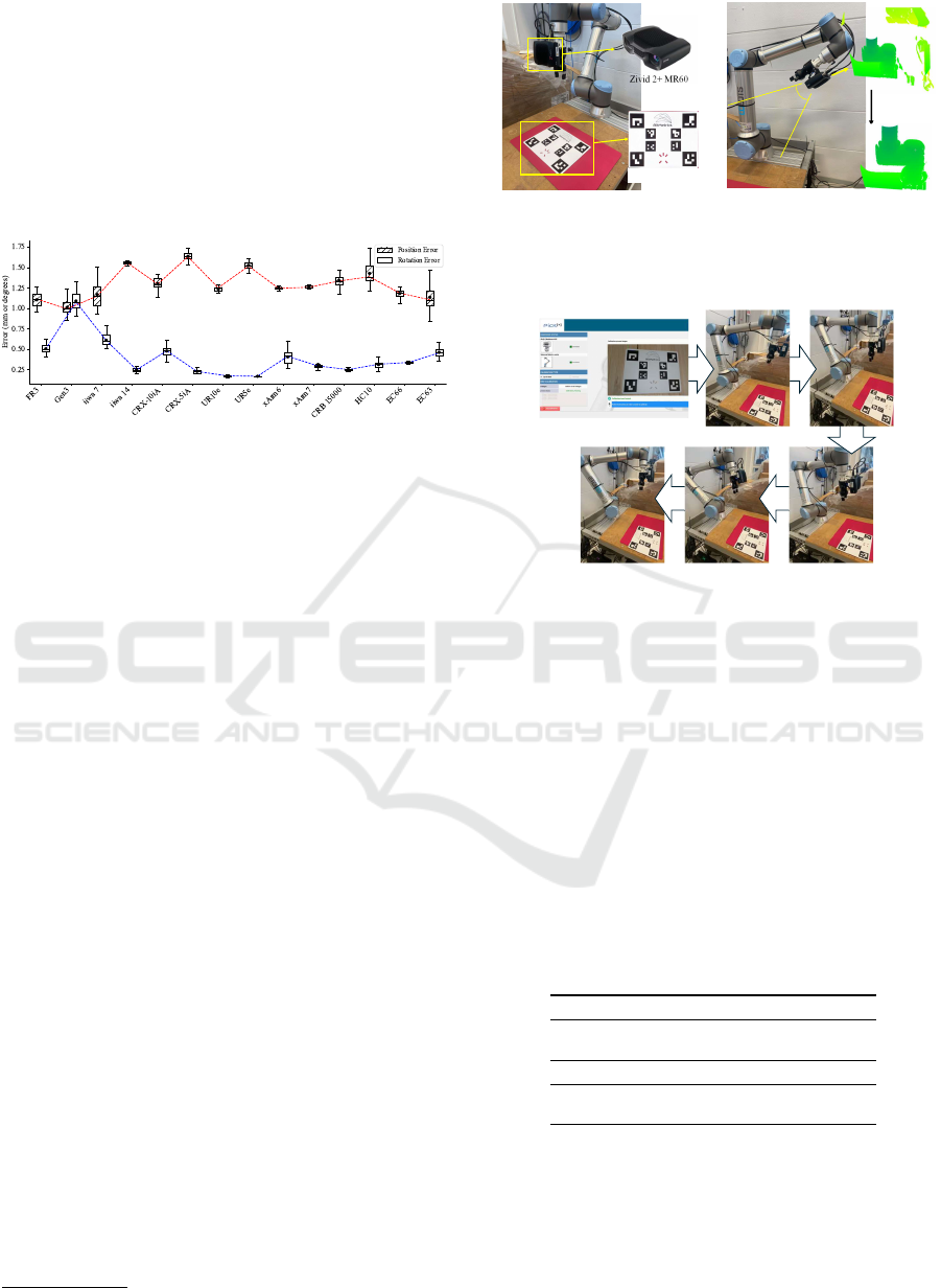
5. According to the results, the positional deviation
for each pose ranges from 1 mm to 1.6 mm, with the
largest variation observed in robot CRX-5iA. The ro-
tational deviation ranges from 0.16
◦
to 1
◦
, with the
highest occurring in the Gen3 robot. The results in-
dicate that, for the tested robot arm with different
poses, the proposed method generally achieves a sim-
ilar level of accuracy; that is, our method does not rely
on any specific pose of the robot arm.
Figure 5: The differences between poses are illustrated by
data points connected with red and blue lines, representing
positional and rotational deviations, respectively.
This deviation, observed in the simulation envi-
ronment, primarily arises from registration errors and
the density of the point clouds, including both the re-
trieved data and the standard model. However, in real-
world applications, additional factors such as cam-
era imaging inaccuracies, point cloud noise, and dis-
crepancies between the CAD model and the scanned
robot base can further contribute to calibration errors.
Therefore, real-world experiments are conducted to
compare our proposed method with current commer-
cial and mature solutions.
4.3 Real-World Experiments
The experiment is conducted on the UR10e robot
with a high-accuracy 3D camera, the Zivid 2+ MR60,
which achieves a spatial resolution of 0.24 mm at
a working distance of 60 cm and generates highly
detailed point clouds with a density of 5,000 points
per cm². Although a high-precision 3D camera was
used for real-world validation, the method is sensor-
agnostic and applicable to other 3D cameras capable
of capturing the robot base geometry. The experimen-
tal setup is shown in Figure. 6a, where a calibration
board is needed. Figure. 6b illustrates the calibration
setup, with the camera oriented toward the robot base.
We compared our method with the current com-
mercial eye-in-hand calibration solution, BM-HEC
1
,
which is based on the AX = XB formulation. The tra-
ditional calibration process was repeated four times,
as shown in Figure 7, where multiple robot move-
ments are required during each calibration. Our
1
www.bitmetrics.es
Zivid 2+ MR60
Calibration Object
Eye-in-hand calibration setup
Cropped using
axis range
constraints
Field of view
(a)
Zivid 2+ MR60
Calibration Object
Eye-in-hand calibration setup
Cropped using
axis range
constraints
Field of view
(b)
Figure 6: (a) Traditional calibration with external object and
multiple robot movements. (b) Our calibration focusing on
the robot base without external object.
BM-HEC configuration GUI
Figure 7: Traditional calibration requires multiple move-
ments to capture the calibration object from different per-
spectives.
method was also performed four times, with each in-
dividual scan producing a complete calibration result.
The calibration process typically takes an average of
2 minutes and 48 seconds, requiring 14 poses and im-
ages of the calibration board placed on the table. In
contrast, our method completes the calibration in just
a few seconds with a single pose. The average cali-
bration results, i.e., the rigid relationship between the
robot flange and the camera frame, are shown in Ta-
ble 3, where the rotation in Euler space and position
in Euclidean space are provided.
Table 3: Comparison of Eye-in-Hand Calibration with a
Commercial Calibration Solution.
Method TX (m) TY (m) TZ (m) Time
BM-HEC -0.054 -0.094 0.127 2m48s /
per calibOurs -0.051 -0.096 0.125
Method RX (rad) RY (rad) RZ (rad) Time
BM-HEC 0.013 0.044 0.017 6s /
per calibOurs 0.014 0.044 0.019
According to the results in Table 3, The offsets
between our method and BM-HEC are 3 mm, 2 mm,
and 3 mm in terms of position, and 0.001 and 0.002 in
rotation along the X and Z axes, respectively. The off-
set along the Y-axis is nearly zero. Most importantly,
the calibration time of our proposed method is within
6 seconds, whereas the traditional method takes over
ICINCO 2025 - 22nd International Conference on Informatics in Control, Automation and Robotics
338
Pose#1 Pose#2 Pose#3 Pose#4 Pose#5 Pose#6
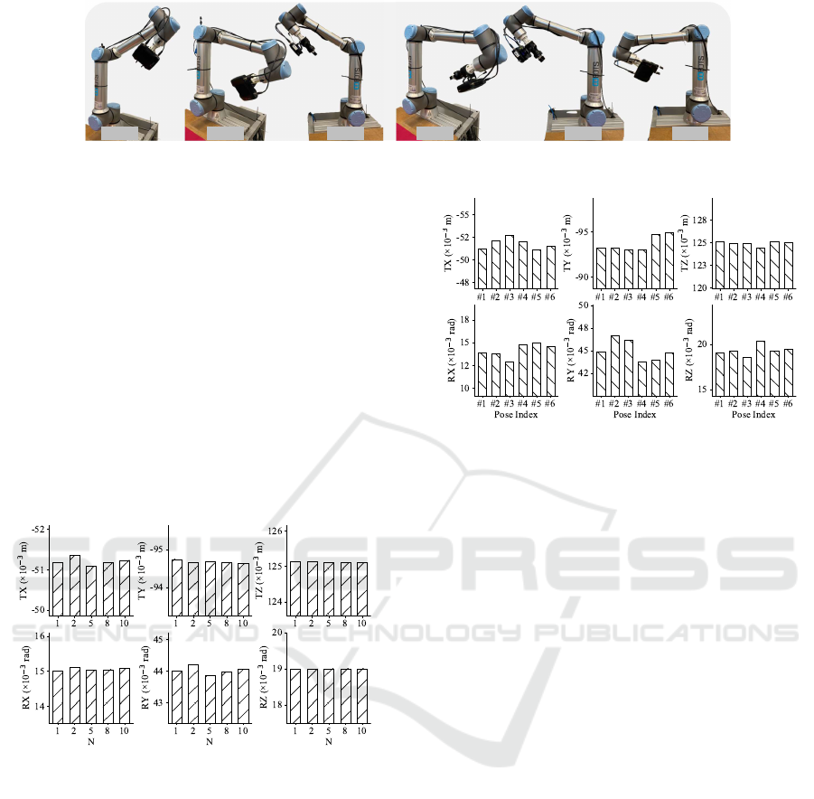
Figure 9: Different poses used in our proposed hand-eye calibration method.
2.5 minutes, requiring multiple robot movements and
a physical external calibration object.
Furthermore, given a single pose with multiple
frames captured at that pose, calibration is computed
multiple times. The results are shown in Figure. 10,
where the average of the first N result(s) is presented
for N = 1, 2, 5, 8, and 10. The results demon-
strate that the largest translation deviation along the
X-axis is approximately 0.2 mm, and the rotational
deviation around the Y-axis is about 3 × 10
−4
radi-
ans (0.019
◦
). Given a standard deviation of approxi-
mately 0.1 × 10
−3
, using additional frames results in
nearly identical calibration performance. Therefore,
our method can reliably perform hand-eye calibration
using just a single frame of 3D point cloud data.
Figure 10: Average of the first n calibrations at a single
pose.
In addition, different poses for eye-in-hand cali-
bration on the UR10e, as illustrated in Figure 9, are
validated. The results in Figure 11 show the maxi-
mum translation deviation was about 1.8 mm and the
minimum about 0.6 mm, with rotation deviations be-
tween 0.001 and 0.002 radians. These results demon-
strate that our proposed calibration method maintains
consistent performance across multiple poses. To-
gether with the large-scale evaluation on 14 collab-
orative robot models from 9 brands in simulation,
this confirms the robustness and applicability of the
method across diverse platforms.
Figure 11: Hand-eye calibration results across 6 poses.
5 CONCLUSION AND FUTURE
WORK
In this work, we extended and improved our previ-
ous method, a 3D vision-based hand-eye calibration
approach. Our learning-based framework estimates
the pose of the robot base, enabling the computation
of the transformation matrix between the robot flange
and the camera within seconds. We enhance the regis-
tration dataset by incorporating captured point clouds
from diverse perspectives and realistic robot arm con-
figurations. We conduct large-scale evaluations in-
volving 14 collaborative robot models from 9 brands,
including KUKA, ABB, and FANUC, and real-world
validation with a high-precision 3D camera on an
industrial-grade robot. These experiments confirm
that our approach matches the calibration accuracy of
commercial solutions, while greatly reducing calibra-
tion time and eliminating the need for external ob-
jects, making it broadly applicable to diverse collabo-
rative robot systems.
In future work, we will focus on enhancing usabil-
ity and long-term stability to further support deploy-
ment in diverse industrial environments.
ACKNOWLEDGMENTS
The authors thank Jialong Li for his excellent col-
laboration and patient support, everyone in RobotLab
3D Hand-Eye Calibration for Collaborative Robot Arm: Look at Robot Base Once
339

LTH for their valuable assistance, and Jungner Com-
pany for its support.
REFERENCES
Allegro, D., Terreran, M., and Ghidoni, S. (2024). Multi-
camera hand-eye calibration for human-robot collab-
oration in industrial robotic workcells. arXiv preprint
arXiv:2406.11392.
Bahadir, O., Siebert, J. P., and Aragon-Camarasa, G. (2024).
Continual learning approaches to hand–eye calibra-
tion in robots. Machine Vision and Applications,
35(4):97.
Enebuse, I., Foo, M., Ibrahim, B. S. K. K., Ahmed, H.,
Supmak, F., and Eyobu, O. S. (2021). A comparative
review of hand-eye calibration techniques for vision
guided robots. IEEE Access, 9:113143–113155.
Enebuse, I., Ibrahim, B. K. K., Foo, M., Matharu, R. S., and
Ahmed, H. (2022). Accuracy evaluation of hand-eye
calibration techniques for vision-guided robots. Plos
one, 17(10):e0273261.
Ha, J. (2022). Probabilistic framework for hand–eye and
robot–world calibration ax = yb. IEEE Transactions
on Robotics, 39(2):1196–1211.
Halme, R.-J., Lanz, M., K
¨
am
¨
ar
¨
ainen, J., Pieters, R., La-
tokartano, J., and Hietanen, A. (2018). Review of
vision-based safety systems for human-robot collab-
oration. Procedia Cirp, 72:111–116.
Hong, I. and Ha, J. (2025). Generative adversarial networks
for solving hand-eye calibration without data corre-
spondence. IEEE Robotics and Automation Letters.
Horaud, R. and Dornaika, F. (1995). Hand-eye calibra-
tion. The international journal of robotics research,
14(3):195–210.
Hua, J. and Zeng, L. (2021). Hand–eye calibration algo-
rithm based on an optimized neural network. In Actu-
ators, volume 10, page 85. MDPI.
Huang, S., Gojcic, Z., Usvyatsov, M., Wieser, A., and
Schindler, K. (2021). Predator: Registration of 3d
point clouds with low overlap. In Proceedings of the
IEEE/CVF Conference on computer vision and pat-
tern recognition, pages 4267–4276.
Jiang, J., Luo, X., Luo, Q., Qiao, L., and Li, M. (2022).
An overview of hand-eye calibration. The Interna-
tional Journal of Advanced Manufacturing Technol-
ogy, 119(1):77–97.
Koide, K. and Menegatti, E. (2019). General hand–eye
calibration based on reprojection error minimization.
IEEE Robotics and Automation Letters, 4(2):1021–
1028.
Li, L., Yang, X., Wang, R., and Zhang, X. (2024). Auto-
matic robot hand-eye calibration enabled by learning-
based 3d vision. Journal of Intelligent & Robotic Sys-
tems, 110(3):130.
Ma, L., Bazzoli, P., Sammons, P. M., Landers, R. G., and
Bristow, D. A. (2018). Modeling and calibration of
high-order joint-dependent kinematic errors for indus-
trial robots. Robotics and Computer-Integrated Man-
ufacturing, 50:153–167.
Ma, Q., Li, H., and Chirikjian, G. S. (2016). New proba-
bilistic approaches to the ax= xb hand-eye calibration
without correspondence. In 2016 IEEE international
conference on robotics and automation (ICRA), pages
4365–4371. IEEE.
Mallon, J. and Whelan, P. F. (2007). Which pattern? bias-
ing aspects of planar calibration patterns and detection
methods. Pattern recognition letters, 28(8):921–930.
Munaro, M., Rusu, R. B., and Menegatti, E. (2016). 3d
robot perception with point cloud library.
Pachtrachai, K., Vasconcelos, F., Edwards, P., and Stoy-
anov, D. (2021). Learning to calibrate-estimating the
hand-eye transformation without calibration objects.
IEEE Robotics and Automation Letters, 6(4):7309–
7316.
Robinson, N., Tidd, B., Campbell, D., Kuli
´
c, D., and Corke,
P. (2023). Robotic vision for human-robot interac-
tion and collaboration: A survey and systematic re-
view. ACM Transactions on Human-Robot Interac-
tion, 12(1):1–66.
Shiu, Y. C. and Ahmad, S. (1987). Calibration of wrist-
mounted robotic sensors by solving homogeneous
transform equations of the form ax= xb.
Strobl, K. H. and Hirzinger, G. (2006). Optimal hand-eye
calibration. In 2006 IEEE/RSJ international confer-
ence on intelligent robots and systems, pages 4647–
4653. IEEE.
Tabb, A. and Ahmad Yousef, K. M. (2017). Solving the
robot-world hand-eye (s) calibration problem with it-
erative methods. Machine Vision and Applications,
28(5):569–590.
Ten Pas, A., Gualtieri, M., Saenko, K., and Platt, R. (2017).
Grasp pose detection in point clouds. The Interna-
tional Journal of Robotics Research, 36(13-14):1455–
1473.
Tsai, R. Y., Lenz, R. K., et al. (1989). A new technique for
fully autonomous and efficient 3 d robotics hand/eye
calibration. IEEE Transactions on robotics and au-
tomation, 5(3):345–358.
Wang, G., Li, W., Jiang, C., Zhu, D., Li, Z., Xu, W.,
Zhao, H., and Ding, H. (2021). Trajectory planning
and optimization for robotic machining based on mea-
sured point cloud. IEEE transactions on robotics,
38(3):1621–1637.
Wang, X. and Song, H. (2024). One-step solving the hand–
eye calibration by dual kronecker product. Journal of
Mechanisms and Robotics, 16(10).
Wang, X. V., Wang, L., Mohammed, A., and Givehchi,
M. (2017). Ubiquitous manufacturing system based
on cloud: A robotics application. Robotics and
Computer-Integrated Manufacturing, 45:116–125.
Wijesoma, S., Wolfe, D., and Richards, R. (1993). Eye-
to-hand coordination for vision-guided robot control
applications. The International Journal of Robotics
Research, 12(1):65–78.
Wu, J., Liu, M., Zhu, Y., Zou, Z., Dai, M.-Z., Zhang, C.,
Jiang, Y., and Li, C. (2020). Globally optimal sym-
ICINCO 2025 - 22nd International Conference on Informatics in Control, Automation and Robotics
340

bolic hand-eye calibration. IEEE/ASME Transactions
on Mechatronics, 26(3):1369–1379.
Zhou, P., Peng, R., Xu, M., Wu, V., and Navarro-Alarcon,
D. (2021a). Path planning with automatic seam ex-
traction over point cloud models for robotic arc weld-
ing. IEEE robotics and automation letters, 6(3):5002–
5009.
Zhou, Z., Li, L., Wang, R., and Zhang, X. (2021b). Deep
learning on 3d object detection for automatic plug-in
charging using a mobile manipulator. In 2021 IEEE
International Conference on Robotics and Automation
(ICRA), pages 4148–4154. IEEE.
Zhou, Z., Ma, L., Liu, X., Cao, Z., and Yu, J. (2023). Si-
multaneously calibration of multi hand–eye robot sys-
tem based on graph. IEEE Transactions on Industrial
Electronics, 71(5):5010–5020.
Zhu, D., Wu, H., Ding, T., and Hua, L. (2024). Point cloud
registration-enabled globally optimal hand–eye cali-
bration. IEEE/ASME Transactions on Mechatronics.
Zhuang, H., Roth, Z. S., and Sudhakar, R. (1994). Si-
multaneous robot/world and tool/flange calibration by
solving homogeneous transformation equations of the
form ax= yb. IEEE Transactions on Robotics and Au-
tomation, 10(4):549–554.
Zuang, H. and Shiu, Y. C. (1993). A noise-tolerant algo-
rithm for robotic hand-eye calibration with or without
sensor orientation measurement. IEEE transactions
on systems, man, and cybernetics, 23(4):1168–1175.
3D Hand-Eye Calibration for Collaborative Robot Arm: Look at Robot Base Once
341
