
Sky Savers: Leveraging Drone Technology for Victim Localization
in Avalanche Rescue via Transceiver Signal Analysis
Robin Vetsch
1,3 a
, Samuel Kranz
2 b
, Tindaro Pittorino
2 c
, Peter de Baets
4
, Martial Ch
ˆ
ateauvieux
4
,
Christoph W
¨
ursch
3 d
, Daniel Lenz
3
and Sebastien Gros
1 e
1
Department of Engineering Cybernetics, Norwegian University of Science and Technology, Høgskoleringen 1, Trondheim,
Norway
2
Institute for Electronics, Sensors and Actuators, Eastern Switzerland University of Applied Sciences, Werdenbergstrasse 4,
Buchs, Switzerland
3
Institute for Computational Engineering, Eastern Switzerland University of Applied Sciences, Werdenbergstrasse 4, Buchs,
Switzerland
4
ANAVIA, Bahnhofstrasse 37, N
¨
afels, Switzerland
Keywords:
Avalanche Rescue, Victim Localization, Vertical Take-Off and Landing (VTOL) System, Avalanche
Transceiver.
Abstract:
In modern avalanche rescues, the search for buried victims is carried out primarily using a state-of-the-art
handheld transceiver. However, in situations where the rescuers do not have the necessary experience, or
if the victims are buried in areas that can be dangerous for the rescuers, e.g. due to the risk of secondary
avalanches, this search process can be time-consuming, complex and dangerous. To overcome these chal-
lenges, we propose a proof-of-concept (PoC) of a search system based on an autonomous vertical take-off
and landing (VTOL) aircraft that could significantly reduce search time, even in the case of multiple over-
lapping signal sources attributable to multiple victims or where conventional methods are not sufficiently
efficient, e.g. in the case of large-scale avalanches. Electric drones or VTOL systems cannot be used because
electro-magnetic interference (EMI) blocks the signal from the sending avalanche transceiver. By replacing
electromagnetically noisy DC motors with a turbine, we effectively reduce electro-magnetic interference in
the signal stream and demonstrate sub-meter localization accuracy under realistic field conditions. We employ
a two-stage Extended Kalman Filter (EKF) approach to estimate the stationary target coordinates. Eventually,
a VTOL system also allows for operations in adverse weather and rugged alpine terrain, greatly extending the
practical capability of search and rescue missions.
1 INTRODUCTION
On average, around 100 people die in avalanche ac-
cidents every winter in Europe (Association, 2025).
This high number of fatalities motivates the develop-
ment of an automated system to locate buried victims
as quickly as possible.
In modern avalanche rescues, the search for buried
victims is carried out primarily using commercially
available handheld avalanche transceivers (Mammut,
2024b). The clinical study conducted by Brugger
et al. (Brugger et al., 2007) showed how the use of
an avalanche transceiver or an airbag could reduce
a
https://orcid.org/0009-0007-8099-9457
b
https://orcid.org/0009-0006-6766-6458
c
https://orcid.org/0009-0005-7548-1130
d
https://orcid.org/0000-0002-1337-3477
e
https://orcid.org/0000-0001-6054-2133
the probability of mortality. Rescuers rely on these
transceivers to locate individuals by following the
strength and direction of the signals, moving closer to
the strongest signal to pinpoint the victim’s location.
Although this method can be effective, the rescuer
must be proficient in using the device and interpret-
ing the visualizations on the graphical user interface
(GUI). In scenarios where rescuers have limited or no
experience, or when there are multiple victims buried
under the avalanche, the search process can become
time consuming and complex, increasing the chance
of deadly fatalities (Falk et al., 1994).
To address these challenges, we propose a VTOL
search platform designed for fully automated opera-
tion, capable of drastically reducing victim localiza-
tion times over vast avalanche terrains. With the com-
bination of slow flight, vertical take-off and landing,
and fast cruise flight to the accident site, our system
Vetsch, R., Kranz, S., Pittorino, T., de Baets, P., Châteauvieux, M., Würsch, C., Lenz, D. and Gros, S.
Sky Savers: Leveraging Drone Technology for Victim Localization in Avalanche Rescue via Transceiver Signal Analysis.
DOI: 10.5220/0013736400003982
Paper published under CC license (CC BY-NC-ND 4.0)
In Proceedings of the 22nd International Conference on Informatics in Control, Automation and Robotics (ICINCO 2025) - Volume 1, pages 469-476
ISBN: 978-989-758-770-2; ISSN: 2184-2809
Proceedings Copyright © 2025 by SCITEPRESS – Science and Technology Publications, Lda.
469
can reach confined and remote regions that are inac-
cessible to fixed-wing aircraft or ground vehicles, thus
speeding up search operations in large areas.
As a sensor for localization, we used a commer-
cially available MAMMUT Barryvox Pulse avalanche
transceiver (Mammut, 2024a), which was integrated
as an external payload onto the VTOL system. Our
custom data analysis pipeline fuses the transceiver
output with real-time GPS and heading information
from the VTOL onboard navigation suite. As a
backup, the sensor system also had a GPS module on
board, which provided a data quality comparable to
the GPS of the VTOL system. As input signals for
the localization algorithm in this PoC, we used dis-
tance r and direction ϕ (in 15
◦
increments) data of
the transceiver device. This data is also available on
the display of the device and is used today for mate
searches by the user.
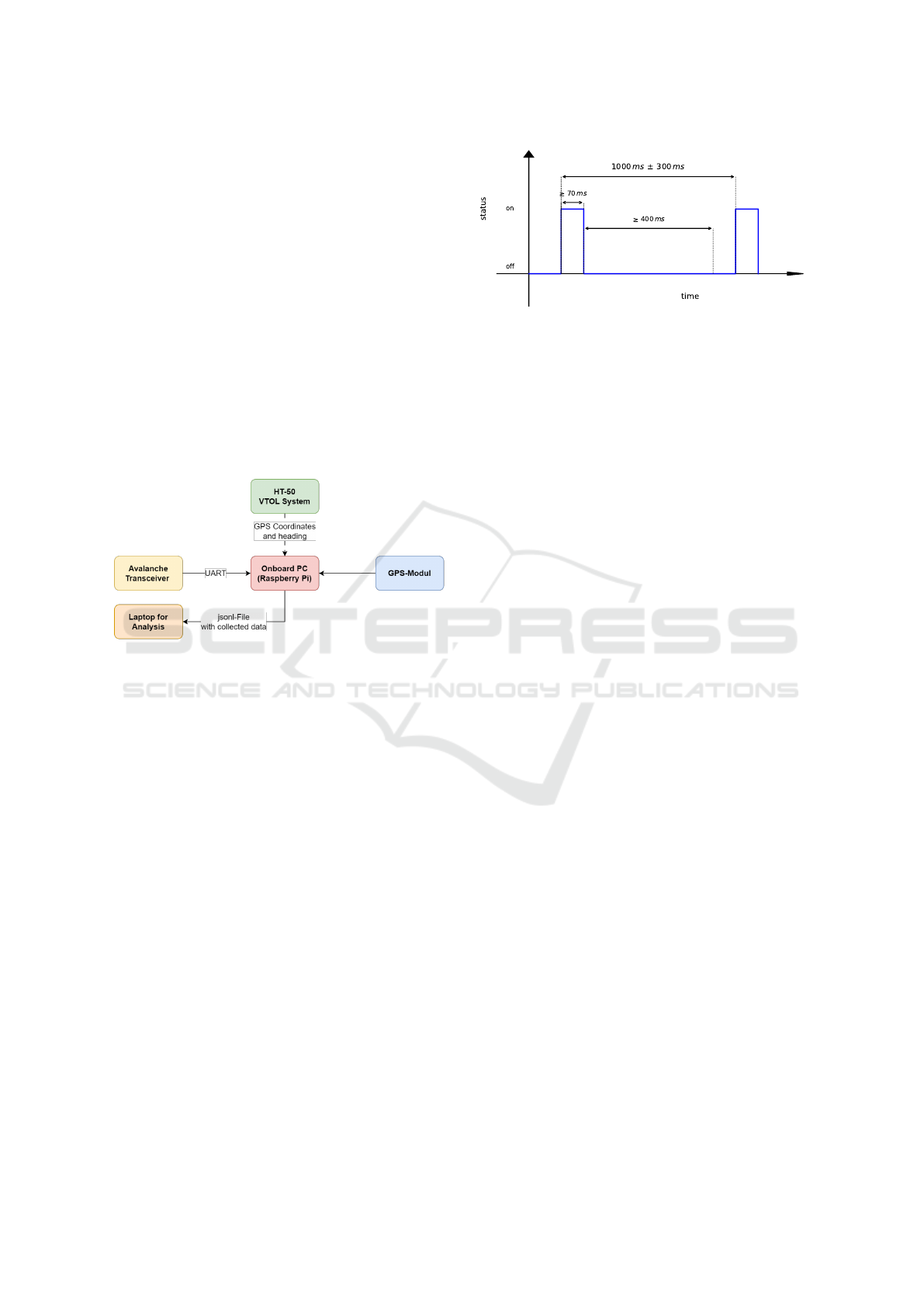
Figure 1: The proposed localization system (sensor sys-
tem) consists of a 3-axis magnetic field sensor, an MAM-
MUT Barryvox Pulse (yellow), an onboard computer for
data collection (red) and a GPS module (blue). During
flight, the VTOL system provides GPS and heading infor-
mation which is used to compare the position estimations of
the GPS module of the sensor system in blue.
1.1 Function of an Avalanche
Transceiver
An avalanche transceiver essentially consists of an ar-
rangement of three coils in the x, y and z directions, as
shown in (Ayuso et al., 2015). The device can operate
in two modes, send / transmit and search / receive.
In send mode, the coil in the x direction, which has
the highest sensitivity, and thanks to its size, gener-
ates a magnetic field. In search mode, the magnetic
field emitted by the transmitter is coupled to the re-
ceiver via the x- and y-antennas and processed on-
board. The z-antenna, which has the lowest sensitiv-
ity due to its limited length, is only used for the fine
search. The fine search is defined as a specific search
pattern (r < 5 m) that is used to locate the person as
precisely as possible, before shoveling the person out.
In send mode, the device sends a pulsed electro-
magnetic signal that is generated with an oscillation
Figure 2: EN-normed pulse signal pattern including the
minimal and maximal time length of the on- and off pe-
riod. The pulse length and the off-time between two pulses
is used for the separation of multiple targets.
frequency of f
s
= 457 kHz and is approved worldwide
for avalanche rescue. The signal is pulsed at regu-
lar intervals defined by the EN norm industry stan-
dard (ETSI, 2017), but with a unique repetition fre-
quency to distinguish multiple signals when several
transceivers transmit simultaneously. To minimize
power consumption, the frequency of the signal is
limited to approximately 1 Hz. The normed signal is
shown in Figure 2.
1.2 Related Work
Recent research efforts in the development of auto-
mated systems for avalanche rescue have increasingly
focused on the integration of sensor modalities into
unmanned aerial vehicles (UAVs), such as drones for
the rapid location of victims. However, commercial
drones often exhibit significant drawbacks when op-
erating in extreme environments, particularly with re-
gard to electro-magnetic interference caused by con-
ventional electric motors, which adversely impacts
the performance of onboard avalanche transceivers.
In addition, lithium batteries used in electric drones
exhibit a loss of capacity in the cold winter weather,
significantly limiting endurance.
A notable commercial initiative was the Powder-
Bee system, a lightweight (600g) battery-powered
drone designed for rapid search operations. Powder-
Bee was engineered to autonomously execute prede-
fined search patterns and land upon detection of a
buried victim. Despite its innovative design, the com-
pany (Bluebird Mountain Inc.) was dissolved in 2021
and the EMI challenges inherent to its commercial
platform remained unresolved (Bluebird, 2021).
Similarly, the Alcedo project from ETH Zurich
represented an early student-driven effort to develop
a foldable and easily transportable UAV for avalanche
search and rescue. The system aimed to localize
the buried victims according to the dimensions of
the avalanche supplied by the user. However, the
project did not progress beyond the prototype stages
ICINCO 2025 - 22nd International Conference on Informatics in Control, Automation and Robotics
470
due to robustness limitations and EMI issues (Alcedo,
2010).
The start-up Nivitec pursued an approach using
a DJI Matrice 210 drone (DJI, 2025) equipped with
an avalanche transceiver and a camera system. Their
concept included plans for automated navigation to
accident sites. However, the company stopped its
activities in 2020, facing challenges related to lim-
ited flight endurance and operational speed (Nivitec,
2020).
An alternative mitigation strategy is employed by
the Atlas AVALANCHE PRO system, which sus-
pends the avalanche transceiver on a flexible pole 1
to 2 meters below the UAV to physically reduce EMI.
Although this approach helps minimize interference,
the uncontrolled orientation of the transceiver com-
promises the precision of the location, leading to the
potential loss of critical positional data (ATLASUAS,
2025).
Beyond these commercial initiatives, a growing
body of academic research has advanced UAV-based
avalanche victim localization using transceiver sys-
tems. Silvagni et al. (Silvagni et al., 2017) developed
a UAV system that integrates a commercial avalanche
transceiver and thermal camera, demonstrating auto-
mated localization tested in Alpine conditions.
Azzollini et al. (Azzollini et al., 2020) pro-
posed an extremum-seeking control strategy to au-
tonomously steer a transceiver-equipped UAV toward
the strongest signal, validated through simulation and
hardware-in-the-loop tests.
The AVERLA project by Toson et al. (To-
son et al., 2021) presented a custom high-gain an-
tenna system for UAV-mounted transceiver tracking,
achieving preliminary field success despite challenges
in system miniaturization.
However, Janovec et al. (Janovec et al., 2022) re-
ported severe EMI issues between UAV electronics
and the beacon, concluding that conventional electric
UAV platforms are ill suited for avalanche searches
without extensive modifications. For the tests, they at-
tached the avalanche transceiver with a 2m long rope
underneath the drone.
Ricciardi (Ricciardi, 2017) showed that motor-
induced EMI limits the sensitivity of avalanche
transceivers to approximately 6 m with spinning pro-
pellers. EMI-grade aluminum shielding around the
motors and arms extended reliable detection to ap-
proximately 7 m.
In contrast to these previous systems and research,
our proposed VTOL-based solution offers several
critical advances. Using a state-of-the-art avalanche
transceiver integrated with real-time GPS and head-
ing data fusion, we substantially improve the robust-
ness of the localization. Furthermore, the use of a ro-
bust, professional unmanned VTOL system powered
by a turbine engine markedly reduces electromag-
netic interference compared to electric motor plat-
forms. This configuration enables high-speed auto-
mated operation in challenging and rough mountain
environments, positioning our system as a significant
step forward in UAV-based avalanche rescue technol-
ogy in practice usage.
1.3 Methodology
The following subsections describe in detail the hard-
ware setup of the payload, as well as the VTOL sys-
tem setup and the localization algorithms.
1.3.1 Hardware Setup VTOL System
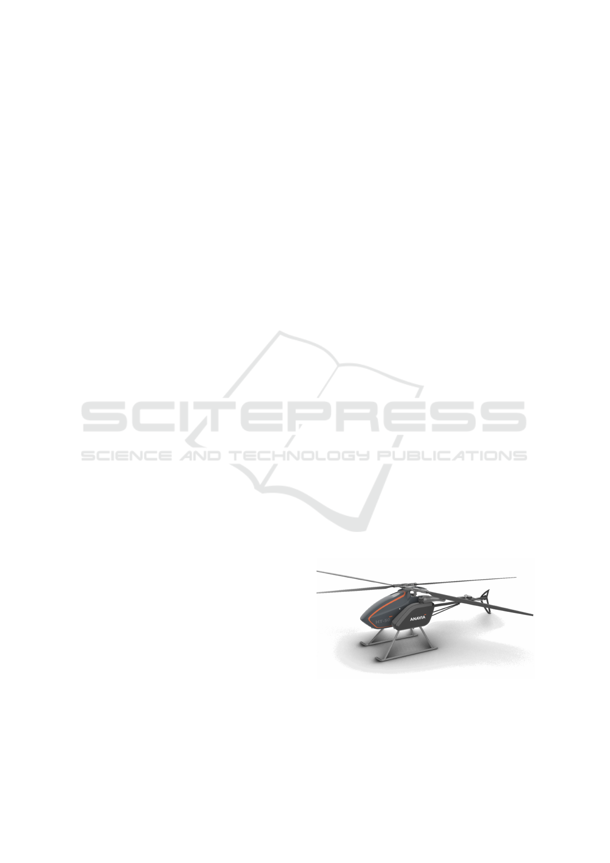
A VTOL system, a helicopter from ANAVIA, was
used as a carrier system for the sensor system.
ANAVIA’s HT-50 helicopter (ANAVIA, 2025b) fea-
tures a carbon fiber composite airframe and dual inter-
meshing Flettner rotors, emulating the full-scale flight
dynamics of the larger HT-100 system (ANAVIA,
2025a). Its maximum take-off weight (MTOW) is
50 kg with a payload capacity of 20 kg. Power is pro-
vided by a 7 kW shaft-driven microturbine coupled to
a high-performance gear. This type of drive is a ma-
jor difference from all the other approaches and pro-
totypes presented in1.2.
Fuel is stored in a 17 L tank. The helicopter con-
sumes approximately 10 L/h under cruise conditions.
HT-50 achieves a maximum flight time of 90 min and
has a top speed of 100 km/h. The system will be
able to fly a pre-planned mission fully autonomously.
However, the final version of the autopilot was not
yet installed during the tests, so all flights were flown
manually for our data collection.
Figure 3: HT-50 from ANAVIA was developed as a training
platform for the larger HT-100. It has a payload of 20 kg, a
flight time of 90 min and a maximum speed of 100 km/h.
Sky Savers: Leveraging Drone Technology for Victim Localization in Avalanche Rescue via Transceiver Signal Analysis
471
1.3.2 Hardware Setup Sensor System
Our system consists of an MAMMUT Pulse Barryvox
avalanche transceiver, a Raspberry Pi, a GPS-module,
an absolute Inertial Measurement Unit (IMU) and
a Power Supply. The design and arrangement of
the hardware components were chosen to achieve the
best possible sensitivity of the avalanche burial sig-
nal and to ensure precise localization through accu-
rate GPS data and efficient data processing. The
avalanche transceiver was mounted on the tailboom
of the VTOL system - a location with minimal possi-
bility of EMI. The Raspberry Pi serves as the central
processing unit (CPU) of the system. The CPU is re-
sponsible for managing the Universal Asynchronous
Receiver/Transmitter (UART) connection with the
avalanche transceiver, which allows real-time data
transfer from the transceiver to the central processing
unit.
The data received from the avalanche transceiver
include the direction and distance of the target, which
are used in the subsequent localization algorithms.
This data is then merged with the current GPS loca-
tion and heading information provided by the VTOL-
system. In this state of research, all computationally
expensive tasks, such as source localization or visu-
alization, are performed offline on a laptop after the
flight. The GPS data are then fused with the distance
and direction data from the avalanche transceiver to
locate the buried avalanche transceiver. As the current
aircraft did not yet have a fully functional autopilot
with real-time kinematics (RTK) on board, a HILTI
PLT-400 (Hilti, 2025) total station was used to track
the target on the ground. The corner points of the
search area were obtained with cm-accurate position
data.
1.4 Target Localization Approach
The magnetic field is generated by a static magnetic
dipole based on the analytical formulation shown in 1.
A magnetic dipole can be described by its dipole mo-
ment m. In our case, the dipole moment describes the
strength of the dipole and depends on the properties
of the coil.
B(r) = ∇ × A =
µ
0
4π
3r(m · r)
r
5
−
m
r
3
(1)
where B(r) is the magnetic field generated by the
transceiver at distance r, m = (m
x
, m
y
, m
z
)
T
is the
magnetic moment vector of the dipole that is given by
the specifications of the avalanche transceivers coils.
The constant µ
0
is the vacuum permeability. In the
current state of research, we do not have available B
field data from the avalanche transceiver, but only a
distance r and a direction value processed internally.
The use of the B field data would allow us to solve
the inverse problem via constrained optimization for
a more accurate localization.
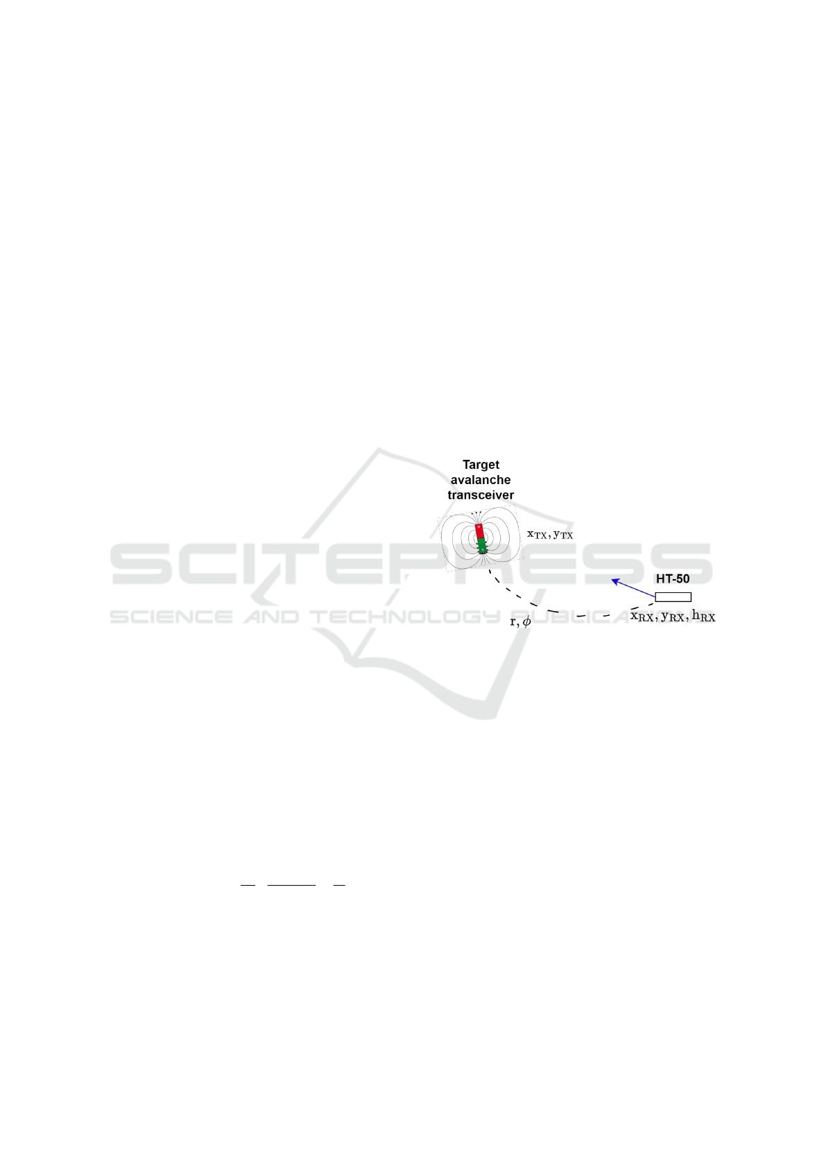
We employ a two-stage Extended Kalman Filter
(EKF) approach to estimate the (assumed stationary)
target coordinates (x
TX
, y
TX
). The first EKF (Smooth-
ing Filter) combines the raw directions ϕ and dis-
tance r measurements from the avalanche transceiver
with GPS position and heading (x
RX
, y
RX
, h
RX
) of the
drone for noise reduction. The second EKF (Track-
ing Filter) uses the smoothed measurements to update
the target estimate using the non-linear measurement
model, shown in 2. In Figure 4 we can find the high-
level schematic of the setup.
(
x
RX
+ r cos ϕ = x
TX
,
y
RX
+ r sin ϕ = y
TX
,
(2)
Figure 4: We have used one transceiver device in send
mode, as a target. A second system is used in search mode
on the VTOL-system to collect data and used for localiza-
tion.
1.4.1 Smoothing EKF
To robustly fuse coarse avalanche transceiver data
with precise GPS position and heading, we imple-
mented a simple EKF that smoothed outliers in direc-
tion and distance before propagating a second filter to
estimate the absolute location of the target.
State and Process Model
We define the state vector at time k as:
x
k
=
ϕ
k
r
k
, (3)
where ϕ
k
is the estimated direction to the buried
transceiver in degrees, and r
k
is the estimated distance
to the target in decimeters. The covariance P
k
∈ R
2×2
encodes the uncertainty.
ICINCO 2025 - 22nd International Conference on Informatics in Control, Automation and Robotics
472

Upon receiving new GPS data, indicating a dis-
placement of (∆x, ∆y) in meters from successive lat-
itude and longitude readings, we predict the next
state. The prediction model, which accounts for the
searcher’s movement, is given by:
ˆ
ϕ
k
= ϕ
k−1
+ α∆θ, (4)
ˆr
k
= max
r
k−1
− β∥[∆x, ∆y]∥, r
min
, (5)
where:
• ∆θ ∈ [−180
◦
, 180
◦
] is the angular difference be-
tween the GPS-derived motion heading and the
previously estimated direction of the transceiver
ϕ
k−1
.
• α and β are adaptive gain factors that reflect how
strongly the searcher’s motion is expected to in-
fluence the transceiver estimates. These gains
are dynamically adjusted on the basis of observed
movement.
• r
min
> 0 is a minimum distance threshold, pre-
venting non-physical negative ranges.
The predicted state covariance matrix
ˆ
P
k
is
evolved by adding the process noise covariance ma-
trix Q
k
:
ˆ
P
k
= P
k−1
+ Q
k−1
. (6)
The noise of the process Q
k
is dynamically tuned
to allow moderate drift in the estimated direction and
distance, its magnitude being adjusted based on the
speed of the searcher’s movement.
Measurement Update
When a new transceiver measurement (ϕ
meas
k
, r
meas
k
)
becomes available, we use a measurement matrix H =
I, as the measurements directly correspond to the state
variables. The residuals (innovations) are formed by
comparing the measurement with the predicted state,
with a proper angle wrapping in [−180
◦
, 180
◦
] for the
direction:
y
ϕ
= ((ϕ
meas
k
−
ˆ
ϕ
k
+ π) mod 2π) − π, (7)
y
r
= r
meas
k
− ˆr
k
. (8)
The measurement noise covariance matrix R
k
is
adaptively adjusted based on two primary factors:
• Range-dependent direction noise: A larger mea-
sured distance r
meas
k
implies higher directional un-
certainty, leading to an increased variance for
ϕ
meas
k
.
• Low-motion penalty: If the searcher’s movement
between updates is minimal (≪ 1 m), both direc-
tional and distance variances in R
k
are scaled up
to counteract potential spurious swings or static
measurement inaccuracies.
The Kalman gain K
k
and the subsequent state and
covariance updates are calculated as follows:
S
k
= H
ˆ
P
k
H
T
+ R
k
, (9)
K
k
=
ˆ
P
k
H
T
S
−1
k
, (10)
x
k
=
ˆ
ϕ
k
ˆr
k
+ K
k
y
ϕ
y
r
, (11)
P
k
= (I − K
k
H)
ˆ
P
k
(I − K
k
H)
T
+ K
k
R
k
K
T
k
. (12)
1.4.2 Tracking EKF
We employ another Extended Kalman Filter (EKF)
to estimate the fixed avalanche transceiver’s abso-
lute position (x
TX
, y
TX
) in a local Cartesian frame.
This filter takes advantage of the smoothed direction
and distance measurements provided by the avalanche
transceiver.
State and Process Model
The state vector at time k is defined as the target’s
estimated position:
x
k
=
x
TX,k
y
TX,k
, (13)
with its associated covariance matrix P
k
=
Cov(x
k
). Assuming the target remains stationary, the
prediction step simply propagates the state estimate
without change.
ˆ
x
k
= x
k−1
. (14)
However, the predicted state covariance evolves
by adding a small noise covariance matrix in the pro-
cess Q
k
:
ˆ
P
k
= P
k−1
+ Q
k
. (15)
The magnitude of Q
k
is adaptively reduced as
the search progresses through its phases (coarse, fine,
pinpoint), reflecting an increasing confidence in the
target’s immobility.
Non-linear Measurement Model
At each time step k, the searcher, located at
(x
RX
, y
RX
) in the same local cartesian frame, obtains
smoothed distance r
k
and direction ϕ
k
measurements
Sky Savers: Leveraging Drone Technology for Victim Localization in Avalanche Rescue via Transceiver Signal Analysis
473

from the avalanche transceiver. The non-linear mea-
surement function h : R
2
→ R
2
relates the target’s true
position (x
TX
, y
TX
) to these expected measurements:
r
k
=
q
(x
TX
− x
RX
)
2
+ (y
TX
− y
RX
)
2
, (16)
ϕ
k
= atan2(y
TX
− y
RX
, x
TX
− x
RX
). (17)
Thus, the measurement vector is z
k
= [ r
k
, ϕ
k
]
⊤
.
Jacobian Linearization
To incorporate these non-linear measurements into
the EKF framework, the measurement function h is
linearized about the predicted state
ˆ
x
k
. This yields the
measurement Jacobian matrix H
k
:
H
k
=
∂h
∂x
ˆ
x
k
=
x
TX
−x
RX
ˆr
k
y
TX
−y
RX
ˆr
k
−
y
TX
−y
RX
ˆr
2
k
x
TX
−x
RX
ˆr
2
k
, (18)
where ˆr
k
is the predicted smoothed distance cal-
culated using the predicted state
ˆ
x
k
and the searcher’s
position (x
RX
, y
RX
). To avoid singularities when the
searcher is very close to the estimated target position,
for very small ˆr
k
(specifically, ˆr
k
< 0.01 m), we sub-
stitute H
k
≈ I.
Measurement Noise Adaptation
The measurement noise covariance matrix R
k
is de-
fined as:
R
k
=
σ
2
r
0
0 σ
2
ϕ
, (19)
where:
• σ
r
is the standard deviation of the distance mea-
surement. Scales with the measured range r
k
(e.g.
σ
d
≈ 0.1 r
k
in phase 1, with a minimum of 1 me-
ter) and is significantly reduced in later search
phases (fine, pinpoint).
• σ
ϕ
is the standard deviation of the direction mea-
surement. It is also distance-dependent (inversely
proportional to range) and is further inflated if the
searcher is receding from the target. The vari-
ances for both distance and direction are dynam-
ically adjusted based on the current search phase,
with higher confidence assigned to measurements
received during later phases.
Update Equations
The innovation vector (residual) y
k
is formed by com-
paring the actual measurement z
k
with the predicted
measurement h(
ˆ
x
k
), ensuring proper angular wrap-
ping for the direction component:
y
k
=
r
k
− ˆr
k
ϕ
k
−
ˆ
ϕ
k
+ π
mod 2π− π
. (20)
Here, ˆr
k
and
ˆ
ϕ
k
are the predicted distance and di-
rection based on
ˆ
x
k
.
The subsequent EKF update equations are ap-
plied:
S
k
= H
k
ˆ
P
k
H
⊤
k
+ R
k
, (21)
K
k
=
ˆ
P
k
H
⊤
k
S
−1
k
, (22)
x
k
=
ˆ
x
k
+ K
k
y
k
, (23)
P
k
= (I − K
k
H
k
)
ˆ
P
k
(I − K
k
H
k
)
T
+ K
k
R
k
K
T
k
. (24)
The Kalman gain K
k
is further modulated based
on the search phase and whether the searcher is ap-
proaching or receding from the target.
2 RESULTS
The performance of the proposed VTOL-based local-
ization approach was evaluated in an open field test
site of about 50m × 50m. We adopted a horizon-
tal sweep search pattern as described in (Blankenship
et al., 2022), varying the spacing between the lines,
the flight height and the flight speed of the helicopter.
In total, ten flights were executed, not all on the same
day and on the same location.
The helicopter was manually controlled by an ex-
perienced pilot, who was informed of current altitude
above ground (AGL) and current flight speed at reg-
ular intervals from another operator reading out flight
information from a ground station terminal.
2.1 Ground Tests
Prior to flight tests, we performed stationary ground
tests to assess the impact of sensor placement on the
sensitivity of localization during turbine running. By
mounting the avalanche transceiver on the VTOL tail-
boom, thus increasing distance from the gas turbine,
fuel pump and onboard electronics, we improved the
effective detection range from approximately 10 m to
up to 30 m. This threefold gain demonstrates that
simple mechanical separation from high-EMI compo-
nents can markedly enhance transceiver signal qual-
ity.
2.2 Sensitivity Experiments
As an initial test, the sensitivity of the sensor system
was analyzed during flying. For this purpose, the tar-
get was placed with an offset of 3 m in the x and y
directions to the helicopter. The VTOL system then
flew vertically upward during data recording. The re-
sults in Figure 5 showed that it is possible to track the
ICINCO 2025 - 22nd International Conference on Informatics in Control, Automation and Robotics
474
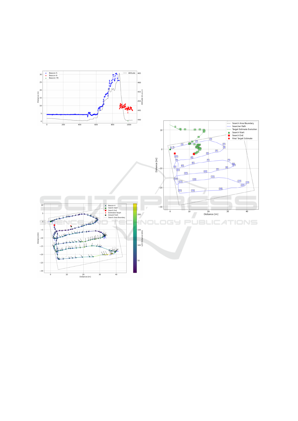
target up to a distance of 30 m. Compared to the tests
by (Ricciardi, 2017), we achieved a range that was
three to four times higher.
Figure 5: The collected distance data from the transceiver
to the target is shown in blue. The dashed black line shows
the height of the VTOL system in meters above sea level
(m.a.s.l.). After the system had reached an altitude of 30
m, the helicopter turned off and then began tracking another
target (shown in red and green), but this is not relevant to the
test result.
2.3 Test-Flight Experiments
Following ground validation and sensitivity analysis,
we conducted in total ten flights to investigate the lim-
its of the system.
Figure 6: Results of a test-flight: raw transceiver direction
(dotted gray arrows) and distance (colored markers), current
transceiver ID (markers shape), smoothed direction and po-
sition (black arrows), and final estimated target location (red
cross) and ground truth (green star). The dotted line around
the flight path marks the search area boundary.
For the test flight in Figure 6 we chose a spacing
between the lines of 5 m. The pilot flew at a height
of 3 m above ground and a speed of 2 m/ s. Both,
altitude and airspeed, varied slightly due to the lack
of an autopilot. The green and red squares show the
start and stop points of the helicopter.
2.4 Flight-Path and Target Localization
The direction readings (dotted gray arrows) and dis-
tance measurements (colored markers) in Figure 6are
the noisy raw data collected from the avalanche
transceiver. After smoothing the direction and dis-
tance, the estimated target location (red cross) con-
verges near the true target location (green star). The
Euclidean distance between the ground truth and the
estimation was 0.63,m in this experiment. Using RTK
positioning of the drone could further increase the lo-
calization accuracy.
Figure 7: Evolution of the Tracking EKF’s estimated target
position (in green) in the horizontal plane over time. The
blue lines show the flight path. The numbers indicates the
current index of the datapoint.
Figure 7 depicts the Tracking EKF’s state estimate
of the target’s (x
TX
, y
TX
) coordinates. The plot shows
how the position of the target estimated by the EKF
converges in the proximity of the ground truth posi-
tion.
2.5 Discussion
The purpose of the paper was to demonstrate the func-
tionality of a helicopter-based localization system.
The current state-of-the-art is and remains companion
rescue.
The added value of the system comes into play
in dangerous conditions or in very large avalanche
cones, where it is difficult to move on foot. Field tests
must be carried out to compare such scenarios, but
this has not yet been done and will only be the case
when the system is further developed.
Sky Savers: Leveraging Drone Technology for Victim Localization in Avalanche Rescue via Transceiver Signal Analysis
475

3 CONCLUSION
In this work, we have presented a novel VTOL-based
avalanche victim localization system that overcomes
key limitations of existing brushless motor-driven
platforms presented in section 1.2. By replacing noisy
DC motors with a turbine, we effectively avoided EMI
issues in avalanche transceiver signals and demon-
strated submeter localization accuracy under realistic
field conditions. The use of a turbine-powered VTOL
system allows operations in cold weather conditions
and rugged alpine terrain, greatly extending the prac-
tical utility of search and rescue missions.
In the future, we plan to integrate raw B field
vector measurements directly from the avalanche
transceiver coil to refine position estimates and im-
prove the overall localization precision. We will also
explore inverse optimization methods to enable si-
multaneous tracking of multiple buried subjects. To
realize a fully end-to-end rescue solution, future work
will focus on:
• Developing (semi-) autonomous flight trajectories
for rapid deployment to the accident site,
• Incorporating on-board camera and LiDAR sen-
sors for real-time estimation of the avalanche cone
geometry and safe landing zones,
• Designing a reliable target-marking mechanism
such as visual markers to guide ground teams to
located victims.
These advances will be critical to the delivery
of a complete and life-saving system capable of au-
tonomous search, pinpoint location, and target mark-
ing in harsh mountain environments.
ACKNOWLEDGEMENTS
The authors appreciate the support provided by GPV
AG and MAMMUT AG. Their provision of avalanche
transceivers, as well as the corresponding interfaces
and communication protocols, was essential for the
development and execution of this research. The au-
thors also thank HILTI AG for providing the PLT
400 total station and support with data extraction.
The project was funded by Innosuisse’s Innovation
Booster Robotics program.
REFERENCES
Alcedo (2010). Alcedo: A drone-based avalanche rescue
prototype. Unpublished student project report, ETH
Zurich.
ANAVIA (2025a). Ht-100.
ANAVIA (2025b). Ht-50.
Association, A. A. (2025). Avalanche fatalities statistics.
https://avalanches.org/fatalities/fatalities-statistics/.
[Accessed: April 23, 2025].
ATLASUAS (2025). Atlasavalanche pro system overview.
Product brochure; employs a flexible transceiver
mounting to reduce EMI.
Ayuso, N., Cuch
´
ı, J., Lera, F., and Villarroel, J. (2015). A
deep insight into avalanche transceivers for optimiz-
ing rescue. Cold Regions Science and Technology,
111:80–94.
Azzollini, I. A., Mimmo, N., Gentilini, L., and Marconi, L.
(2020). Uav-based search and rescue in avalanches
using arva: An extremum seeking approach. In IFAC-
PapersOnLine, volume 53, pages 1627–1632.
Blankenship, R., Bluman, J., and Steckenrider, J. (2022).
An investigation of search algorithms for aerial recon-
naissance of an area target. In Proceedings of the An-
nual General Donald R. Keith Memorial Conference,
pages 72–77, West Point, New York, USA. IEWorld-
Conference.org. A Regional Conference of the Soci-
ety for Industrial and Systems Engineering.
Bluebird (2021). Powderbee drone system. Dissolved on
August 10, 2021.
Brugger, H., Etter, H. J., Zweifel, B., Mair, P., Hohlrieder,
M., Ellerton, J., Elsensohn, F., Boyd, J., Sumann, G.,
and Falk, M. (2007). The impact of avalanche rescue
devices on survival. Resuscitation, 75(3):476–483.
DJI (2025). Matrice 200 series.
ETSI (2017). Avalanche beacons operating at 457 khz;
transmitter–receiver systems; part 1: Harmonised
standard for access to radio spectrum.
Falk, M., Brugger, H., and Adler-Kastner, L. (1994).
Avalanche survival chances. Nature, 368(6466):21–
21.
Hilti (2025). Plt 400-4 – digitale absteckger
¨
ate. https:
//www.hilti.ch/content/hilti/CH/de/home.html. Laser
measuring tool.
Janovec, M., Kandera, B., and
ˇ
Sajbanov
´
a, K. (2022). Using
unmanned aerial vehicles during the search of people
buried in an avalanche. Transportation Research Pro-
cedia, 65:350–360.
Mammut (2024a). Barryvox pulse. Older generation sum-
mit beacon, discontinued 2017.
Mammut (2024b). Barryvox s. Avalanche transceiver with
3-antenna digital/analog, 70 m search strip width.
Nivitec (2020). Nivitec drone assisted avalanche rescue sys-
tem. project inactive since 2020.
Ricciardi, F. (2017). Automatic Search of Missing People in
Avalanches. Master’s thesis, Alma Mater Studiorum
– University of Bologna, Bologna, Italy.
Silvagni, M., Tonoli, A., Zenerino, E., and Chiaberge, M.
(2017). Multipurpose uav for search and rescue oper-
ations in mountain avalanche events. Geomatics, Nat-
ural Hazards and Risk, 8(1):18–33.
Toson, F., De Giudici, F., Piva, A., and Menegatti, E.
(2021). Averla: Autonomous drone for avalanche res-
cue. In Proceedings of the XXVI AIDAA Congress.
ICINCO 2025 - 22nd International Conference on Informatics in Control, Automation and Robotics
476
