
Performance Analysis and Improvement of Double Circuit EHV AC
Transmission Lines by Increasing Surge Impedance Loading Level
Jitendra G. Jamnani
a
and Varun Patel
School of Energy Technology, Pandit Deendayal Energy University, Gandhinagar, Gujarat, India
Keywords: SIL (Surge Impedance Loading), Bundle Spacing, EHV (Extra High Voltage) AC Transmission, Expanded
Hexa, Delta Configuration, Hexagon Configuration.
Abstract: The demand of Electrical Energy is continuously increasing due to the growth of society and industrialization
and to fulfil this requirement, increase in power generation and its transmission at high efficiency is required.
Extra high voltages are necessary to transfer large amount of power over linger distances as the power transfer
limit is proportional to the square of rated voltage. Generally the power generating stations are far away from
the distribution network and to connect the power surplus region to power deficit region we need long EHV
AC double circuit transmission lines to carry large amount of power. But the long EHV AC transmission lines
are limited by their SIL (Surge Impedance Loading) limit which is much below the thermal limit of conductor
due to large inductive reactance of the line. SIL depends on various factors and geometrical arrangement of
double circuit transmission lines i.e. bundle spacing, size of conductor, number of sub-conductors per phase,
etc. This paper presents various methodologies to improve SIL level of EHV AC lines and also its effect on
corona loss. MATLAB is used as platform for development of GUI based software to calculate and analyze
the various parameters related to SIL and corona loss. The various double circuit configurations used for EHV
AC transmission lines and its comparison is also presented.
1 INTRODUCTION
Extra high voltages are necessary for transfer of large
amount power over longer distances. To transfer
more power, higher transmission voltage is
necessary. Power transfer limit is proportional to the
square of rated voltage. For the same power transfer,
the line losses reduce with higher rated voltage due to
reduction in current. With higher Transmission
Voltage, conductor size requirement is reduced.
Therefore conductor cost will reduce. To transfer
large amount of power from power surplus region or
state to power deficit states or region requires long
EHV AC transmission lines. However long EHV AC
transmission lines are limited by SIL (Surge
Impedance Loading) / Stability limits due to large
inductance of the lines(Nayak, Sehgal, et al. , 2022),
(Daconti and Daniel, 2023).
a
https://orcid.org/0000-0001-6238-1222
2 SURGE IMPEDANCE
LOADING (SIL) AND CORONA
LOSS
SIL is the MW loading of the line where natural
reactive power balance occurs i.e. reactive power
produced by a line is equal to reactive power
consumed by a line. If we load the line above SIL the
line would consume reactive power and limits the
power transfer capacity to maintain stability of the
system.
The surge impedance loading concept is suitable
for EHV AC lines to decide the MW loading and
corresponding voltage variation along the line length.
To increase SIL level, line inductance is to be reduced
and /or capacitance is to be increased. (Hao and Xu,
2022), (Kishore, Singal, et al. , 2021), (Siva, Rani, et
al. , 2020)
Corona is formed due to ionisation of air
surrounding the conductors. The formation of corona
is always accompanied by Energy loss which is
Jamnani, J. G. and Patel, V.
Performance Analysis and Improvement of Double Circuit EHV AC Transmission Lines by Increasing Surge Impedance Loading Level.
DOI: 10.5220/0013734200004664
Paper published under CC license (CC BY-NC-ND 4.0)
In Proceedings of the 3rd International Conference on Futuristic Technology (INCOFT 2025) - Volume 3, pages 871-876
ISBN: 978-989-758-763-4
Proceedings Copyright © 2025 by SCITEPRESS – Science and Technology Publications, Lda.
871
dissipated in the form of light, heat, sound and
chemical action. When corona occurs, it produces
loss of power. For calculation of SIL,
SIL =
, where Zs is surge impedance and is
given by
Zs =
and inductance L is given by
L = Ls–Lm
Ls = self-inductance of line=2* 10
𝑙𝑛
H/m
Lm = mutual inductance of the line=2* 10
𝑙𝑛
H/m
Where GMD is geometric mean distance between
conductors and GMR is the geometric mean radius of
conductor.
For calculation of corona, the foul weather
condition is selected which is worst. So the formula
used to calculate corona is Project EHV, USA by
Anderson, Baretsky and McCarthy Formula.
Pc = Pfw + 0.3606 k. V. 𝑟
.ln (1+10ρ).
∑
𝐸
Where,
Pc = Foul weather corona loss
Pfw = total fair weather corona loss = 1 to 5
kw/km for 500 kV and 3 to 20kw/km for 700kV,
for calculation of 400kV line Pfw is taken as 5
kw/km.
K = 7.04 * 10
for 400kV (based on Rheinau
results)
V = conductor voltage in kV, l-l r.m.s
E = surface voltage gradient on the underside of
the conductor, kV/cm, peak
ρ = rain rate in mm/hr, taken as 5mm/hr
r = radius of conductor in cm
N = no. of sub conductors in bundle of each phase
Voltage gradient is calculated using standard
mangoldt’s formula.
3 METHODOLOGIES TO
INCREASE SURGE
IMPEDANCE LOADING LEVEL
CONSIDERING CORONA LOSS
For long transmission lines the power transfer
capacity is limited by its SIL level only which is much
below its thermal capacity due to large inductance.
Also Decrease in line inductance and surge
impedance shall increase the SIL and transmission
capacity.
The surge impedance loading (SIL) depends on
many factors such as (a) phase spacing (b) Bundle
spacing (c) size of conductor (d) number of sub-
conductors per phase and (e) conductor
configurations. In this research paper, for a particular
data of 400kV double circuit transmission line
configurations, the effect of Bundle spacing, size of
conductor, Number of sub-conductors per phase,
Horizontal and vertical spacing on SIL level and
corona loss is presented and hence to improve the
power transmission capacity.
MATLAB is used as platform for development of
GUI based software to calculate and analyze the
various parameters related to SIL and corona loss.
The various double circuit configurations used for
EHV AC transmission lines and its comparison is also
presented.
The above methods have been analyzed and
discussed for 400kV Double circuit transmission line
and there result tables and graphs showing its effect
on SIL and Corona loss has been presented. The
parameters used to obtain the results have been shown
in the graph itself
. (Sakhavati, Yaltagiani, et al. , 2020),
(Begamudre, 2020), (Saadat, 2020), (Dritsas, Alexiou, et al.
, 2022), (Gupta, Saha, et al. , 2021)
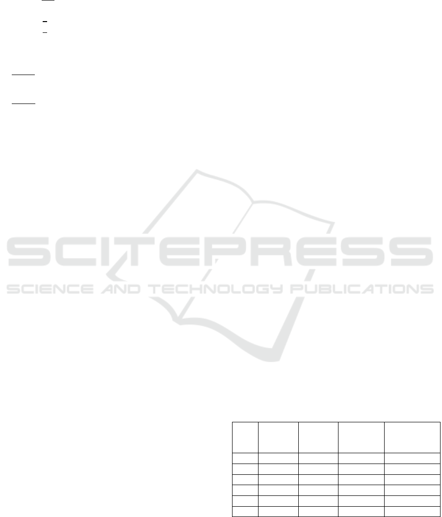
3.1 Bundle Spacing (B)
Bundle spacing is the spacing between sub-
conductors, as the B increases Bundle radius R
increases and GMReq of bundled conductor
increases, which leads to reduction in self-inductance
of the line and we can have reduction in line
inductance and increase in SIL level as the B
increases. However the corona loss would slightly
increase with increase in bundle spacing but
comparative to that there is large increment in SIL
level is obtained. The Table 1 and Figure 1 show the
effect of change in bundle spacing on SIL and corona
loss.
Table 1: Bundle Spacing (B) in cm v/s SIL and Corona
B
(cm
)
L(mH/k
m)
C(nF/k
m)
SIL
(MW)
Pc(kw/3phas
e km)
35 0.389 29.05 1382.65 11.55
40 0.379 29.84 1419.48 11.76
45 0.37 30.56 1453.63 12.04
50 0.362 31.24 1485.0 12.37
55 0.355 31.88 1515.77 13.13
60 0.349 32.48 1544.39 13.55
INCOFT 2025 - International Conference on Futuristic Technology
872
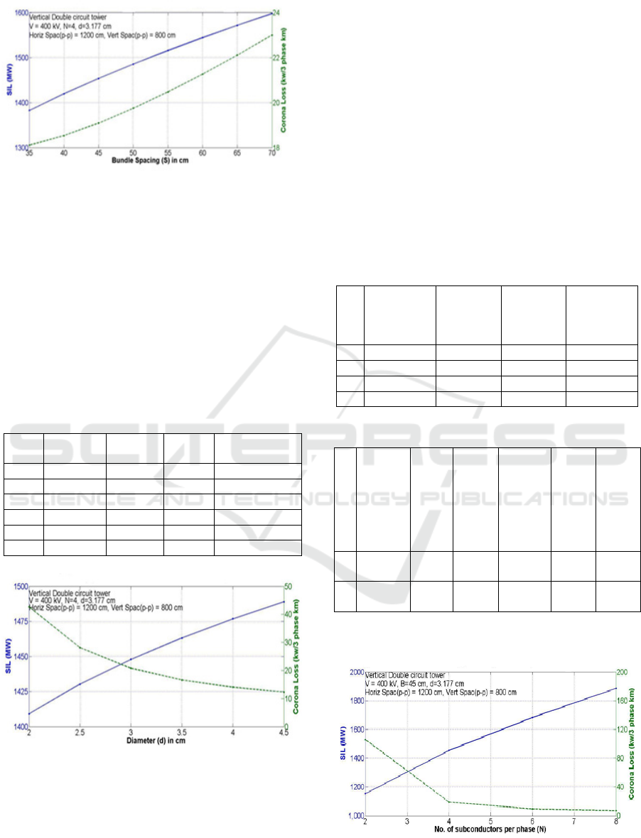
Figure 1: Bundle Spacing (B) v/s SIL and Corona
3.2 Size of Conductor (d)
The diameter of the conductor is the size of conductor,
with the increase in diameter of conductor the GMReq of
the conductor increases and self-inductance of the line
reduces, hence there is reduction in inductance of the line
and there is increase in SIL level. There would also be more
reduction in the corona loss is obtained with increase in
diameter of conductor. The Table 2 and Figure 2 show the
effect of change in diameter of conductor on SIL and corona
loss.
Table 2: Diameter of Conductor (d) in cm v/s SIL and
Corona
d
(
cm
)
L
(
mH/km
)
C
(
nF/km
)
SIL
(
MW
)
Pc(kw/3phase
km
)
2 0.381 29.62 1409.2 11.55
2.5 0.376 30.06 1430.2 11.76
3 0.371 30.44 1447.9 12.04
3.5 0.367 30.76 1463.2 12.37
4 0.364 31.05 1476.8 13.13
4.5 0.361 31.31 1488.9 13.55
Figure 2: Diameter of conductor (d) v/s SIL and Corona
3.2.1 No. of Sub-conductors per phase
(Bundle) (N)
The No. of sub-conductors in a bundle increases there
would be rise in the GMReq of the conductor which
would reduce self-inductance of the line, and
reduction in inductance of the line, therefore there
will be increment in SIL level. There is a large
increment in SIL level is obtained and current
carrying capacity also increases. Also corona loss
would reduce drastically with increase in N. However
increase in N the loading on existing transmission
tower increases so to reduce the weight we can shift
from twin ASCR moose conductor to quad ACSR
zebra conductor having reduced diameter and weight,
but still the overall weight on tower increases, so it is
possible only when from the tower is designed to
carry increases weight so that we can fulfil the
requirement of future increase in power demand. The
following Table 3,4 and Figure 3 shows the effect of
change in No. of sub conductors per phase on SIL.
Table 3: N v/s SIL and Corona
N
L
(mH/km)
C
(nF/km)
SIL
(MW)
Pc
(kw/
3phase
km)
2 0.469 24.38 1153.9 55.49
4 0.37 30.56 1453.63 12.04
6 0.319 35.32 1683.33 7.16
8 0.285 39.52 1885.39 5.95
Table 4: N v/s SIL and Corona (including weight and cost)
N
ACSR
Condu
ctor
diamet
er (cm)
Wei
ght
(kg/
km)
Appr
ox.
Cost
of
cond.
(Rs./
m)
SIL
(MW)
Diffe
rence
in
MW
Pc
(kw/
3phas
e km)
2
Moose
3.177
2004 300 1153.9 0 55.49
4
Zebra
2.862
1621 260 1443.4 289.5 13.71
Figure 3: No. of Sub-conductors per phase (N) v/s SIL and
Corona
Performance Analysis and Improvement of Double Circuit EHV AC Transmission Lines by Increasing Surge Impedance Loading Level
873
3.2.2 Horizontal Spacing
The phase to phase spacing is a factor of GMD
(Geometric Mean Distance), i.e. if the spacing
between conductors is reduced GMD will decrease
and there will be increase in mutual inductance of the
line which leads to reduction in line inductance and
increase in SIL level. However there is limit on the
spacing between conductors due to sag of the
conductors. This is due to the fact that more the sag
more is the swing of the conductor and there are
chances of p-p faults, but if we use V string insulators
or conductor is replaced with HTLS (high
temperature low sag conductors) eg. ACSS
(Aluminium Conductor Steel Supported) either both
the swinging of conductor is reduced and the spacing
of conductors can be reduced. The Table 5 and Figure
4 show the effect of change in spacing between the
bundles on SIL.
Table 5: P-P Spacing v/s SIL and Corona
P-P
spacin
g (m)
L
(mH/km)
C
(nF/km)
SIL
(MW)
Pc
(kw/3p
hase
km)
10 0.366 30.90 1469.80 12.63
11 0.368 30.72 1461.32 12.31
12 0.37 30.56 1453.63 12.04
13 0.372 30.41 1446.69 11.83
14 0.374 30.28 1440.43 11.66
15 0.375 30.16 1434.81 11.51
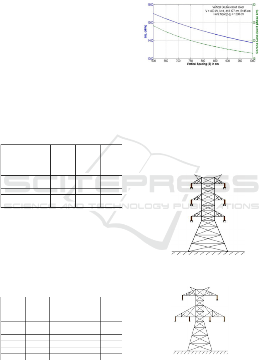
3.2.3 Vertical Spacing
The reduction in vertical spacing reduces GMD
which leads to increases in the SIL level. But we
cannot reduce this spacing much because we have to
see the spacing of conductor from tower as well as the
below crossarm. However we can reduce this spacing
till the voltage gradient and corona loss is within
limit. The Table 6 and Figure 5 show the effect of
change in vertical spacing between the phases on SIL.
Table 6: Vertical Spacing v/s SIL and Corona
Vertical
spacing
(m)
L(mH/k
m)
C
(nF/km
)
SIL
(MW)
Pc
(kw/
3phase
km
)
7 0.36 31.46 1496.14 13.06
7.5 0.365 30.99 1473.83 12.51
8 0.37 30.56 1453.63 12.04
8.5 0.375 30.17 1435.19 11.65
9 0.379 29.81 1418.23 11.30
9.5 0.384 29.48 1402.53 11.01
Figure 5: Vertical Spacing v/s SIL and Corona
4 DOUBLE CIRCUIT
CONFIGURATIONS
The arrangement of conductors also affects the SIL.
The transmission line inductance can be reduced by
proper geometrical configuration of conductors. For
a 400kV Double circuit tower the configurations are
as shown in figure 6, 7, 8 and 9.
4.1 Vertical tower
Figure 6: Vertical tower
4.2 Delta tower
Figure 7: Delta tower
INCOFT 2025 - International Conference on Futuristic Technology
874
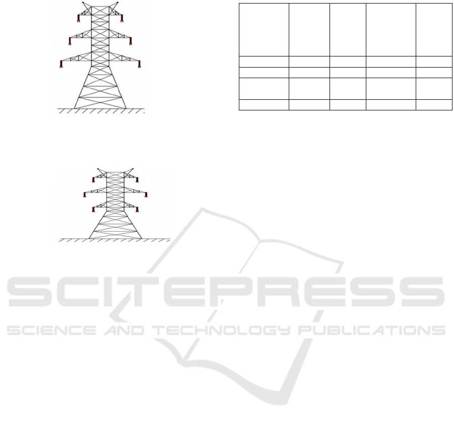
4.3 Inverted V tower
Figure 8: Inverted V tower
4.4 Hexagon tower
Figure 9: Hexagon tower
5 COMPARISON OF DOUBLE
CIRUCIT CONFIGURATIONS
Comparing Horizontal, Delta and L configuration
Towers in terms of SIL level for a specific given data
V = 400kV, N = 4, B = 45 cm, d = 3.177 cm
(moose conductor)
•
For vertical configuration S = 1200 cm (
horizontal p-p spacing), S = 800 cm
(Vertical p-p spacing)
•
For delta configuration Dhb = Dhy1 = 600
cm, Dhy = Dhr1 = 1400 cm, Dhr = Dhb1 =
1000 cm, Dvry = Dvbr = Dvy1b1 = Dvr1b1
= 692.82 cm, Dvyb = Dvr1y1 = 0 cm, Dry =
Dyb = Dbr = Dr1y1 = Dy1b1 = Db1r1 = 800
cm
•
For Inverted V Configuration Dhr = Dhb1 =
600cm, Dhb = Dhr1 = 800 cm, Dhy = Dhy1
= 700 cm, Dvry = Dvyb = Dvr1y1 = Dvy1b1
= 800 cm, Dvbr = Dvr1b1 = 1600 cm
• For Hexagon configuration Dhr = Dhb1 =
Dhb = Dhr1 = 600cm, Dhy = Dhy1 = 800
cm, Dvry = Dvyb = Dvr1y1 = Dvy1b1 = 800
cm, Dvbr = Dvr1b1 = 1600 cm
Where, Dhr = Horizontal distance of R phase
from centre of tower, Dvry = Vertical distance
between R and Y phase.
Table 7: Comparison of various Double circuit line
configurations
Double
Circuit
Configura
tions
L(mH/
km)
C(nF/
km)
Fair
corona
loss
(kw/3phas
e km)
SIL
(MW)
Vertical 0.37 30.56 0.65 1453.6
Delta 0.365 31.04 0.65 1476.2
Inverted
V
0.374 30.25 0.64 1439.0
Hexagon 0.369 30.63 0.64 1456.9
5.1 Advantages of using Delta
configuration and Hexagon
Configuration over Vertical
• There is an increase of approx. 23 MW in
SIL for delta compared to Vertical.
• The advantage of using Delta
configuration is reduction in no. of cross
arm requirement. Also height of the tower
can be reduced using Delta tower
compared to vertical.
• There is no need for transposition of lines
as the spacing between the lines is
symmetrical, hence the voltage drop
would be equal among the lines.
• There is an increase of approx. 3.3 MW in
SIL for Hexagon compared to Vertical.
6 CONCLUSIONS
The power transmission capacity of long EHV AC
lines is limited by SIL/Stability limits due to the
presence of large inductance of the line. So by
reducing the inductance and hence inductive
reactance and surge impedance, the power transfer
capacity can be enhanced. The decrease in inductance
and surge impedance would increase SIL level. The
Various techniques to increase SIL level close to
thermal limit can be done by
• Reduction in spacing between conductors (p-
p),
• Increase in bundle spacing
• Increase in diameter of conductor
• Increase in no. of sub-conductors per phase
The comparison for EHV AC 400 kV double
circuit tower configurations have been done. The
double circuit configurations considered for
comparisons are Vertical, Hexagon, Inverted V, and
delta tower configuration. The delta and Hexagon
Configuration shows increment in SIL compared to
Performance Analysis and Improvement of Double Circuit EHV AC Transmission Lines by Increasing Surge Impedance Loading Level
875

vertical tower, as well as it is possible to reduce height
of tower. Hence it is possible to enhance the power
transfer capability by above different techniques.
REFERENCES
R. N. Nayak, Y K Sehgal and Subir Sen, “EHV
Transmission line capacity Enhancement through
increase in Surge Impedance Loading Level, Published
in Power India Conference, (2006 IEEE).
Jose R. Daconti and Daniel c. Lawry “Increasing Power
Transfer Capability of Existing Transmission Line”,
Published in Transmission and Distribution Conference
and Exposition, (2003 IEEE).
Jin Hao and Wilsun Xu, “Extended Transmission line
Loadability Curve by including Voltage Stability
Constraint”, Published in Electric Power Conference,
(2008 IEEE Xplore).
Kishore T.S; Singal S.K., “Design Economics of EHV
Power lines ”, Advances in Electrical Engineering
(ICAEE), 2014 international IEEE conference
publication.
Gaddam Siva, Priyanka Rani, Anubhav Tiwari, Aditya
Gaddam, “Methods, Merits and Demerits of Improving
Power Transfer Capability based on Voltage and Surge
Impedance”, International Journal of Engineering
Research & Technology, Vol. 3 Issue 3, March 2014,
ISSN : 2278-0181.
Aydin Sakhavati, Mostafa Yaltagiani, Shirin Saleh Ahari,
Seyed Mahdi Mahaei,“765 kV Transmission line
Design (Electrical Section)” International Journal of
Electrical and Computer Engineering (IJECE) Vol.2,
No.5, October 2012, pp. 698~707 ISSN: 2088-8708
Rakosh Das Begamudre, Extra High Voltage Ac
Transmission Engineering, 3
rd
edition, New Delhi, New
Age International Publisher, (2006).
Hadi Saadat, Power System Analysis, McGraw Hill
Publisher (1999).
CEA yearly Report on Electricity Generation Review 2011-
2012.
Indian Standard IS 5613 (part 3) Code of Practice for
Design, Installation and Maintenance of 400kV
Overhead Power Lines.
Fajar Tri Wardana; Rudy Setiabudy, Study of Increasing
Surge Impedance Loading (SIL) and Voltage at
DEPOK Substation by Changing TASIK-DEPOK 500
kV Transmission Line's Configuration, at IEEE 2019
2nd International Conference on High Voltage
Engineering and Power Systems (ICHVEPS), October
01-04,2019, held at Denpasar, Indonesia.
Amir Lotfi; Mona Ghassemi, Smart Transmission
Expansion Planning Based on Unconventional High
Surge Impedance Loading Line Designs, at 2021 IEEE
Power & Energy Society Innovative Smart Grid
Technologies Conference (ISGT), February 16-18,
2021 held at Washington, DC, USA.
Jitendra Jamnani; Varun Patel, Surge Impedance Loading
level enhancement of 765 kV long EHV AC line
through bundle configurations, at IEEE 2016 Biennial
International Conference on Power and Energy
Systems: Towards Sustainable Energy (PESTSE),
January 21-23, 2016 held at Bengaluru, India.
Bhuban Dhamala; Mona Ghassemi, Transmission
Expansion Planning via Unconventional High Surge
Impedance Loading (HSIL) Lines, at 2023 North
American Power Symposium (NAPS), October 15-17,
2023 held at Asheville, NC, USA.
INCOFT 2025 - International Conference on Futuristic Technology
876
