
Curvature-Constrained Motion Planning and Control for Traffic Cone
Manipulation Robot
Rudolf Krecht
a
and
´
Aron Ballagi
b
Department of Automation and Mechatronics, Sz
´
echenyi Istv
´
an University, Egyetem square, Gy
˝
or, Hungary
Keywords:
Intralogisctics, Automatic Traffic Cone Manipulation, Curvature-Constrained Path Following, GNSS-RTK
Navigation.
Abstract:
This paper presents an integrated system for traffic cone manipulation using a heavy-duty mobile robot
equipped with GNSS-RTK localization, a custom remote supervision and mission control interface, and a
curvature-constrained motion controller. Designed for use in semi-structured outdoor environments, the robot
receives waypoint and speed commands via a tailored extension of Foxglove Studio, which enables intuitive
map-based interaction and real-time trajectory editing. Owning to its high payload capacity, the platform pri-
oritizes stability over maneuverability, thus, it cannot change orientation without longitudinal movement. To
address this, we propose a smooth, curvature-based controller that enforces a minimum turning radius while
following pose and heading goals. The system architecture is built on Robot Operating System 2 (ROS 2),
leveraging modular nodes for map visualization, path planning, motion execution, and action triggering. Our
experiments demonstrate the system’s ability to navigate complex waypoint paths and pause precisely at
mission-dictated locations, more specifically cone placement locations. Our results show that even under
turning constraints, the robot reliably executes full cone manipulation routines with high spatial accuracy and
operational safety. The system highlights the feasibility of pairing high-level operator interfaces with low-level
kinematic-aware planning for constrained robotic platforms.
1 INTRODUCTION
Autonomous transportation technologies are rapidly
reshaping the way people, goods, and infrastructure
interact in both urban and industrial environments.
Although much of the early focus in autonomy has
been directed towards large-scale vehicular automa-
tion, such as autonomous cars and trucks, recent ad-
vances have highlighted the critical importance of
smaller, task-specific systems that operate in con-
strained, semi-structured domains. Two key domains
in this emerging landscape are intralogistics and mi-
cromobility, both of which benefit significantly from
the deployment of compact, autonomous robotic sys-
tems.
Intralogistics refers to the automated management
of material flow within localized facilities such as
warehouses, ports, campuses, and construction sites.
These environments typically require frequent but
repetitive motion of small payloads, precise object
placement, and coordination with human workers or
a
https://orcid.org/0000-0002-8927-8783
b
https://orcid.org/0000-0002-5458-5249
static infrastructure. The ability to automate such
processes has direct implications on operational effi-
ciency, safety, and cost reduction. In this context, au-
tonomous mobile robots (AMRs) equipped with accu-
rate localization, adaptable planning, and simple ma-
nipulation capabilities have become increasingly rel-
evant (Pfrommer et al., 2024).
Parallel to this, the concept of micromobility has
emerged as a framework for understanding small-
scale robotic transportation—both for personal mo-
bility (e.g., scooters, delivery drones) and for au-
tonomous systems tasked with maintaining or re-
configuring urban environments. Examples include
robots that paint road markings, distribute tempo-
rary signage, or manage traffic cones in dynamic
zones such as smart test tracks and urban experiments.
These systems share the need for tight control in con-
strained areas, human-readable behavior, and smooth
integration into existing infrastructure.
Despite growing interest in these domains, rela-
tively little attention has been paid to robotic systems
that perform infrastructure manipulation tasks, such
as placing or removing traffic cones, in coordination
Krecht, R. and Ballagi, Á.
Curvature-Constrained Motion Planning and Control for Traffic Cone Manipulation Robot.
DOI: 10.5220/0013720700003982
Paper published under CC license (CC BY-NC-ND 4.0)
In Proceedings of the 22nd International Conference on Informatics in Control, Automation and Robotics (ICINCO 2025) - Volume 2, pages 317-324
ISBN: 978-989-758-770-2; ISSN: 2184-2809
Proceedings Copyright © 2025 by SCITEPRESS – Science and Technology Publications, Lda.
317

with mobile navigation. These tasks require the com-
bination of precise positioning, safe low-speed con-
trol, and intuitive human–robot interfaces for real-
time supervision. Moreover, the challenge is exac-
erbated when using large or heavy platforms that are
characterized by low maneuverability.
In this paper, we present a complete system for
cone manipulation using a GNSS-guided autonomous
robot, equipped with a curvature-aware controller and
a custom supervision and mission control interface
built on Foxglove Studio (Foxglove, 2024). The sys-
tem enables an operator to define traffic cone place-
ment locations on a live map, and based on the re-
quired traffic cone positions, the integrated motion
planner assigns speed profiles and behavioral seman-
tics, and finally, the controller executes the required
path. The robot tracks these trajectories using a cus-
tom controller that enforces a minimum turning ra-
dius, ensuring feasibility even under physical mo-
tion constraints. The result is a lightweight, adapt-
able solution for localized infrastructure manipula-
tion—applicable to intralogistics scenarios, micromo-
bility deployments, and emerging smart-city test en-
vironments. The setup presented in this paper was
developed and tested at the ZalaZONE Automotive
Proving Ground (ZalaZONE Research and Innova-
tion, 2023).
2 RELATED WORK
The integration of autonomous mobile robots
(AMRs) into intralogistics and micromobility sys-
tems has received significant attention in recent years,
driven by the need for efficient, flexible and safe trans-
portation solutions within structured environments.
AMRs have revolutionized intralogistics by
enabling decentralized problem solving and au-
tonomous navigation in dynamic environments (Fra-
gapane et al., 2021). These robots are increasingly
employed in manufacturing, warehousing, and hos-
pital settings to automate material handling tasks.
The shift from traditional automated guided vehicles
(AGVs) to AMRs is attributed to the latter’s ability to
adapt to dynamic layouts and workflows without the
need for extensive infrastructure modifications.
Micromobility solutions, encompassing
lightweight and compact vehicles, have emerged
as viable alternatives for short-distance transportation
in urban settings. In parallel, the automation of
infrastructure manipulation tasks, such as traffic
cone placement, has been explored to enhance safety
and efficiency. Projects like AutoCone (Hartzer
and Saripalli, 2020) have developed omnidirectional
robots capable of precise cone deployment using
RTK GPS and onboard localization filtering. Instead
of creating a heavy-duty platform for carrying stan-
dard traffic cones, AutoCone approaches the task by
creating mobile, autonomous traffic cones. The Hong
Kong Highways Department introduced RoadBot
1 and RoadBot 2 (Hong Kong Highways Depart-
ment, 2019), intelligent robot systems designed
to autonomously place and collect traffic cones
and warning lanterns on high-speed roads, thereby
reducing the risk to human workers. RoadBot 1 is a
fully integrated robotic arm mounted on a large truck
platform, offering high throughput and operational
safety at the cost of mobility and flexibility.
Our project combines the advantages of these two
approaches while addressing their limitations. It of-
fers a mid-size, heavy-duty robotic platform that can
carry and deploy standard traffic cones autonomously,
achieving a balance between payload capacity and
maneuverability.
Effective trajectory planning and control are criti-
cal for AMRs operating in environments with phys-
ical constraints. Model Predictive Control (MPC)
strategies have been proposed for managing the for-
mation and recovery of traffic cone robots, addressing
challenges related to dynamic coordination and input
limitations. Additionally, curvature-constrained mo-
tion planning has been employed to ensure feasible
paths for robots with limited turning capabilities, en-
hancing their ability to navigate complex terrains.
3 SYSTEM OVERVIEW
Our team started the aforementioned project with the
aim of creating a robot platform with a compact form
factor, simple mechanical components, yet a gener-
ous load capacity and an on-board collaborative robot
manipulator. Thus, a compact, four-wheel-drive skid-
steer robot platform has been proposed and proto-
typed (Figure 2). Each of the four brushless drive
motors is individually controlled via a dedicated elec-
tronic speed controller (ESC), and grouped in pairs
under two dedicated Controller Area Network (CAN)
adapters. These adapters communicate with the cen-
tral industrial PC over serial, ensuring real-time con-
trol and fault monitoring. This distributed motor con-
trol setup reduces system complexity while maintain-
ing modularity and serviceability (Krecht and Ballagi,
2022).
The robotic manipulator subsystem consists of
two primary components: a collaborative robotic arm
and its end effector. The arm is physically mounted
on the mobile base and connects to the central PC via
ICINCO 2025 - 22nd International Conference on Informatics in Control, Automation and Robotics
318
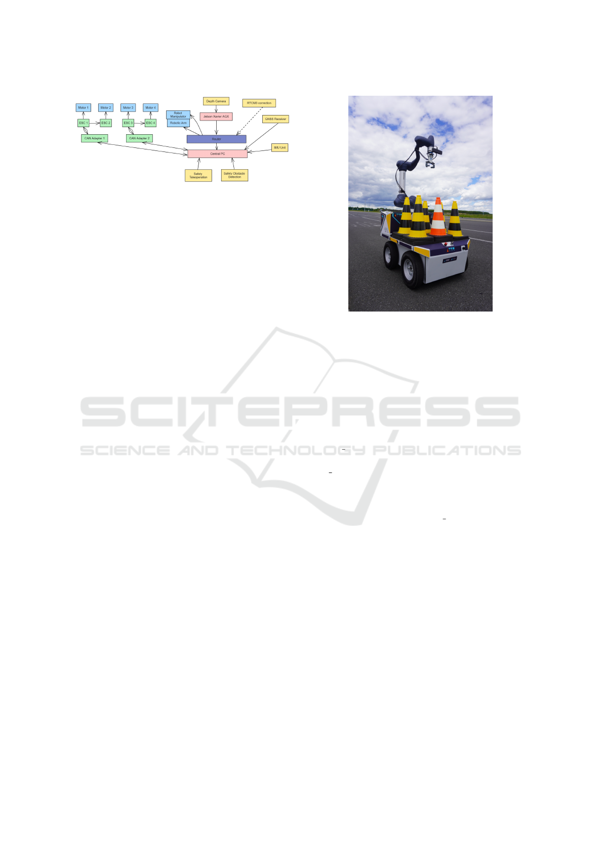
Figure 1: Block diagram of the robot platform for traffic
cone manipulation.
the 5G router. The end effector, which is affixed to the
arm, interfaces over the same network, allowing uni-
fied control and coordination within the ROS 2 frame-
work.
Inertial data is acquired through an on-board IMU
unit, connected via a direct serial interface to the cen-
tral PC. Alongside, a high-precision GNSS receiver
also communicates via serial and supports Real-Time
Kinematic (RTK) corrections using RTCM3 mes-
sages received through the router using the NTRIP
protocol. As far as our current setup, position is pro-
vided by the GNSS-RTK system, while initial orien-
tation is determined based on the IMU’s integrated
magnetometer.
For perception, a stereo depth camera is connected
to a dedicated NVIDIA Jetson Xavier AGX computer.
This PC dedicated for the machine’s vision is net-
worked with the central industrial computer via the
5G router, allowing high-bandwidth data transfer and
distributed processing. This setup is intended to de-
tect traffic cones using neural networks assigning a
collaborative robotic arm to approach the traffic cone
(Holl
´
osi et al., 2021).
Altogether, the robot’s system design (Figure 1)
balances modularity and centralization, leveraging
modern industrial and robotics standards to ensure re-
liability, scalability, and ease of integration with col-
laborative automation workflows.
4 HUMAN-MACHINE
INTERFACE
To enable intuitive human-robot interaction for traffic
cone manipulation, we developed a custom user in-
terface panel in Foxglove Studio (Foxglove, 2024), a
modern, browser-based visualization tool for ROS 2.
Unlike traditional approaches, our solution allows op-
erators to interactively define waypoints, assign speed
profiles, and trigger manipulation behaviors in real
time through a map-based graphical interface.
Figure 2: Heavy duty robot platform for traffic cone manip-
ulation.
4.1 Panel Overview
The panel was implemented as a Foxglove Panel
Extension using React and TypeScript. It inte-
grates directly with ROS 2 via the Foxglove Web-
Socket bridge, enabling seamless communication
with the robot using standard ROS 2 message types.
The robot’s trajectory is defined by a /textttge-
ometry msgs/msg/PoseArray message, which speci-
fies the ordered list of waypoints. An associated
std msgs/msg/Float32MultiArray message pro-
vides corresponding speed values for each waypoint.
Operator commands, such as starting or stopping
the robot, and triggering cone placement routines,
are handled via ROS 2 std srvs/srv/Trigger
services.
The panel (Figure 3) presents a live, zoomable
map view centered on a user-specified virtual ori-
gin, overlaid with dynamic visualizations of way-
points, color-coded trajectory lines, and any previ-
ously placed cones. The design ensures real-time
feedback, improves operator awareness, and enables
seamless integration into field deployments.
4.2 Functionality
Through the panel, users can interactively define a
trajectory by clicking directly on the map to specify
waypoints. These waypoints are immediately visual-
ized as traffic cone-shaped markers. Based on traffic
cone locations, a simple trajectory is planned locally.
The placed traffic cones are interconnected and way-
points are defined along these sections at constant dis-
Curvature-Constrained Motion Planning and Control for Traffic Cone Manipulation Robot
319
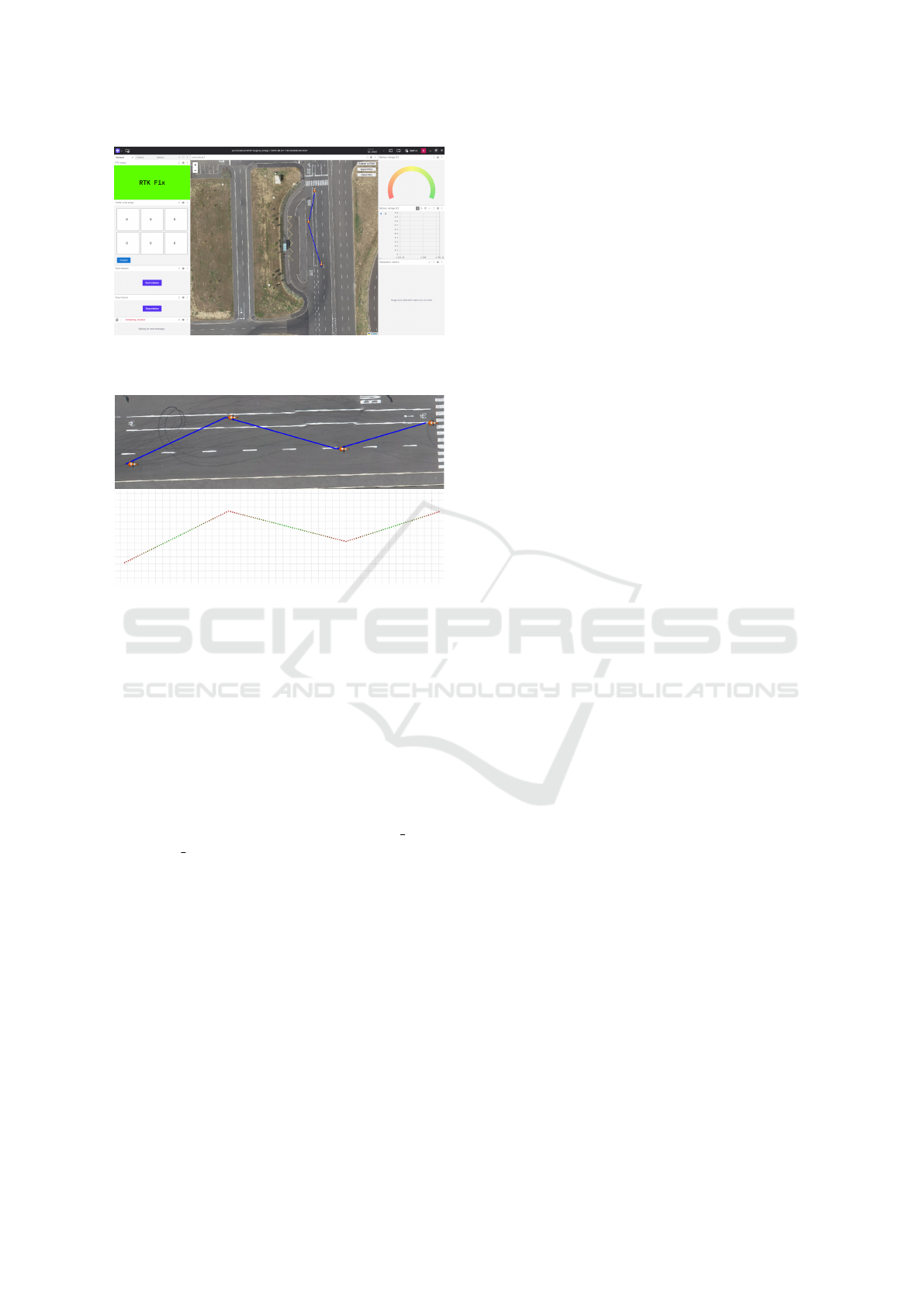
Figure 3: Custom Foxglove Studio panel for traffic cone
placement and mission control.
Figure 4: Waypoint array including velocity information
generated based on the requested traffic cone placement pat-
tern.
tances. For each waypoint, a speed value can be as-
signed. The discrete longitudinal velocity values are
computed locally using a trapezoidal profile between
traffic cone locations, reaching zero at waypoints des-
ignated for cone placement (Figure 4). After manu-
ally assigning traffic cone locations, the user can fi-
nalize the editing by clicking on a dedicated button,
publishing the waypoint array and speed values to the
robot. The interface includes controls for initiating
and halting robot motion, mapped to /start robot
and /stop robot ROS 2 services. As the user modi-
fies the waypoint list or adjusts speed values, the panel
does not continuously publish updated trajectory data
to avoid unexpected overlays between multiple track
layouts.
4.3 Design Considerations
Foxglove Studio was selected for its modern architec-
ture and flexibility in user interface design. It runs in
any modern web browser without requiring local ROS
installation, making it especially suitable for remote
operation and distributed teams. The support for full
React-based customization enabled us to tailor the in-
terface precisely to the needs of the cone manipulation
task, reducing cognitive load on the operator. Real-
time communication with ROS 2 topics and services
ensures that the panel remains highly responsive, even
when modifying paths during mission execution.
Furthermore, the web-based deployment model
allows the panel to be hosted on a central machine,
enabling access from any network-connected device.
This facilitates supervisory control by multiple users
and aligns well with semi-autonomous or mixed-
initiative mission frameworks.
5 TRAJECTORY PLANNING
The trajectory planning strategy employed in this
system is deliberately operator-driven, focusing on
simplicity, direct control, and real-time feedback.
Rather than relying on automated path planning al-
gorithms, the robot follows a trajectory defined man-
ually through the custom Foxglove panel. This ap-
proach empowers human operators to design and edit
robot paths based on environmental context, task re-
quirements, or safety considerations, while keeping
the planning layer lightweight and adaptable.
5.1 Waypoint-Based Path Specification
The planned trajectory consists of a sequence of spa-
tial waypoints, each representing a desired robot pose
(position and orientation) in two-dimensional space.
In addition to geometric position, each waypoint is
associated with a scalar speed value that modulates
the robot’s linear velocity as it approaches the target.
As mentioned before, these speed values serve
both, as velocity commands and as semantic mark-
ers. In particular, a speed value of zero designates
the waypoint as a logical stop point. When the robot
reaches such a waypoint, it initiates a controlled pause
and triggers a predefined action—typically the place-
ment or retrieval of a traffic cone. After completing
the action and waiting for a configurable duration, the
robot resumes motion toward the next target in the se-
quence.
This combination of spatial and behavioral encod-
ing within the waypoint list enables rich, event-driven
trajectories to be constructed with minimal interface
complexity.
6 MOTION CONTROLLER
The mobile robot used in this system is physically
incapable of performing orientation changes with-
out longitudinal movement due to its size and wheel
ICINCO 2025 - 22nd International Conference on Informatics in Control, Automation and Robotics
320

configuration dictated by stability requirements. As
a result, traditional point-turn alignment strategies
commonly used in indoor robotics are infeasible.
To address this limitation, we designed a curvature-
constrained motion controller that enables the robot
to follow arbitrary waypoint sequences using only
smooth, forward-facing movements with bounded an-
gular curvature (Paden et al., 2016). This controller
forms the core of the system’s low-level autonomy,
enabling reliable execution of the trajectories defined
through the user interface.
6.1 Control Architecture
The controller is implemented as a discrete-time,
event-driven finite-state machine (Han
ˇ
zi
ˇ
c et al., 2013)
with three operational states: ALIGN, GOTO, and
PAUSE. These states reflect the primary behaviors
needed to execute a semantically rich waypoint-based
trajectory while respecting the robot’s kinematic con-
straints.
In the ALIGN state, the robot adjusts its heading
toward the current waypoint target. However, unlike
conventional in-place rotation strategies, this align-
ment is performed using a gentle forward arc. The
robot moves slowly while modulating its angular ve-
locity based on the heading error, constrained by a
maximum allowable curvature that reflects the robot’s
minimum turning radius.
In the GOTO state, the robot proceeds toward the
waypoint, continuing to correct its heading dynam-
ically. If the orientation error is too large, forward
velocity is reduced to ensure stability. Otherwise, the
robot follows a curvature-constrained path that blends
translation and heading correction into a single mo-
tion profile.
In the PAUSE state, the robot has reached a way-
point marked with a zero-speed command. It stops
moving, triggers traffic cone placement and remains
stationary for a configurable delay before proceeding
to the next waypoint. During this delay, the robot
can perform application-specific tasks, such as plac-
ing traffic cones, before continuing to the next way-
point.
State transitions are triggered by geometric prox-
imity to the target waypoint (position tolerance),
alignment within an angular threshold (heading toler-
ance), or time-based conditions during pauses. The
robot continues to cycle through these states until
all waypoints have been executed or an external stop
command is received.
6.2 Curvature-Based Control Law
To ensure smooth and kinematically feasible motion,
angular velocity is computed using a curvature-based
control strategy. Let (x, y,θ) denote the current pose
of the robot, and let (x
w
,y
w
) be the position of the tar-
get waypoint. The Euclidean distance to the waypoint
is given by:
d =
q
(x
w
− x)
2
+ (y
w
− y)
2
(1)
The desired heading is computed using the two-
argument arctangent function (Siciliano et al., 2009):
θ
d
= atan2(y
w
− y,x
w
− x) (2)
To compute a smooth angular error, we use the
wrapped angle difference:
∆θ = atan2(sin(θ
d
− θ),cos(θ
d
− θ)) (3)
From the heading error and distance, we compute
an instantaneous curvature κ:
κ =
∆θ
max(d,ε)
(4)
where ε is a small positive constant used to prevent
division by zero at short distances.
To respect the robot’s physical turning limits, the
curvature is clamped to a maximum value κ
max
=
1
R
min
, where R
min
is the minimum turning radius
(Thrun et al., 2005):
κ ← clip(κ,−κ
max
,κ
max
) (5)
The final angular velocity command ω is com-
puted by scaling curvature with the linear velocity v:
ω = κ · v (6)
This formulation ensures that the robot never ex-
ceeds its curvature constraints while continuously ad-
justing its heading toward the waypoint. It also al-
lows the robot to follow smooth trajectories without
the need for stopping or in-place rotation, which is
particularly important given its limited turning capa-
bilities.
6.3 Behavior at Stop Points
When the controller detects that the robot has reached
a waypoint with an assigned speed of zero, it en-
ters the PAUSE state. Here, it initiates a service call
to trigger a predefined manipulation action—such as
triggering the actuator to place a cone—and begins a
countdown timer. The duration of the pause is config-
ured as a static parameter. Once the pause concludes,
the controller transitions back to the ALIGN state and
proceeds toward the next waypoint.
The controller has been implemented as presented
by (Algorithm 1).
Curvature-Constrained Motion Planning and Control for Traffic Cone Manipulation Robot
321

Data: Current robot pose (x,y,θ), waypoint
(x
w
,y
w
), min. turning radius R
min
Result: Velocity command (v,ω)
Compute dx ← x
w
− x, dy ← y
w
− y;
Compute d ←
p
dx
2
+ dy
2
;
Compute desired heading θ
d
← atan2(dy,dx);
Compute yaw error
∆θ ← atan2(sin(θ
d
− θ),cos(θ
d
− θ));
if state = ALIGN then
if |∆θ| < heading tolerance then
state ← GOTO;
end
else
v ← 0.1;
curv ← ∆θ/ max(d,0.1);
curv ←
clip(curv,−1/R
min
,+1/R
min
);
ω ← curv · v;
return (v,ω);
end
else if state = GOTO then
if d < position tolerance then
if speed = 0.0 then
state ← PAUSE, start timer, stop
robot;
end
else
state ← ALIGN, index ← index
+1;
end
end
else
v ← min(linear speed,speed);
curv ← ∆θ/ max(d,0.1);
curv ←
clip(curv,−1/R
min
,+1/R
min
);
ω ← curv · v;
return (v,ω);
end
else if state = PAUSE then
if not yet triggered then
Call trigger service;
end
if pause duration elapsed then
if more waypoints then
state ← ALIGN, index ← index
+1;
end
else
state ← IDLE, stop robot;
end
end
end
Algorithm 1: Curvature-based motion control.
7 EXPERIMENTS AND
EVALUATION
To validate the proposed curvature-constrained tra-
jectory execution system and assess the effectiveness
of the custom Foxglove-based operator interface, we
conducted two main experiments. The first was car-
ried out in simulation to verify controller behavior un-
der idealized conditions, while the second involved
deploying the system on a physical robot platform
equipped with a traffic cone manipulation mecha-
nism.
7.1 Simulation-Based Validation
The initial evaluation phase was conducted in a
custom-built simulator designed to emulate the mo-
tion dynamics of the real robot. This simulator
subscribed to velocity commands published on the
/cmd vel ROS 2 topic and generated corresponding
tf transformations, effectively mimicking the behav-
ior of the physical platform in a controlled ROS 2
environment. This setup enabled the rapid iterative
development of the controller logic and tuning of key
parameters, including linear speed, angular gain, and
heading and position tolerances, without the risk or
time constraints associated with physical trials.
The simulator confirmed that the curvature-
constrained controller is capable of accurately follow-
ing waypoint sequences with non-zero turning radii.
After several rounds of tuning, the robot success-
fully executed multi-segment paths while complying
with the minimum turning radius constraint. The
ALIGN, GOTO, and PAUSE state transitions behaved
as expected, and the robot consistently stopped and
resumed at designated zero-speed waypoints. This
stage also allowed us to refine speed profiling strate-
gies and verify that orientation interpolation across in-
terpolated poses yielded smooth heading transitions.
7.2 Deployment on Real Robot
Following successful simulation trials, the complete
system, including the custom Foxglove panel, GNSS-
RTK localization, and the motion controller was de-
ployed on the physical robot. The platform was
equipped with a manipulator capable of placing stan-
dard traffic cones retrieved from predefined onboard
storage locations. Field tests were conducted in out-
door environments with unobstructed GNSS visibility
and a stable RTK base station connection.
In practice, the system demonstrated reliable per-
formance on simple track layouts such as straight
lines and broad arcs. Using the Foxglove panel,
ICINCO 2025 - 22nd International Conference on Informatics in Control, Automation and Robotics
322
the operator interactively defined and published cone
placement trajectories, which the robot executed with
minimal supervision. The use of a triangular speed
profile for interpolated segments enabled smooth de-
celeration near stopping points, contributing to con-
sistent placement accuracy.
To assess the overall system accuracy, including
the robot platform and the point-to-point PID con-
troller, the robot’s ability to follow goal points was
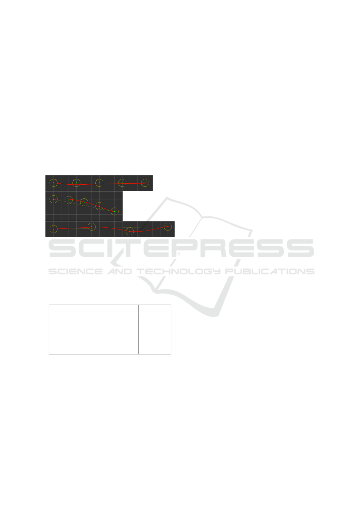
evaluated. Figure 5 illustrates three test scenarios: a
straight line of five waypoints spaced 3m apart, a gen-
tle arc defined by five points, and a zig-zag pattern
consisting of four waypoints. In the figure, the red
line represents the executed trajectory, while green
dots denote target waypoints, each surrounded by a
yellow circle with a 0.5m radius for visual clarity.
Figure 5: Test waypoint constellations (straight line, slight
arc, zig-zag pattern).
These constellations were repeated multiple times,
and after reaching 25 waypoints in total, the achieved
accuracy has been evaluated. The results are pre-
sented by Table 1.
Table 1: Waypoint following accuracy metrics.
Metric Value (m)
Mean Absolute Error (MAE) 0.117
Root Mean Square Error (RMSE) 0.146
Standard Deviation 0.089
Maximum Error 0.260
Minimum Error 0.000
Median 0.080
7.3 Limitations and Edge Cases
The described mobile robot for traffic cone placement
defines a number of requirements in order to be oper-
ational. These requirements include good GNSS cov-
erage and the availability of an RTK base. While the
system reliably executes cone placement routines un-
der nominal conditions, certain edge cases pose chal-
lenges. The controller assumes that all waypoints are
reachable via curvature-feasible paths. If the opera-
tor places a cone behind the robot or defines tightly
spaced waypoints that violate the robot’s minimum
turning radius, the robot may be unable to execute
the intended motion. Currently, such scenarios re-
quire trajectory redefinition. Similarly, closely spaced
cones may result in overlapping manipulation zones,
as the dimensions of the robot platform are not taken
into consideration automatically. Solving these edge
cases was out of the scope of this work, and cur-
rently are mitigated by defining policies for traffic
cone placement.
8 CONCLUSION AND FUTURE
WORK
This paper presented a fully integrated robotic sys-
tem designed for automatic traffic cone manipulation
in semi-structured outdoor environments. The plat-
form combines a high-load skid-steer mobile base,
GNSS-RTK localization, a curvature-constrained mo-
tion controller, and a browser-based planning inter-
face to achieve precise waypoint tracking and context-
aware task execution. The system emphasizes modu-
larity and real-world feasibility by leveraging ROS 2,
real-time communication networks, and industrial-
grade components such as CAN-driven ESCs and an
on-board robotic manipulator.
Our experimental results demonstrate that the pro-
posed control and planning architecture is capable of
reliably executing waypoint-defined cone manipula-
tion tasks even under curvature constraints imposed
by the platform’s limited turning capabilities. The
combination of a customized Foxglove Studio panel
and a curvature-aware trajectory controller enables
seamless operator interaction and safe execution of
manipulation routines.
Future work will focus on several enhancements
aimed at increasing the system’s reliability while ad-
dressing the previously identified edge cases. First,
we plan to integrate dual-antenna GNSS-RTK hard-
ware to obtain accurate heading estimates that are in-
dependent of magnetic disturbances and IMU drift,
even at low speeds or during standstill. Secondly, we
intend to develop a software module to systematically
handle edge cases arising from suboptimal or infeasi-
ble cone placement. By assigning unique indices to
each cone and maintaining an execution queue, the
robot will be able to defer manipulation tasks that
are temporarily unreachable—such as cones located
at sharp backward angles or within physically con-
strained regions—and proceed with constructing the
remainder of the track. Deferred tasks can then be re-
visited once a more favorable pose or configuration is
reached. This approach will explicitly account for the
Curvature-Constrained Motion Planning and Control for Traffic Cone Manipulation Robot
323

physical dimensions and kinematic constraints of the
robot platform. In the longer term, we aim to enhance
the graphical user interface by introducing a mod-
ule that automatically assigns cone positions based on
input parametric drawings and high-level parameters
such as desired inter-cone spacing. We also envision a
dynamic placement strategy that enables the robot to
deploy cones while in motion, thereby eliminating the
need for full stops and improving overall operational
efficiency and task throughput.
ACKNOWLEDGEMENTS
This research was supported by the European Union
within the framework of the National Laboratory for
Autonomous Systems (RRF-2.3.1-21-2022-00002).
REFERENCES
Foxglove (2024). Foxglove studio. Accessed: 2025-06-07.
Fragapane, G., de Koster, R., Sgarbossa, F., and Strandha-
gen, J. O. (2021). Planning and control of autonomous
mobile robots for intralogistics: Literature review and
research agenda. European Journal of Operational
Research, 294(2):405–426.
Han
ˇ
zi
ˇ
c, F., Jezernik, K., and and, S. C. (2013). Mechatronic
control system on a finite-state machine. Automatika,
54(1):126–138.
Hartzer, J. and Saripalli, S. (2020). Autocone: An omni-
directional robot for lane-level cone placement. In
2020 IEEE Intelligent Vehicles Symposium (IV), page
1663–1668. IEEE.
Holl
´
osi, J., Mark
´
o, N., and Ballagi,
´
A. (2021). Forga-
lomtechnikai terel
˝
o b
´
oja
´
eszlel
´
esen alapul
´
o poz
´
ıci
´
o
´
es orient
´
aci
´
o meghat
´
aroz
´
asa [determining the position
and orientation of traffic cones based on detection].
In Digit
´
alis J
´
arm
˝
uipari Kutat
´
asok a Sz
´
echenyi Istv
´
an
Egyetemen - Konferenciakiadv
´
any 2021 [Digital Au-
tomotive Research at Sz
´
echenyi Istv
´
an University -
Conference Proceedings 2021], pages 56–63.
Hong Kong Highways Department (2019). Robot system
for placement and collection of traffic cones and warn-
ing lanterns at high speed roads. Accessed: 2025-05-
28.
Krecht, R. and Ballagi,
´
A. (2022). Tesztp
´
alya kiszolg
´
al
´
as
´
ara
alkalmas auton
´
om robotplatform g
´
ep
´
eszeti tervez
´
ese
[mechanical design of an autonomous robot plat-
form for test track support]. In Mobilit
´
as
´
es
k
¨
ornyezet: J
¨
ov
˝
oform
´
al
´
o j
´
arm
˝
uipari kutat
´
asok konfer-
enciakiadv
´
any [Mobility and Environment: Confer-
ence Proceedings on Future-Shaping Automotive Re-
search], pages 220–232. 2022. novemberi konferen-
cia.
Paden, B.,
ˇ
C
´
ap, M., Yong, S. Z., Yershov, D., and Fraz-
zoli, E. (2016). A survey of motion planning and con-
trol techniques for self-driving urban vehicles. IEEE
Transactions on Intelligent Vehicles, 1(1):33–55.
Pfrommer, J., B
¨
omer, T., Akizhanov, D., and Meyer, A.
(2024). Sorting multibay block stacking storage sys-
tems.
Siciliano, B., Sciavicco, L., Villani, L., and Oriolo, G.
(2009). Robotics: Modelling, Planning and Control.
Springer, London.
Thrun, S., Burgard, W., and Fox, D. (2005). Probabilistic
Robotics. MIT Press, Cambridge, MA.
ZalaZONE Research and Innovation (2023). Innovation
in motion – autonomous systems national laboratory
demonstration day. https://research- and-innovatio
n.zalazone.hu/en/innovation-in-motion-autonomou
s-systems-national-laboratory-demonstration-day/.
Accessed: 2025-05-30.
ICINCO 2025 - 22nd International Conference on Informatics in Control, Automation and Robotics
324
