
A New Sliding Mode Control Proposal with a Clegg Integrator for a
Mobile Manipulator
Pablo Proa
˜
no
a
, Paulo Leica
b
and Gabriela Andaluz
c
Escuela Polit
´
ecnica Nacional, Departamento de Automatizacion y Control Industrial, Quito, Ecuador
Keywords:
Mobile Manipulator, Sliding Mode Control, Clegg Integrator, Trajectory Tracking, Discontinuous Control,
Chattering Reduction, Nonlinear Control.
Abstract:
This article presents a novel control strategy for trajectory tracking in mobile manipulators. The proposed
method combines a conventional Sliding Mode Controller (SMC) with a reset-based integrator, specifically
a Clegg integrator, applied to the discontinuous component of the sliding surface. The system under study
consists of a mobile platform with dynamic behavior and a robotic arm modeled kinematically. The main
objective is to improve tracking performance and reduce control signal oscillations, particularly under abrupt
reference changes and external disturbances. A reference trajectory with an inclined square shape is used
to challenge the controller with sudden directional transitions. To evaluate the effectiveness of the proposed
approach, both the classical SMC and the SMC+Clegg controllers are implemented and tested under the
same conditions. The performance is analyzed using standard indices such as Integral Square Error (ISE),
Integral Absolute Error (IAE), and Total Variation of the control signal (TVu). Results show that the proposed
controller achieves improved trajectory tracking with reduced overshoot and chattering, while maintaining
robustness to disturbances. Stability is formally demonstrated using Lyapunov theory. The positive impact of
the Clegg integrator is highlighted in the discontinuous control component, allowing for reduced control effort
without compromising tracking quality or disturbance rejection.
1 INTRODUCTION
The modeling of mobile manipulators is commonly
performed using state-space representations, where
inverse Jacobian matrices are employed to compute
the joint velocities required to follow a desired end-
effector trajectory. Since the mobile platform typi-
cally has greater mass than the robotic arm, a dynamic
model is used for the base and a kinematic model for
the manipulator to simplify the formulation while pre-
serving accuracy (Haddadin et al., 2022; Widhiada
et al., 2020; Delgado et al., 2022). Reference trajec-
tories with abrupt changes are often applied to test
the robustness and reactivity of controllers under de-
manding conditions (You et al., 2019; Kemp et al.,
2022).
A wide range of control techniques has been pro-
posed for mobile manipulators, including PID, null-
space optimization, fuzzy logic, and sliding mode
control (SMC) (Salinas et al., 2018; Moreno et al.,
a
https://orcid.org/0000-0002-6902-7151
b
https://orcid.org/0000-0002-5385-1920
c
https://orcid.org/0000-0002-1822-6943
2021). More recently, hybrid control approaches
have been explored to improve interaction perfor-
mance and adaptability, incorporating learning-based
impedance tuning (Zhao et al., 2022) and coordinated
actuation mechanisms (Gan et al., 2022). PID con-
trollers are extensively used in industry due to their
simplicity and effectiveness, although in robotic ap-
plications they are often embedded into hybrid strate-
gies (Zangina et al., 2020; Maung et al., 2024). A
key limitation of PID controllers lies in the integral
windup phenomenon, which can degrade system per-
formance by introducing overshoots and increasing
settling times (Hitit et al., 2023; Okelola et al., 2020;
Chaudhary, 2024).
Reset-based techniques have emerged to address
this issue. One notable solution is the Clegg in-
tegrator (CI), a nonlinear integrator that resets its
state when the error derivative crosses zero. The
CI reduces the accumulation of the integral term,
thereby limiting overshoot and improving transient
performance (Beerens et al., 2022; Gholipour et al.,
2015; Kolar and Lazar, 2021). Recent developments
have extended this concept through soft-reset con-
Proaño, P., Leica, P. and Andaluz, G.
A New Sliding Mode Control Proposal with a Clegg Integrator for a Mobile Manipulator.
DOI: 10.5220/0013719900003982
Paper published under CC license (CC BY-NC-ND 4.0)
In Proceedings of the 22nd International Conference on Informatics in Control, Automation and Robotics (ICINCO 2025) - Volume 2, pages 301-308
ISBN: 978-989-758-770-2; ISSN: 2184-2809
Proceedings Copyright © 2025 by SCITEPRESS – Science and Technology Publications, Lda.
301

trollers, which approximate hard-reset behavior using
continuous-time differential inclusions. These con-
trollers preserve passivity properties and offer im-
proved stability guarantees under convex Lyapunov
conditions, facilitating their application in robotic
systems (Le and Teel, 2021; Teel, 2022). . In re-
cent work by Proa
˜
no et al. (Proa
˜
no et al., 2024), the
use of a Clegg integrator in a PID-type sliding surface
demonstrated faster settling, reduced chattering, and
improved overall performance compared to conven-
tional SMC and PID strategies. The reset action was
shown to affect only the discontinuous component of
the SMC, resulting in a smoother control signal with-
out compromising the system’s robustness.
Sliding Mode Control remains a robust strategy
for handling modeling uncertainties and external dis-
turbances. It consists of a continuous term that
maintains system convergence on the sliding sur-
face and a discontinuous term responsible for driv-
ing the state toward it. The latter, however, tends
to introduce high-frequency oscillations, or chatter-
ing, which several studies have sought to mitigate us-
ing smoothed switching functions and hybrid surfaces
(Gude et al., 2024; Demim et al., 2023; Li et al.,
2024). Recent advancements have further explored
chattering reduction through higher-order and adap-
tive SMC strategies (V and Manthati, 2024), as well
as the use of chattering-attenuation disturbance ob-
servers (CADOB), which effectively suppress high-
frequency components in the disturbance estimation
without degrading control performance (Yim et al.,
2023).
This paper proposes a sliding mode control strat-
egy that incorporates a Clegg-type integrator into the
sliding surface. The reset action aims to mitigate
windup, reduce overshoot, and improve settling time.
The controller is implemented on a mobile manipu-
lator and evaluated under setpoint changes and exter-
nal disturbances. Performance indices are calculated
to compare the proposed method with conventional
strategies. The main contributions include improved
response time, reduced overshoot, enhanced recovery
from disturbances, and ease of implementation in sys-
tems that already use PID architectures.
2 MOBILE MANIPULATOR
MODEL
Before implementing the proposed control strategies,
it is essential to understand the structure and behavior
of the mobile manipulator. This system consists of a
mobile platform, modeled using a dynamic approach,
and a robotic arm, described through a kinematic
model. This section presents both models, which en-
able an accurate representation of the system’s evolu-
tion in response to control signals and reference tra-
jectories.
A graphical representation of the mobile manipu-
lator used in the present work is shown in Figure 1.
Figure 1: Mobile manipulator with three degrees of free-
dom, (Vizuete et al., 2017).
Where l
m
represents the vertical distance from the
ground to the base of link 1 of the manipulator; l
1
,
l
2
, and l
3
are the lengths of the manipulator links; a
denotes a point of interest introduced to eliminate the
non-holonomic constraint; and b is the distance from
the center of the mobile platform to link 1. The pa-
rameter a has no physical structure but is geometri-
cally defined to lift the non-holonomic restriction of
the platform’s motion model. The variables θ
1
, θ
2
,
and θ
3
correspond to the rotation angles of links l
1
,
l
2
, and l
3
, respectively. The coordinates x and y rep-
resent the position of the mobile robot’s base, and ψ
denotes its orientation, while u and ω represent the
linear and angular velocities of the mobile platform,
respectively. Finally, x
ee
, y
ee
, and z
ee
define the po-
sition of the end-effector with respect to the origin of
the coordinate system.
The position of the end-effector (x
ee
, y
ee
, z
ee
) as
a function of the system’s angles and parameters is
computed using the following expressions:
x
ee
= x + b cos(ψ)
+ cos(θ
1
+ ψ)(l
2
cos(θ
2
) + l
3
cos(θ
2
+ θ
3
))
(1)
y
ee
= y + b sin(ψ)
+ sin(θ
1
+ ψ)(l
2
cos(θ
2
) + l
3
cos(θ
2
+ θ
3
))
(2)
z
ee
= l
1
+ l
m
+ l
2
sin(θ
2
) + l
3
sin(θ
2
+ θ
3
) (3)
The kinematic behavior of the mobile platform is
described by the following equations:
˙x = u cos ψ − aωsinψ (4)
˙y = u sin ψ + aωcos ψ (5)
ICINCO 2025 - 22nd International Conference on Informatics in Control, Automation and Robotics
302

˙
ψ = ω (6)
Where x and y denote the position of the mobile
robot base, and ψ represents its orientation. The vari-
able u corresponds to the linear velocity of the mobile
platform, while ω denotes its angular velocity.
The kinematics of the mobile manipulator h is de-
termined by:
˙
h
ee
= J
ee
˙q (7)
Where J
ee
is the Jacobian matrix that relates the
generalized velocities ˙q = [u, ω,
˙
θ
1
,
˙
θ
2
,
˙
θ
3
]
T
to the
Cartesian velocity of the end-effector. The vector
h
ee
= [x
ee
, y
ee
, z
ee
]
T
represents the Cartesian position
of the end-effector in the task space, and is used to
describe its spatial motion relative to the global coor-
dinate system.
The Jacobian matrix J
ee
, using the trigonometric
shorthand defined in the implementation, is given by:
J
ee
=
C
ψ
−aS
ψ
− bS
ψ
− S
θ
1
ψ
(l
2
C
θ
2
+ l
3
C
θ
2
θ
3
) −S
θ
1
ψ
(l
2
C
θ
2
+ l
3
C
θ
2
θ
3
) −C
θ
1
ψ
(l
2
S
θ
2
+ l
3
S
θ
2
θ
3
) −l
3
C
θ
1
ψ
S
θ
2
θ
3
S
ψ
aC
ψ
+ bC
ψ
+C
θ
1
ψ
(l
2
C
θ
2
+ l
3
C
θ
2
θ
3
) C
θ
1
ψ
(l
2
C
θ
2
+ l
3
C
θ
2
θ
3
) −S
θ
1
ψ
(l
2
S
θ
2
+ l
3
S
θ
2
θ
3
) −l
3
S
θ
1
ψ
S
θ
2
θ
3
0 0 0 l
2
C
θ
2
+ l
3
C
θ
2
θ
3
l
3
C
θ
2
θ
3
(8)
Where C
ψ
= cos(ψ) and S
ψ
= sin(ψ); C
θ
2
=
cos(θ
2
) and S
θ
2
= sin(θ
2
); C
θ
1
ψ
= cos(θ
1
+ ψ) and
S
θ
1
ψ
= sin(θ
1
+ ψ); and C
θ
2
θ
3
= cos(θ
2
+ θ
3
) and
S
θ
2
θ
3
= sin(θ
2
+ θ
3
).
Each row of J
ee
corresponds to a Cartesian direc-
tion of the end-effector (x
ee
, y
ee
, and z
ee
), while each
column is associated with one of the generalized ve-
locities: u (linear), ω (angular), and
˙
θ
1
,
˙
θ
2
,
˙
θ
3
(joint
velocities of the manipulator).
Given that the mass of the robotic arm is consider-
ably smaller than that of the mobile platform, a kine-
matic model is used for the arm and a dynamic model
for the mobile platform.
˙u
˙
ω
=
B
3
B
1
ω
2
−
B
4
B
1
u
−
B
5
B
2
uω −
B
6
B
2
ω
+
"
1
B
1
0
0
1
B
2
#
u
r
ω
r
(9)
Where [B] = [B
1
, B
2
, B
3
, B
4
, B
5
, B
6
]
T
is the vec-
tor of identified parameters of the robot, u
r
is the con-
trol input associated with the linear velocity of the
mobile platform, and ω
r
is the control input associ-
ated with its angular velocity.
The final model of the mobile manipulator is ob-
tained by combining the kinematic model of the arm,
presented in Eq. (7), with the dynamic model of the
mobile platform, given in Eq. (9). This results in the
complete representation summarized in Eq. (10).
˙x
ee
˙y
ee
˙z
ee
˙
ψ
˙u
˙
ω
=
uJ
11
+ ωJ
12
+
˙
θ
1
J
13
+
˙
θ
2
J
14
+
˙
θ
3
J
15
uJ
21
+ ωJ
22
+
˙
θ
1
J
23
+
˙
θ
2
J
24
+
˙
θ
3
J
25
uJ
31
+ ωJ
32
+
˙
θ
1
J
33
+
˙
θ
2
J
34
+
˙
θ
3
J
35
ω
B
3
B
1
ω
2
−
B
4
B
1
u +
1
B
1
u
r
−
B
5
B
2
uω −
B
6
B
2
ω +
1
B
2
ω
r
(10)
where J
mn
represents the elements of the Jacobian ma-
trix described in Eq. (8), which maps the generalized
velocities to the Cartesian velocity of the end-effector.
3 DESIGN OF THE PROPOSED
CONTROLLER
This section presents the development of the con-
trollers. First, a sliding mode controller for the mo-
bile manipulator is derived, and then the concept of
a Clegg integrator is incorporated into its sliding sur-
face.
3.1 Sliding Mode Controller for Mobile
Manipulator
To compute the control inputs, the inverse kinematics
of the mobile manipulator is calculated.
U = J
+
ee
˙
h
ee
(11)
Where U = [u
c
, ω
c
,
˙
θ
1
,
˙
θ
2
,
˙
θ
3
]
T
is the vector of
control inputs generated through inverse kinematics,
and J
+
ee
is the pseudoinverse of the Jacobian matrix
J
ee
, used to map the desired Cartesian velocity of the
end-effector to the generalized control inputs. The
pseudoinverse is computed using the Moore–Penrose
formulation as:
J
+
ee
= J
T
ee
(J
ee
J
T
ee
)
−1
(12)
As described in the previous section, a sliding
mode controller consists of a continuous component
U
C
and a discontinuous component U
D
. To compute
the continuous component, a sliding surface must first
be defined. In this work, a proportional-integral (PI)
type surface is used:
s = e
h
+ λ
1
Z
e
h
dt (13)
A New Sliding Mode Control Proposal with a Clegg Integrator for a Mobile Manipulator
303

Where e
h
is the tracking error, defined as the
difference between the desired trajectory and the
actual end-effector position, i.e., e
h
= h
d
− h
ee
=
[e
x
, e
y
, e
z
]
T
; h
d
represents the desired Cartesian tra-
jectory of the end-effector; and λ
1
is a positive tuning
parameter that determines the convergence rate of the
sliding surface.
To satisfy the sliding condition, the derivative of
the sliding surface must be equal to zero. Therefore,
the time derivative of Eq. (13) is computed as:
˙s = ˙e
h
+ λ
1
e
h
= 0 (14)
Since the tracking error is defined as e
h
= h
d
−h
ee
,
its time derivative is given by:
˙e
h
=
˙
h
d
−
˙
h
ee
(15)
Substituting Eq. (15) into Eq. (14), the sliding sur-
face derivative becomes:
˙s =
˙
h
d
−
˙
h
ee
+ λ
1
e
h
= 0 (16)
Solving for
˙
h
ee
yields:
˙
h
ee
=
˙
h
d
+ λ
1
e
h
(17)
Equation (17) provides the desired Cartesian ve-
locity of the end-effector required to stay on the slid-
ing surface. By substituting this expression into the
inverse kinematics relation in Eq. (11), the continu-
ous component of the sliding mode control law is ob-
tained as:
U
C
= J
+
ee
˙
h
d
+ λ
1
e
h
(18)
To obtain the discontinuous component of the con-
troller, the Lyapunov stability concept is directly ap-
plied.
According to Lyapunov’s direct method, if there
exists a scalar function V , continuously differentiable
and positive definite, such that its time derivative
along the system trajectories
˙
V is negative definite,
then the equilibrium point at the origin is globally
asymptotically stable.
Let V =
1
2
s
T
s, which satisfies V > 0 for all s ̸= 0,
since s
T
s represents the squared norm of the vector s.
If s = 0, then V = 0, as the norm of the zero vector
is zero. The time derivative of V is given by
˙
V =
1
2
˙s
T
s + s
T
˙s
= s
T
˙s.
The error derivative in Eq. (14) is decomposed
as ˙e
h
=
˙
h
d
−
˙
h
ee
. Then, using the expression from
Eq. (7),
˙
h
ee
is replaced by J
ee
U, and this substitution
is used to rewrite the sliding surface derivative.
˙
V = s
T
˙
h
d
− J
ee
U + λ
1
e
h
(19)
If U
SMC
is considered as the sum of its continuous
and discontinuous components, that is, U
SMC
= U
C
+
U
D
, and the expression for U
C
from Eq. (18) is used,
the following is obtained:
˙
V = −s
T
J
ee
U
D
(20)
To ensure that
˙
V < 0, the discontinuous compo-
nent is defined as:
U
D
= J
+
ee
k
D
sign(s) (21)
where k
D
is a positive scalar or diagonal gain matrix
that adjusts the intensity of the switching action. The
matrix J
+
ee
denotes the pseudoinverse of the Jacobian
matrix J
ee
, and is used to project the control action
from Cartesian space back to the generalized coordi-
nates of the system. This operation allows the gen-
eration of appropriate control inputs that achieve the
desired behavior of the end-effector in task space.
However, using the sign(s) function may cause
chattering and excessive effort in the actuators of the
mobile manipulator. Therefore, a smoothed version is
used instead:
U
D
= J
+
ee
k
D
s
∥s∥ + δ
(22)
where δ is a small positive scalar that smooths the
discontinuity and reduces chattering effects. A larger
value of δ increases the smoothness of the control sig-
nal but compromises the speed at which the system
reaches the reference.
Replacing the smoothed expression of U
D
into the
derivative of the Lyapunov function yields:
˙
V = −s
T
J
ee
J
+
ee
k
D
s
∥s∥ + δ
(23)
Assuming that J
ee
J
+
ee
≈ I, this simplifies to:
˙
V = −k
D
s
T
s
∥s∥ + δ
(24)
Since k
D
> 0, it follows that
˙
V < 0, which implies
that s → 0 as t → ∞. From (13), and by introducing
the change of variable ρ =
R
e
h
dt, we obtain:
0 =
˙
ρ + λ
1
ρ (25)
In order for the system solutionisfy ρ → 0, it is
required that λ
1
> 0. Consequently, ρ =
R
e
h
dt → 0,
which implies that e
h
→ 0 as t → ∞.
The complete control law can be expressed in a
compact form as:
U
SMC
= J
+
ee
˙
h
d
+ λ
1
e
h
+
k
D
s
∥s∥ + δ
(26)
3.2 Sliding Mode Control Proposal with
a Clegg Integrator
The approach proposed in this work uses a Clegg inte-
grator in the sliding surface. Figure 2 presents a block
ICINCO 2025 - 22nd International Conference on Informatics in Control, Automation and Robotics
304
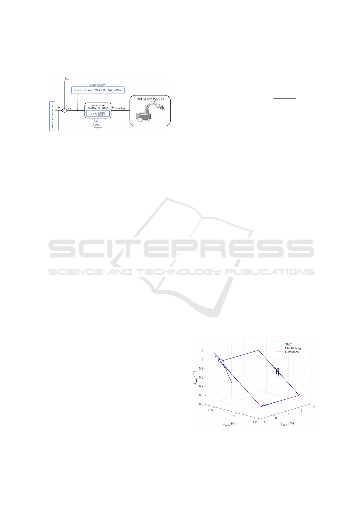
diagram of the overall control strategy, which will be
detailed in the following sections.
Figure 2: SMC+Clegg control scheme.
The resulting sliding surface, incorporating a
Clegg integrator, is expressed as:
s
Cl
= e
h
+ λ
1
K
Cl
Z
t
0
e
h
(ξ)dξ
+ (1 − K
Cl
)
Z
t
t
r
e
h
(ξ)dξ
!
(27)
Where K
Cl
is a scalar gain that determines the con-
tribution of the Clegg integrator in the sliding surface.
It must be bounded in the range 0 ≤ K
Cl
≤ 1, where
K
Cl
= 1 corresponds to a full Clegg integrator and
K
Cl
= 0 to a conventional integrator. The variable ξ
is used as the integration variable to avoid confusion
with the upper limit t, and represents the intermediate
time over which the error signal is integrated. The re-
set time t
r
is updated whenever the derivative of the
tracking error ˙e
h
crosses zero; this mechanism elimi-
nates the accumulation of past control actions and re-
sets the integrator, thereby reducing windup effects.
To avoid spurious resets caused by high-frequency
noise, a moving average filter with a window of five
sampling intervals was applied to ˙e
h
prior to evaluat-
ing the reset condition.
Since the continuous component was obtained
based on the sliding condition, which requires the
time derivative of the sliding surface to be zero, the
Clegg integrator has no effect on the continuous part
of the controller. This is because the integral term
in the sliding surface expression disappears when dif-
ferentiating. As a result, the continuous component
of a conventional SMC controller and that of the
SMC+Clegg controller are the same. Therefore, the
stability analysis of the continuous part presented in
the previous section also applies to the proposed con-
troller.
However, the discontinuous component of the
controller directly depends on the sliding surface ex-
pression, which includes the Clegg integrator. There-
fore, the effects of the Clegg integrator have a direct
impact on the discontinuous control action, influenc-
ing both the chattering behavior of the system and its
settling time.
The complete control law, using the Clegg-
integrated sliding surface, is defined as:
U
SMC+Clegg
= J
+
ee
˙
h
d
+ λ
1
e
h
+
k
D
s
Cl
∥s
Cl
∥ + δ
(28)
The simulation parameters used for the model and
controller are as follows: the manipulator link lengths
are l
1
= 0.4 m, l
2
= 0.25 m, and l
3
= 0.25 m; the
vertical offset is l
m
= 0.2 m; the distances a and b
are both set to 0.13 m. The dynamic coefficients
used in the model are B
1
= 0.2604, B
2
= 0.2509,
B
3
= −4.99 × 10
−4
, B
4
= 0.9965, B
5
= 0.00263, and
B
6
= 1.0768. The control parameters include a slid-
ing surface slope λ
1
= 28, Clegg integrator reset pro-
portion K
Cl
= 0.5, smoothing parameter δ = 0.8, and
sliding mode gain k
D
= 11.5.
4 RESULTS AND DISCUSSION
This section presents the results of the tests per-
formed. A single experiment was conducted, con-
sisting of trajectory tracking combined with an ex-
ternal disturbance to evaluate the performance of
the conventional SMC controller and the proposed
SMC+Clegg approach. The selected trajectory is an
inclined-square path that includes sharp corners and
sudden reference changes, designed to assess the con-
trollers’ performance under abrupt directional transi-
tions and varying orientations.
As shown in Figure 3, the results of the tracking
for the inclined-square trajectory are presented. The
reference trajectory is shown in red, the response us-
ing the conventional SMC controller is shown in blue,
and the response of the proposed SMC+Clegg inte-
grator in the sliding surface is shown in black.
Figure 3: Tracking results for the inclined-square trajectory.
A New Sliding Mode Control Proposal with a Clegg Integrator for a Mobile Manipulator
305
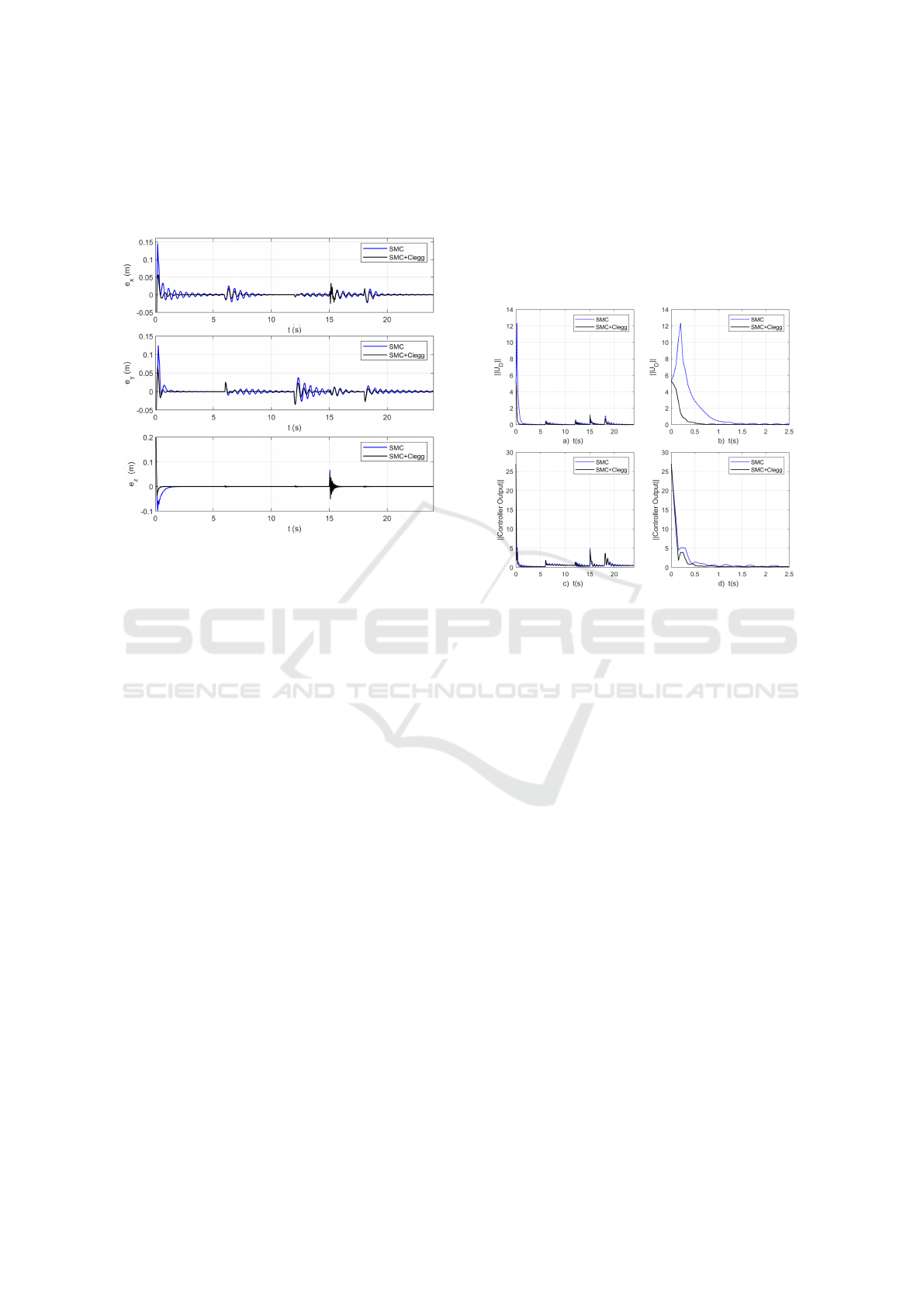
Figure 4 presents the tracking errors along the
three Cartesian axes for the inclined-square trajectory.
The effects of the disturbance introduced into the sys-
tem at t = 15 s can also be observed in the responses.
Figure 4: Tracking errors for the inclined-square trajectory.
Top: error in the x-axis; middle: error in the y-axis; bottom:
error in the z-axis.
As observed in the Figure 4, the introduction of
the Clegg integrator in the sliding surface reduces
both the amplitude and duration of the oscillations.
The proposed approach improves the system’s re-
sponse in terms of trajectory tracking and recovery
after disturbances in the inclined-square trajectory.
To highlight the impact of the proposed method
on the control action, Figure 5 shows the norm of the
control output vectors, with the conventional SMC
controller in blue and the SMC+Clegg controller in
black.
The greatest influence of the Clegg integrator oc-
curs in the sliding surface, which is directly associ-
ated with the discontinuous component of the con-
trol law. As shown in Figure 5(a), the norm of U
D
is significantly reduced when using the SMC+Clegg
controller, indicating a more moderate control effort
during transients. This reduction is more clearly ob-
served in the zoomed view in Figure 5(b), where sharp
variations are effectively attenuated. Figures 5(c)
and 5(d) present the norm of the total control signal
and its zoomed view, respectively, showing that the
benefits of the proposed strategy extend to the overall
control action, particularly during abrupt changes in
the reference or in the presence of disturbances.
It is important to clarify that, although the dis-
continuous term is bounded due to the smoothing pa-
rameter applied to the switching function, the integral
term in the sliding surface may still accumulate error
during persistent transients. This accumulation can
delay convergence and intensify the control action be-
fore correction occurs. By resetting the integral com-
ponent whenever the error derivative crosses zero, the
Clegg integrator mitigates this form of windup in the
sliding surface, contributing to faster recovery and
improved control smoothness during abrupt transi-
tions.
Figure 5: Norm of the controller vector: (a) discontinuous
component U
D
, (b) zoomed view of U
D
, (c) total control
signal, and (d) zoomed view of the total control signal.
Likewise, Figure 5(d) shows that noticeable dif-
ferences between both controllers emerge primarily
during abrupt reference changes or in the presence
of disturbances. This behavior aligns with expecta-
tions, since the discontinuous component—where the
Clegg integrator is applied—is activated mainly un-
der significant tracking errors. During steady-state
operation, when the system remains close to the ref-
erence, the control action is dominated by the contin-
uous component, leading to similar behavior for both
controllers.
To evaluate the performance of the controller,
three standard indices were used: the Integral Square
Error (ISE), the Integral Absolute Error (IAE), and
the Total Variation of the control signal (TVu). These
metrics were applied to quantify the tracking accuracy
and control effort of each controller. Table 1 summa-
rizes the results obtained for both controllers, includ-
ing the percentage improvement achieved by the pro-
posed SMC+Clegg controller relative to the conven-
tional SMC controller. Additionally, since the Clegg
integrator is applied in the discontinuous part of the
control law, the TVu was also computed specifically
for that component to assess its isolated effect on con-
trol smoothness.
ICINCO 2025 - 22nd International Conference on Informatics in Control, Automation and Robotics
306
Table 1: Performance comparison for the inclined-square
trajectory.
Metric SMC SMC+Clegg ∆ (%)
IAE 0.21846 0.12332 43.55
ISE 0.01685 0.01377 18.30
TVu 7.51519 6.52225 13.21
TVu (U
D
) 2.39366 1.40371 41.36
As evidenced by the results, the proposed
SMC+Clegg controller achieved notable improve-
ments in all performance indices. The IAE was re-
duced by over 43%, and the total variation of the
discontinuous control signal (U
D
) decreased by more
than 41%, indicating a smoother and more efficient
control effort. Although the reduction in ISE and
overall TVu was more moderate, improvements of
18% and 13%, respectively, still reflect enhanced
tracking precision and reduced control aggressive-
ness. Importantly, resetting the integral component
did not compromise the system’s ability to reject dis-
turbances. In this study, a reset proportion of 50%
(K
Cl
= 0.5) was employed, balancing convergence
speed with control signal smoothness. This value was
selected empirically based on iterative testing, as it
provided a satisfactory trade-off between responsive-
ness and chattering attenuation. Nonetheless, system-
atic tuning or optimization of K
Cl
may further im-
prove performance and is considered for future work.
5 CONCLUSIONS
This work presented a sliding mode control strategy
that incorporates a Clegg integrator into the sliding
surface. The controller was implemented on a mo-
bile manipulator combining the kinematic model of
the arm and the dynamic model of the platform.
The system was evaluated using an inclined-
square trajectory and external disturbances to test ro-
bustness. Compared to the conventional SMC, the
proposed controller showed improved performance,
with reduced overshoot duration and oscillations,
smoother control signals, and effective mitigation of
chattering. These improvements were reflected in the
IAE, ISE, and TVu indices.
Stability is formally ensured via Lyapunov’s direct
method. The Clegg integrator only affects the discon-
tinuous part of the control law, which is active mainly
during transient phases, leaving the continuous com-
ponent stable during steady-state.
Future work may include experimental validation
and extension to systems with higher complexity or
nonlinearities. It should be noted that the current re-
sults are limited to simulation only. Therefore, prac-
tical aspects such as sensor noise, actuator saturation,
and discretization effects must be considered in future
implementations, as they may affect the reset behav-
ior and control smoothness.
Additionally, this work focused exclusively on
the Clegg integrator due to its simplicity and
proven effectiveness. A comparative analysis with
other reset strategies—such as First-Order Reset
Elements (FORE) or Generalized Reset Elements
(GFORE)—was not conducted and remains an im-
portant direction for future research. Nonetheless, the
proposed strategy relies on standard Jacobian inver-
sion and integrator modification, which facilitates its
application in embedded systems with typical sensing
and actuation capabilities.
Moreover, extensions of sliding mode control
such as higher-order sliding mode (HOSMC) and
homogeneity-based designs were not considered in
this study. These approaches offer improved conver-
gence properties and enhanced robustness, and their
integration with reset-based strategies could further
improve system performance, representing a valuable
direction for future exploration.
REFERENCES
Beerens, R., Bisoffi, A., Zaccarian, L., Nijmeijer, H.,
Heemels, M., and van de Wouw, N. (2022). Reset
pid design for motion systems with stribeck friction.
IEEE Transactions on Control Systems Technology,
30(1):294–301.
Chaudhary, B. (2024). Anti-windup strategy for interval
positive linear systems with input saturation. Inter-
national Journal of Dynamics and Control, 12:2842–
2849.
Delgado, M., Morales, R., Garc
´
ıa, J., and P
´
erez, L. (2022).
Motion planning for mobile manipulators—a system-
atic review. Machines, 10(2):97.
Demim, F., Rouigueb, A., Belaidi, H., Messaoui, A. Z.,
Bensseghieur, K. L., Allam, A., Benatia, M. A., Nouri,
A., and Nemra, A. (2023). Smooth sliding mode
control based technique of an autonomous underwa-
ter vehicle based localization using obstacle avoid-
ance strategy. In Proceedings of the 20th Inter-
national Conference on Informatics in Control, Au-
tomation and Robotics (ICINCO 2023), pages 529–
537. SCITEPRESS – Science and Technology Publi-
cations.
Gan, D., Fu, J., Lin, H., Yang, H., Rastgaar, M., Min, B.-
C., and Voyles, R. (2022). Actuation-coordinated mo-
bile parallel robots with hybrid mobile and manipula-
tion functions. Journal of Mechanisms and Robotics,
14(4):041005.
Gholipour, E., Aref, M. M., and Fateh, M. M. (2015). 2-dof
pid with reset controller for 4-dof robot arm manip-
ulator. In 2015 3rd RSI International Conference on
A New Sliding Mode Control Proposal with a Clegg Integrator for a Mobile Manipulator
307

Robotics and Mechatronics (ICRoM), pages 704–709.
IEEE.
Gude, J. J., Di Teodoro, A., Agudelo, D., Herrera, M.,
Rinc
´
on, L., and Camacho, O. (2024). Sliding mode
control design using a generalized reduced-order frac-
tional model for chemical processes. Results in Engi-
neering, 24:103032.
Haddadin, S., Albu-Sch
¨
affer, A., and Hirzinger, G. (2022).
A holistic approach to reactive mobile manipulation.
IEEE Transactions on Robotics, 38(1):3–22.
Hitit, Z. Y.,
˙
Ismet Koc¸er, Kus¸, G., Arslan, N. Z., Dal,
E. P., and Koz, H. (2023). Optimal pid control
with anti-windup in neutralization process. Interna-
tional Advanced Researches and Engineering Jour-
nal, 7(3):138–145.
Kemp, C. C., Edsinger, A., Clever, H. M., and Matule-
vich, B. (2022). The design of stretch: A compact,
lightweight mobile manipulator for indoor human en-
vironments. In 2022 International Conference on
Robotics and Automation (ICRA), pages 3150–3157.
Kolar, A. and Lazar, M. (2021). Anti windup pid control
of discrete systems subject to actuator saturation. In
2021 60th IEEE Conference on Decision and Control
(CDC), pages 5104–5109, Austin, TX, USA. IEEE.
Le, J. H. and Teel, A. R. (2021). Passive soft-reset con-
trollers for nonlinear systems. In 2021 60th IEEE
Conference on Decision and Control (CDC), pages
5320–5325.
Li, X., Wang, Y., Liu, Y., Liu, Y., and Liu, Y. (2024). A
novel hybrid control strategy for a class of nonlinear
systems with input saturation. Heliyon, 10(9):e2590.
Maung, L. M. M., San, A. M., Myint, W. M., Win, W. Y.,
and Soe, M. T. (2024). Analysis of the pid con-
troller parameters for a surface mobility platform mo-
bile robot. PLATFORM - A Journal of Engineering,
8(2):29–40. Creative Commons CC BY 4.0.
Moreno, G. P., la Cruz, N. D. D., Ortiz, J. S., and Andaluz,
V. H. (2021). Human-robot collaborative control for
handling and transfer objects. In Applied Technolo-
gies, volume 1388 of Communications in Computer
and Information Science, pages 96–110. Springer.
Okelola, M. O., Aborisade, D. O., and Adewuyi, P. A.
(2020). Performance and configuration analysis
of tracking time antiwindup pid controllers. Jur-
nal Ilmiah Teknik Elektro Komputer dan Informatika
(JITEKI), 6(2):20–29.
Proa
˜
no, P., D
´
ıaz, R., Chill
´
an, C., Medina, J., Chamorro, W.,
and Zu
˜
niga, J. (2024). Sliding mode control proposed
using a clegg integrator for speed control of a three-
phase induction motor. In Proceedings of the XXXII
Conference on Electrical and Electronic Engineering,
volume 77, page 8. MDPI.
Salinas, L. R., Santiago, D., Slawi
˜
nski, E., Mut, V. A.,
Chavez, D., Leica, P., and Camacho, O. (2018). P+d
plus sliding mode control for bilateral teleoperation of
a mobile robot. International Journal of Control, Au-
tomation and Systems, 16(4):1927–1937.
Teel, A. R. (2022). Continuous-Time Implementation of Re-
set Control Systems, pages 27–41. Springer Interna-
tional Publishing, Cham.
V, V. D. and Manthati, U. B. (2024). Advanced strategies for
chattering reduction in sliding mode-controlled bidi-
rectional cuk converters. In 2024 IEEE 1st Interna-
tional Conference on Green Industrial Electronics and
Sustainable Technologies (GIEST), pages 1–5.
Vizuete, R., Torres, J. A., and Leica, P. (2017). Trajectory
tracking based on containment algorithm applied to
a formation of mobile manipulators. In Proceedings
of the 14th International Conference on Informatics
in Control, Automation and Robotics (ICINCO 2017),
Volume 1, pages 122–131.
Widhiada, W., Santhiarsa, I. G. N., and Partha, C. G. I.
(2020). Design of motion control for mobile robot
manipulator. International Journal of Mechanical En-
gineering and Robotics Research, 9(11):1509–1514.
Yim, J., You, S., Lee, Y., and Kim, W. (2023). Chattering at-
tenuation disturbance observer for sliding mode con-
trol: Application to permanent magnet synchronous
motors. IEEE Transactions on Industrial Electronics,
70(5):5161–5170.
You, Y., Fan, Z., Chen, W., Zhu, G., Qiu, B., Xin, J.,
Chen, J., Deng, F., Hou, Y., Liang, W., and Fu, R.
(2019). Design and implementation of mobile ma-
nipulator system. In 2019 IEEE 9th Annual Interna-
tional Conference on CYBER Technology in Automa-
tion, Control, and Intelligent Systems (CYBER), pages
113–118.
Zangina, U., Buyamin, S., Abidin, M. S. Z., Mahmud, M.
S. A., and Hasan, H. S. (2020). Non-linear pid con-
troller for trajectory tracking of a differential drive
mobile robot. Journal of Mechanical Engineering
Research and Developments, 43(7):255–270. ISSN:
1024-1752, CODEN: JERDFO.
Zhao, J., Giammarino, A., Lamon, E., Gandarias, J. M.,
Momi, E. D., and Ajoudani, A. (2022). A hy-
brid learning and optimization framework to achieve
physically interactive tasks with mobile manipulators.
IEEE Robotics and Automation Letters, 7(3):8036–
8043.
ICINCO 2025 - 22nd International Conference on Informatics in Control, Automation and Robotics
308
