
Vision-Based Autonomous Landing for the MPC
Controlled Fixed Wing UAV
Sevinç Günsel
1a
, Şeref Naci Engin
1b
and Mustafa Doğan
2c
1
Department of Control and Automation Engineering, Yildiz Technical University, Istanbul, Turkey
2
Department of Control and Automation Engineering, Istanbul Technical University, Istanbul, Turkey
Keywords: Image Segmentation, Kalman Filters, vSLAM, MPC, UAV.
Abstract: This work introduces a novel vision-based autonomous landing system for fixed-wing UAVs optimized for
GPS-denied environments. We combine vSLAM with the linear MPC strategy. A key innovation is to use an
SVD-based Kalman filter in vSLAM, which significantly improves map point update accuracy and efficiency
by reducing noise. The system precisely defines the landing area using image segmentation and Watershed
Transform for real-time vSLAM data, then draws a rotated bounding box. This visual data feeds the linearized
MPC, which computes the optimal control inputs which are longitudinal acceleration, yaw rate, vertical
velocity to guide the UAV along the landing trajectory. Simulation results confirm the robust and effective
performance of our integrated vSLAM-MPC architecture in precisely guiding the UAV to the landing zone.
1 INTRODUCTION
In the last decades, the popularity of unmanned aerial
vehicles is growing. UAVs have been using in many
different fields such as mapping or monitoring areas,
searching and rescuing of people, farming and
military applications (Patruno, 2018). These vehicles
can be in different size, configuration and
characteristics. The most common types are known as
fixed-wing, quadrotor and helicopter. A runway may
be required for take-off and landing for some types of
fixed-wing UAV (Gautam, 2014). Detecting a
runway or a ground target for landing is quietly
challenging part of an autonomous system (Rabah,
2018).
Computer vision techniques are applied to detect
and recognize a runway also positioning the vehicle.
Positioning system depends on GPS sensor. However,
GPS signals may be defective or denied for
environment (Vidal, 2017;Garcia, 2017). Therefore,
computer vision techniques play main role to obtain
environmental and vehicle position informations
(Campoy, 2020). There have been many research on
vision based autonomous landing UAVs. In (Kong,
2014), research and developments on visual based
a
https://orcid.org/0000-0001-5970-3235
b
https://orcid.org/0000-0003-2514-9250
c
https://orcid.org/0000-0001-5215-8887
landing system for both rotor and fixed-wing UAVs
have been examined. Image process with low-
resolution cameras, providing stability of attitude
control, calculation accurate descent rate and ensure
constant orientation and alignment of along runway
axis are challenging points of entire landing process.
Quadrotors are mostly preferred aerial vehicles in
terms of flexible movement capability. As in research
(Liu et al., 2021), at any GPS denied environment, the
quadrotor has been landed on an ArUco pattern that
detected by segmentation and threshold techniques.
The position of the quadrotor has been estimated
using EKF and PID used for movement control.
ArUco markers are more advantageous for vision
algorithms than helipad (Bahera, 2020). Another
study proposed a vision system which estimates
altitude, lateral position and forward speed of the
UAV. Also, visual information has been used to
construct a hierarchical control system (Rondon et al.,
2010). Nevertheless, in case of (Urbanski, 2018)
position of a UAV has been specified using the Haar-
Like classifier so that the classifier become a source
of the vehicle position data for controller. ID and PD
controllers have been proposed (Urbanski, 2018).
Günsel, S., Engin, ¸S. N. and Do
ˇ
gan, M.
Vision-Based Autonomous Landing for the MPC Controlled Fixed Wing UAV.
DOI: 10.5220/0013710600003982
Paper published under CC license (CC BY-NC-ND 4.0)
In Proceedings of the 22nd International Conference on Informatics in Control, Automation and Robotics (ICINCO 2025) - Volume 1, pages 227-234
ISBN: 978-989-758-770-2; ISSN: 2184-2809
Proceedings Copyright © 2025 by SCITEPRESS – Science and Technology Publications, Lda.
227

GPS-based systems appear to be simpler and more
reliable, but their accuracy is limited. For this reason,
vision-based landing techniques are more precise
(Gautam, 2014). Research (Campoy, 2020) reveals
that there are basically two main types of algorithms
which are feature tracking and appearance-based
tracking. The filtered outputs of image processing
algorithms are used to control the position and
orientation of the UAV. Visual SLAM algorithms are
critical for three-dimensional mapping and
positioning, especially in uncertain outdoor
environments, i.e. without position information.
However, the performance of these algorithms can
vary depending on environmental factors such as
varying light, vibration and speed.
Visual SLAM algorithms are used in mobile
robots mostly (Riccardo, 2016). Also, these
algorithms can be used in a wide range of applications
like underwater or on air. Currently there is no single
approach that can be applied to use in any case
(Kazerouni et al., 2022). If we look studies (Zhang,
2018; Andert, 2022; Kalay, 2009; Lemaire, 2007),
landmark positions are mostly estimated with EKF.
In this study, unlike other studies, a visual SLAM
algorithm for a fixed-wing UAV is presented in
which map points are updated with an SVD-based
Kalman filter and the runway to be landed is
determined with the obtained map points. In addition,
the linear MPC controller is designed to track the
desired trajectory on the runway.
2 VISUAL SIMULTANEOUS
LOCALIZATION AND
MAPPING
Visual-based navigation is getting significant interest
due to its strong noise resistance, high accuracy, and
economic advantages. In the context of autonomous
landing for UAVs systems equipped with cameras.
Thus, the target and environmental data can be
obtained in real time via on board computers. It offers
position and orientation information for decision-
making and control mechanisms. This enables UAVs
to land autonomously in both fixed and moving
environments, even an area is complex or unknown.
Therefore, visual-based autonomous landing has been
a significant research topic and used in both military
and civilian applications (Xin et al., 2022). Some of
the methods used for image-based landing include
image segmentation, image moments, monocular
vision, and stereo vision (Gautam, 2014). Among
these methods, one of the most commonly used
algorithms for monocular vision is Visual
Simultaneous Localization and Mapping (VSLAM).
In this study, the map points obtained with the
vSLAM algorithm were improved using a singular
value decomposition-based Kalman filter.
vSLAM refers to algorithms that enable robots or
aerial vehicles to simultaneously determine their own
position and map their surroundings while moving
through unknown environments. These algorithms
operate by using images obtained from the vehicle's
image sensors. vSLAM primarily consists of two
main steps: localization and mapping. In the
localization phase, the positions of objects in the
environment are determined, and the vehicle's own
position is calculated by tracking its movement. In the
mapping phase, the vehicle creates a map of its
surroundings by recording the paths it has traversed
and the objects it has observed. Visual odometry
algorithms, which form the basis of the vSLAM
algorithm, estimate the moving vehicle's position
using video frames acquired from a camera
(Amasyali et al., 2010). These algorithms are capable
of not only determining the vehicle's position but also
creating a detailed map of the surroundings.
Especially for aerial vehicles flying at high altitudes
and high speeds, combining SLAM algorithms with
visual odometry allows for more accurate and reliable
results. This combination enables the aerial vehicle to
determine its own position more precisely and
navigate more effectively in complex environments
(Boij,2022). In SLAM algorithms, accurately
determining the position of vehicles and their
surroundings critically depends on calculating
unknown parameters. The two most fundamental
filters for these calculations are the Kalman and
Bayes filters. The Kalman filter is well-suited for use
in linear systems. However, since most real-world
systems are nonlinear, the Extended Kalman Filter
(EKF) is preferred in such cases. The EKF enables the
application of the Kalman filter to nonlinear systems
by linearizing them using a Taylor series expansion.
This allows for reliable vehicle positioning and
mapping operations even in complex and nonlinear
environments (Kazerouni et al., 2022).
2.1 vSLAM Algorithm Overview
We've examined the "Monocular Visual
Simultaneous Localization and Mapping" example
from MATLAB's built-in sample projects. This
particular example was chosen because it's easily
modifiable, offering a flexible code base for
experimentation. The image dataset used in this study
ICINCO 2025 - 22nd International Conference on Informatics in Control, Automation and Robotics
228

was sourced from the California Naval Postgraduate
School's website (Purdue University, 2021).
2.1.1 Map Initialization
The process begins with map initialization, where the
VSLAM system establishes its initial understanding
of the 3D environment and the camera's starting pose.
Since a monocular vision cannot inherently determine
depth, initialization typically requires movement
between at least two frames. The system analyses the
initial images, often using the vehicle's starting
position as a coordinate reference. Feature points
(ORB features), are extracted from the first two
frames and then matched. Geometric relationships are
computed to estimate the relative camera motion.
This relative pose is then used to triangulate the first
set of 3D map points, forming the foundational point
cloud of the environment. A crucial step often
following this is an initial bundle adjustment, which
refines the camera poses and 3D map points by
minimizing re-projection errors, thereby improving
the overall accuracy and consistency of the initial
map (MathWorks, n.d).
2.1.2 Key Frames and Map Points
Key frames are a strategic subset of camera images,
chosen to efficiently represent the camera's path and
environment without processing every single frame,
which would be too computationally demanding.
They are selected when the camera moves
significantly, observes new areas, or if tracking
quality degrades. Each key frame stores its estimated
pose and the features observed within it. Map points
are the 3D points that represent the environment.
They are typically created by combining observations
from multiple key frames. Each map point holds its
3D coordinates and information about which key
frames observe it, along with the corresponding 2D
features in those frames. This structured
representation of key frames and map points forms
the backbone of the VSLAM map, enabling efficient
data storage, optimization, and re-localization.
(MathWorks, n.d).
2.1.3 Place Recognition
Place recognition, also known as loop detection or
loop closure detection, is the process by which a
vSLAM system recognizes that it has returned to a
previously visited location. This is critical for
preventing drift the accumulation of small errors in
pose estimation that can cause the map to become
inconsistent over time. Standard methods often
involve building a database of visual features from
previously visited key frames. When a new key frame
is added, its features are queried against this database.
If a strong match is found with a historical key frame,
it signifies a potential loop closure. This detection
then triggers a global optimization process to correct
the accumulated drift across the entire trajectory and
map (matlab).
2.1.4 Tracking
Tracking is the process of estimating the camera's
current position and orientation as it moves through
an environment. For every new image, the system
tries to match its detected features with existing 3D
map points, often by projecting these 3D points onto
the 2D image to find correspondences. A pose
estimation algorithm then calculates the camera's 3D
pose based on these matches. This operation occurs
frequently, for every incoming frame, and must be
highly efficient to maintain real-time performance. If
tracking fails, the system may attempt to re-localize
itself or cease operation. (MathWorks, n.d).
Our design includes a tracking loop with some
distinct additions from the original algorithm. Our
algorithm reads images and extracts ORB features
within this loop. A significant difference from typical
vSLAM examples is explicit use of an SVD-based
Kalman filter for point update. In standard vSLAM,
state estimation and refinement are primarily handled
by bundle adjustment. The SVD-based Kalman filter
performs point updates, suggests a more continuous,
real-time state estimation approach for map points.
The claim that dimensionality reduction has been
performed thanks to the SVD-based Kalman filter,
thus calculation errors are reduced, numerical
stability and efficiency are improved. This method
provides smoother point trajectories and potentially
more robust tracking in noisy environments. The key
frame control is also part of this tracking loop,
determining when a new key frame should be added
based on specific criteria.
The integration of the SVD-based Kalman filter is
the most unique aspect, suggesting a hybrid approach
combining feature-based geometric methods with
probabilistic filtering for state estimation.
2.1.5 Local Mapping
Local mapping is the process of building and refining
the 3D map in the area around the camera's current
position. This operation is more computationally
demanding than tracking and is performed less
frequently.
Vision-Based Autonomous Landing for the MPC Controlled Fixed Wing UAV
229

When a new key frame is added, local mapping
triangulates new 3D map points from features seen in
the new and nearby key frames, merges redundant
map points to keep the map compact, and conducts a
local bundle adjustment. This local optimization
specifically refines a subset of the map, correcting
errors from tracking and improving the local map's
accuracy without re-optimizing the entire map, thus
keeping the computation manageable (MathWorks,
n.d).
2.1.6 Loop Closure
Loop closure is the final and often most complex
stage of a VSLAM system. Its main purpose is to
correct drift by detecting when the camera revisits a
previously visited location and then performing a
global map correction. After a loop is found, the
system verifies its robustness and determines the
precise relative transformation between the current
and past poses. This leads to a global optimization,
often through pose graph optimization or bundle
adjustment. The resulting loop constraint powerfully
distributes accumulated errors across the entire
estimated trajectory and map, creating a globally
consistent and drift-free map. This computationally
intensive process is performed infrequently.
(MathWorks, n.d).
Our design has a loop closure check section. It
performs a loop closure check after a certain number
of key frames have been created. If a loop closure
candidate is found, it adds loop connections and
performs the loop closure. This indicates that the
algorithm integrates the critical components of loop
closure. The success of this stage relies heavily on the
robustness of the place recognition and the underlying
optimization method used to correct the map once a
loop is identified.
2.2 SVD-Based Kalman Filters
The Kalman filter is a method for estimating the state
variables of a linear stochastic dynamic system that
minimizes the covariance of the prediction error.
When calculating the instantaneous estimate of a state
variable, the predicted value from the previous state
and the measured value are used. Subsequently, the
error value in the new estimate is calculated (Unal,
2021). Singular Value Decomposition (SVD) is a
mathematical method used to factorize a matrix into
three matrices. Mathematically, it can be expressed
as:
A=UΛV
, Λ =
S
0
0
0
(1)
A is an m×n matrix, U is an m×m orthogonal matrix,
and V is an n×n orthogonal matrix. Σ is a matrix
containing the eigenvalues of A. According to
Singular Value Decomposition, the matrix A can also
be expressed as:
A=USU
=UD
U
(2)
The matrix D is a diagonal matrix. When adapted to
the Kalman filter formula, the resulting P matrix is
shown in the equation below.
𝑃(𝑘) = 𝑈(𝑘)𝐷(𝑘)
𝑈(𝑘)
(3)
The SVD-based Kalman Filter is not affected by such
errors, offering a robust method for numerical
computations. Particularly when dealing with ill-
conditioned matrices, SVD-based approaches
produce more reliable results (Hang et al., 2018). This
is highly important for computing covariance
matrices in Kalman Filter updates and helps reduce
noise originating from both the model and
measurements. SVD-based algorithms are powerful
to discriminate the signal and noise subspaces,
compared to EKF and provide better convergence
(Wang, 1992). Given these advantages, an SVD-
based Kalman filter was preferred in this study to
achieve faster and more accurate results to obtain
more accurate map points in vSLAM.
3 IMAGE PROCESSING AND
SEGMENTATION
Image segmentation is a fundamental and complex
area of digital image processing, using computer
algorithms to divide a digital image into distinct and
meaningful regions. Its primary goal is to simplify the
image's representation for easier analysis by grouping
pixels with similar characteristics. This technique has
wide-ranging applications, including content-based
image retrieval, medical imaging, object detection,
traffic control systems, and video surveillance. Image
segmentation methods are broadly categorized as
either local, focusing on isolating specific regions, or
global, which processes the entire image. These
approaches can also be classified based on the
inherent properties of the images themselves.
(Kaur,
2014). Many methods have been developed to
effectively segment images. Among these,
thresholding-based, edge-based, region-based,
gradient-based, and classification-based approaches
are widely recognized as the most common (Sun,
2017).
ICINCO 2025 - 22nd International Conference on Informatics in Control, Automation and Robotics
230

In this study, Watershed Transform is used for
image segmentation. The process starts by preparing
the image: converting it to grayscale and reducing
noise. Then, it highlights edges by calculating the
image's gradient. Crucially, foreground markers are
generated from both bright areas and location points
from vSLAM. These markers guide the Watershed
Transform to divide the image into distinct regions.
Finally, the algorithm finds the center of each
segment and draws a rotated bounding box around it.
4 LINEAR MPC
IMPLEMENTATION FOR
FIXED WING UAV LANDING
Model Predictive Control (MPC) operates by
calculating an optimized series of control actions at
each sampling interval. This process relies on a
predictive model to forecast the system's future
behaviour. However, these predictions aren't always
perfect due to the real-world imperfections like model
inaccuracies and external disturbances. As opposed to
this, MPC employs a closed-loop approach only the
initial control signals from the calculated sequence
are applied, and then the optimization problem is re-
solved at the each time step to generate a new optimal
input sequence. Consequently, MPC necessitates
solving an optimization problem in every control
cycle (Gavilan et al., 2015).
4.1 Mathematical Model of the UAV
In this work, discrete-time model is proposed for the
fixed-wing UAV. The state and control input vectors
are given as following:
𝑥=[𝑃
𝑃
𝑃
𝜓 𝑉]
(4)
𝑢=[𝛼
𝜔 𝑍
]
(5)
where 𝑃
,𝑃
,𝑃
are presented as coordinates on the
world, 𝜓 is the yaw angle and 𝑉 is the velocity. In
control signal our inputs are longitudinal acceleration
𝛼
, yaw rate 𝜔 which is the angular velocity around
the z-axis and longitudinal velocity 𝑍
. Therefore, the
kinematic equations are given in the form of discrete-
time state-space model as follow:
𝑥
(
𝑘+1
)
=
𝐴
(𝑘)𝑥
(
𝑘
)
+ 𝐵(𝑘)𝑢(𝑘)
(6)
The system and input matrices can be expressed as
given below:
𝐴=
⎣
⎢
⎢
⎢
⎡
1
0
0
0
0
0
1
0
0
0
0
0
1
0
0
−𝑉𝑠𝑖𝑛(𝜓)𝑇
𝑉𝑐𝑜𝑠(𝜓)𝑇
0
1
0
𝑐𝑜𝑠(𝜓)𝑇
𝑠𝑖𝑛(𝜓)𝑇
0
0
1
⎦
⎥
⎥
⎥
⎤
(7)
𝐵=
⎣
⎢
⎢
⎢
⎡
𝑐𝑜𝑠(𝜓)𝑇
𝑠𝑖𝑛(𝜓)𝑇
0
0
𝑇
0
0
0
𝑇
0
0
0
𝑇
0
0
⎦
⎥
⎥
⎥
⎤
(8)
A and 𝐵 matrices are time-varying and linearized
around current state 𝑥(𝑘) and updated for each
iteration step. The sampling time is denoted as T
and
is 0.05 seconds. Our motivation for this study inspired
by (Gavilan & Vazquez & Estaban, 2015) and
(Gavilan et al., 2015). The main differences are
kinematic model and control inputs. In both studies,
airspeed, flight path angle, and bank angle were used
as input as in guidance law. Also, heading angle was
controlled directly by the guidance system. In our
study, the longitudinal dynamics of the UAV is
specifically investigated and trajectory tracking
application is applied by using MPC.
4.2 Model Predictive Control
Algorithm for Reference Tracking
The algorithm starts by converting 2D image
coordinates into 3D world coordinates. Then, initial
and final points are determined from the current
location data to track the landing path. The prediction
horizon (N) defines the number of future time steps
for which the system's behavior is forecast. The
control horizon (M) indicates the number of future
time steps over which the control inputs are
optimized; this number must always be less than or
equal to the prediction horizon.
(Camacho et al.,
1999).
Cost Function: The MPC objective is to minimize a
quadratic cost function that penalizes state deviations
from the reference trajectory and control effort. This
is formulates as a Quadratic Program (MathWorks,
n.d). Minimizing the cost function formula is given as
follows:
𝐽
=
1
2
𝑢
𝐻𝑢
+
𝑓
𝑢
(9)
where 𝐻 and 𝑓 are the components derived from
augmented prediction matrices and cost weights.
Weight matrices are represented as 𝑄=
𝑑𝑖𝑎𝑔(𝑄
,𝑄
,𝑄
,𝑄
) and 𝑅=
𝑑𝑖𝑎𝑔(𝑅
,𝑅
,𝑅
) While Q penalizes deviation in
reference states, R penalizes control effort. These
Vision-Based Autonomous Landing for the MPC Controlled Fixed Wing UAV
231
weight matrices should be expanded for all horizons.
Then, the matrices become:
𝑄
=𝐼
⊗𝑄
(9)
𝑅
=𝐼
⊗𝑅
(10)
The predicted states during the horizon is:
𝑥
=𝛷𝑥
(
𝑘
)
+𝛤𝑢
(11)
where Φ
=𝐴
and Γ
=𝐴
𝐵 for 𝑗𝑖𝑁 and
𝑗𝑀, otherwise Γ
=0 Quadratic program
matrices are given (MathWorks, n.d):
𝐻=𝛤
𝑄
𝛤+𝑅
(12)
𝑓
=𝛤
𝑄
(𝛷𝑥
(
𝑘
)
−𝑟
(13)
where r is a stacked vector of desired states.
Constraints are needed to design a good MPC and for
the control input it is formulated as:
𝑢
𝑢
𝑢
(14)
Reference Trajectory: The reference trajectory 𝑟 for
the prediction horizon is dynamically generated based
on the current UAV position and the predefined
landing path segment. The current segment vector is:
𝑣
=𝑃
−𝑃
(15)
The progress parameter 𝑠 which is from 0 to 1 is
calculated along the segment.
𝑠
=𝑑𝑜𝑡(𝑃
−𝑃
,𝑣
)/𝑣
(16)
Future reference points are calculated by expanding
this progression according to the desired path speed
and forecast time.
Quadratic Program Solver and State Update: The
Matlab quadprog function solves the QP problem to
obtain the optimal control sequence (MathWorks,
n.d). The next state of the UAV is simulated using a
simple numerical integration of the linearized
dynamics (Euler method).
𝑃
(
𝑥
|
𝑘+1
)
=𝑃
(
𝑥
|
𝑘
)
+𝑉𝑐𝑜𝑠 (𝜓)𝑇
(17)
𝑃
(
𝑦
|
𝑘+1
)
=𝑃
(
𝑦
|
𝑘
)
+ 𝑉𝑠𝑖𝑛 (𝜓)𝑇
(18)
𝑃
(
𝑧
|
𝑘+1
)
=𝑃
(
𝑧
|
𝑘
)
+𝑍
𝑇
(19)
𝜓
(
𝑘+1
)
=𝜓+𝜔𝑇
(20)
𝑉
(
𝑘+1
)
=𝑉+𝛼
𝑇
(21)
This process is repeated by updating the state, re-
linearizing the model, creating a new reference,
solving the QP and applying control until the UAV
reaches the landing target.
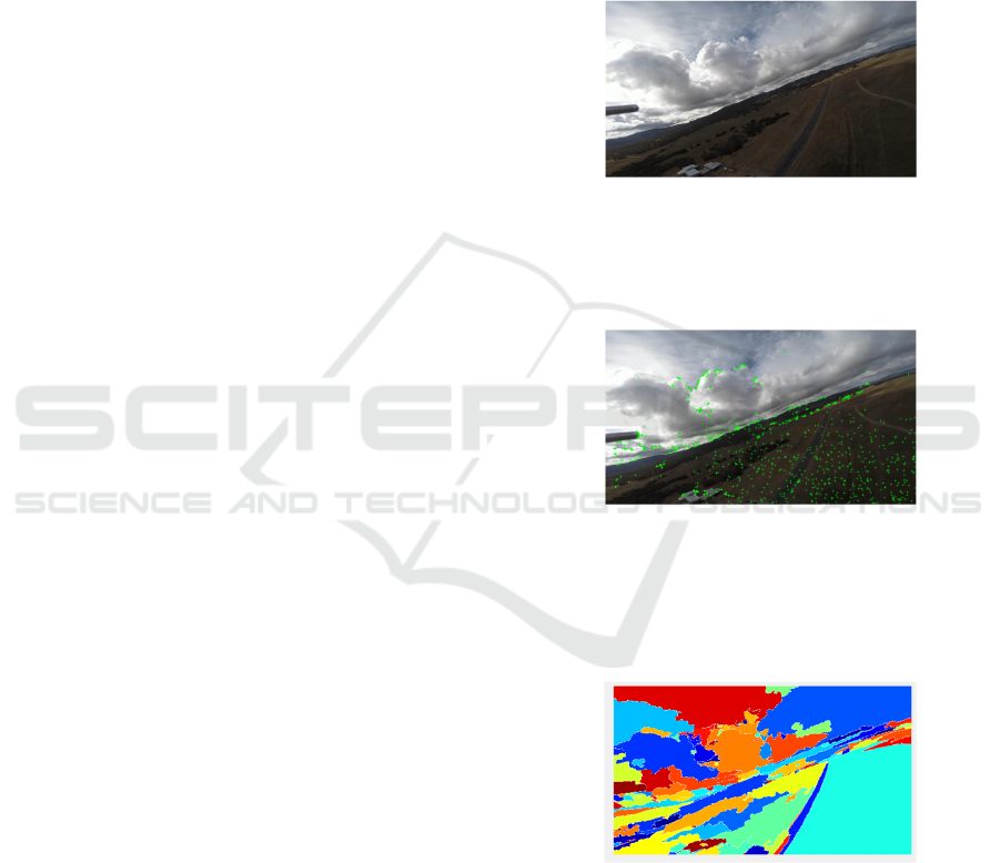
5 SIMULATION RESULTS
Map points marked on the image were obtained as
vSLAM output from the MATLAB simulation.
Subsequently, segmentation was applied to the last
read image, dividing it into regions. Utilizing the
segmented regions and current position information,
a bounding box was drawn around the designated
landing area. The outputs obtained are provided
below.
Figure 1: The original image.
The landmarks are printed on all the images, but
the final frame is the interested one at all. Because the
landing area is appeared thoroughly in the last frame.
Figure 2: The land marked image.
Here, the image is segmented into regions by
Watershed method. Each region is shown in a
different colour to discriminate the landing zone
easily.
Figure 3: The segmented image
After the image was segmented into regions, the
landing zone was determined. Then, to define the
landing zone, a bounding box is drawn to cover this
zone properly. The landmarks within the bounding
box boundaries were detected to help to controller to
track a reference trajectory.
ICINCO 2025 - 22nd International Conference on Informatics in Control, Automation and Robotics
232
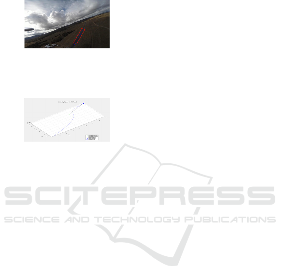
Figure 4: Bounding box representation.
Finally, according to the reference trajectory over
the landing zone, a start and end point are determined.
Then, the movement of the UAV on this trajectory is
controlled with MPC algorithm.
Figure 5: Trajectory tracking result of MPC.
6 CONCLUSION
This paper successfully demonstrates a robust vision-
based autonomous landing system for a fixed-wing
UAV that integrates a Linear Model Predictive
Control (MPC) strategy with Visual Simultaneous
Localization and Mapping (vSLAM). By leveraging
an SVD-based Kalman filter in the vSLAM
framework, we achieve improved accuracy and
numerical stability in map point updates and reduce
common issues such as noise accumulation and
computational errors. The image processing and
segmentation module using Watershed Transform
and incorporating real-time vSLAM location data
effectively identifies and defines the target landing
area, enabling precise placement of a bounding box.
This visual information is then seamlessly fed to the
linearized MPC controller, which dynamically tracks
a predefined landing trajectory. Simulation results
clearly demonstrate the system's ability to accurately
follow the desired path over the designated landing
zone and validate the effectiveness of our combined
vSLAM-MPC architecture for safe and autonomous
fixed-wing UAV landings.
REFERENCES
Amasyalı, M. F., Münük, A., & Salı, M. (2010). Kamera
görüntülerinden gidilen yolun kestirimi [Estimation of
the path traveled from camera images]. Dicle
Üniversitesi Mühendislik Fakültesi Mühendislik
Dergisi, 1(1), 5–11.
Andert, Franz, and Luis Mejias. “Improving Monocular
SLAM with Altimeter Hints for Fixed-Wing Aircraft
Navigation and Emergency Landing.” 2022
International Conference on Unmanned Aircraft
Systems (ICUAS), 1 June 2015,
Behera, L., Kamath, A. K., & Tripathi, V. K. (2020).
Vision-based autonomous control schemes for
quadrotor unmanned aerial vehicle.
Boij, J. N. (2022). Localization of Combat Aircraft at High
Altitude using Visual Odometry.
Camacho, Eduardo F, and Carlos Bordons. Model
Predictive Control. Advanced Textbooks in Control and
Signal Processing, 1 Jan. 1999.
Campoy, Pascual, et al. “Computer Vision Onboard UAVs
for Civilian Tasks.” Journal of Intelligent and Robotic
Systems, vol. 54, no. 1-3,7Aug.2008,pp.105–135,
https://doi.org/10.1007/s10846-008-9256-z.
García-Pulido, J.A., et al. “Recognition of a Landing
Platform for Unmanned Aerial Vehicles by Using
Computer Vision-Based Techniques.” Expert Systems
with Applications, vol. 76, June 2017, pp. 152–165,
https://doi.org/10.1016/j.eswa.2017.01.017.
Gautam, A., Sujit, P., & Saripalli, S. (2014). A survey of
autonomous landing techniques for UAVs. 2022
International Conference on Unmanned Aircraft
Systems(ICUAS), 1210–1218. https://doi.org/10.
1109/icuas.2014.6842377
Gavilan, F., Vazquez, R., & Esteban, S. (2015). Trajectory
tracking
for
fixed-wing
UAV
using
model
predictive control and adaptive backstepping. IFAC-
PapersOnLine,48(9),132–137.
Gavilan, Francisco, et al. “An Iterative Model Predictive
Control Algorithm for UAV Guidance.” IEEE
Transactions on Aerospace and Electronic Systems, vol.
51, no. 3, July 2015,pp.2406–2419,
Hang, Y., Zhang, T., & Huang, S. (2018, May).
Comparison of EKF based SLAM and optimization
based SLAM algorithms. Paper presented at the 13th
IEEE Conference on Industrial Electronics and
Applications (ICIEA), Wuhan,China.IEEE.
https://doi.org/10.1109/iciea.2018.8397911.
Kalay, Adnan, and İlkay Ulusoy. “Görüntü Tabanlı Eş
Zamanlı Lokalizasyon ve Harita Çıkarma: Stereo ve
Mono SLAM.” IEEE Sinyal İşleme ve İletişim
Uygulamaları Kurultayı, Kocaeli University, 2009.
Kaur, Dilpreet, and Yadwinder Kaur. “Various Image
SegmentationTechniques:AReview.”International
Journal of Computer Science and Mobile Computing,
vol.3, no.5,2014, pp.809–814.
Kazerouni, I. A., Fitzgerald, L., Dooly, G., & Toal, D. (2022).
A survey of state-of-the-art on visual SLAM. Expert
Systems With Applications, 205, 117734. https://doi.
org/10.1016/j.eswa.2022.117734
Kong, W., Zhou, D., Zhang, D., & Zhang, J. (2014,
October). Vision-based autonomous landing system for
unmanned aerial vehicle: A survey. Paper presented at
the 2014 International Conference on Multisensor
Fusion and Information Integration for Intelligent
Vision-Based Autonomous Landing for the MPC Controlled Fixed Wing UAV
233

Systems (MFI),Beijing,China,IEEE. https://doi.org/10.
1109/MFI.2014.6997750
Lemaire, Thomas, et al. “Vision-Based SLAM: Stereo and
Monocular Approaches.” International Journal of
Computer Vision, vol. 74, no. 3, 9 Feb. 2007, pp.343–
364.
Liu, et al. “An Onboard Vision-Based System for
Autonomous Landing of a Low-Cost Quadrotor on a
Novel Landing Pad.” Sensors, vol. 19, no. 21, 29 Oct.
2019, p.4703,
https://doi.org/10.3390/s19214703.
MathWorks. (n.d.). Optimization Problem. MATLAB &
Simulink, from https://www.mathworks.com/help/mpc/
ug/optimization- problem.html
MathWorks. (n.d.). What Is Model Predictive Control
from https://www.mathworks.com/help/mpc/gs/what-is-
mpc.html
MathWorks. (n.d.).Monocular Visual Simultaneous
Localization and Mapping. MATLAB & Simulink.
https://www.mathworks.com/help/vision/ug/mo
nocular-visual-simultaneous-localization-and-
mapping.html
Patruno, C., Nitti, M., Petitti, A., Stella, E., & D’Orazio, T.
(2018). A Vision-Based approach for unmanned aerial
vehicle landing. Journal of Intelligent &
RoboticSystems,95(2),645–664. https://doi.org/
10.1007/s10846-018-0933-2
Purdue University. (2021). UAV_Dataset home page.
https://engineering.purdue.edu/~bouman/UAV_
Dataset/
Rabah, M., Rohan, A., Talha, M., Nam, K., & Kim, S. H.
(2018). Autonomous vision-based target detection and
safe landing for UAV. International Journal of Control
Automation and Systems,16(6),3013–3025. https://doi.
org/10.1007/s12555-018-0017-x
Riccardo Giubilato, et al. A Comparison of Monocular and
Stereo Visual FastSLAM Implementations. 1 June
2016,pp.227–232, https://doi.org/10.1109/
metroaerospace.2016.75 73217..
Rondon, Eduardo, et al. “Vision-Based Altitude, Position
and Speed Regulation of a Quadrotor Rotorcraft.” 2011
IEEE/RSJ International Conference on Intelligent
Robots and Systems, 1Oct.2010,pp.628–633,
https://doi.org/10.1109/iros.2010.5652745.
Sun, Da-Wen. Computer Vision Technology for Food
Quality Evaluaton. Boston, Ma, Elsevier, 2017.
Unal, G. (2021). Visual target detection and tracking based
on Kalman filter. Journal of Aeronautics and Space
Technologies, 14(2), 251–259.
Urbanski, Konrad. “Control of the Quadcopter Position
Using Visual Feedback.” International Conference on
Mechatronics - Mechatronika, 1 Dec. 2018.
Vidal, V. F., Honório, L. M., Santos, M. F., Silva, M. F.,
Cerqueira, A. S., & Oliveira, E. J. (2017, May 1).
UAV vision aided positioning system for location and
landing. IEEEXplore.
https://doi.org/10.1109/CarpathianCC.2017.
797 0402
Wang, L., Libert, G., & Manneback, P. (1992, December).
Kalman filter algorithm based on singular value
decomposition. Paper presented at the 31st IEEE
Conference on Decision and Control, Tucson,
AZ,USA.IEEE.
Xin, L., Tang, Z., Gai, W., & Liu, H. (2022). Vision-Based
Autonomous Landing for the UAV: A Review.
Aerospace, 9
(11), 634.
Zhang, Yanhao, et al. “Comparison of EKF Based SLAM
and Optimization Based SLAM Algorithms.” OPUS -
Open Publications of UTS Scholars (University of
Technology Sydney), 1May2018.
ICINCO 2025 - 22nd International Conference on Informatics in Control, Automation and Robotics
234
