High-Precision Contour Tracking for Mobile Manipulators in Large-Scale
Industrial Applications
Buu Hai Dang Trinh
a
, Daniel Heß
b
and Christof R
¨
ohrig
c
IDiAL – Institute for the Digital Transformation of Application and Living Domains,
Dortmund University of Applied Sciences and Arts, Dortmund, Germany
Keywords:
Mobile Manipulator, Artificial Landmarks, Contour Tracking, Trajectory Control, High-Precision Localization.
Abstract:
Industrial manipulators are limited in their workspace due to mechanical constraints, which pose significant
challenges in large-scale industrial applications. Expanding a robot’s workspace often involves deploying
additional stationary manipulators or integrating linear axes, both of which increase installation costs and system
complexity without gaining much flexibility. A more effective and flexible solution is to integrate industrial
manipulators onto mobile platforms. To support this research, the authors developed a mobile manipulator
system consisting of a mobile platform driven by two Differential Drive Steering Units and an industrial
robotic arm with six Degrees of Freedom (DoF). This configuration provides the system with nine DoF in its
configuration space, substantially extending the workspace compared to conventional fixed-base manipulators.
A trajectory control method is proposed to ensure smooth, low-vibration, and high-precision motion during
operation. To enable accurate localization, a cost-effective method based on a 2D laser sensor and artificial
landmarks is introduced. Furthermore, a high-precision contour tracking algorithm is developed to monitor the
position of the end-effector relative to the workpiece. The proposed methods are validated through real-world
experiments, demonstrating millimeter-level accuracy in both positioning and tracking.
1 INTRODUCTION
Manipulators are widely used in manufacturing due to
their exceptional flexibility, precision, and efficiency.
Owing to their ability to seamlessly integrate with a
wide range of end-effectors, manipulators can be pro-
grammed to perform diverse tasks, including heavy,
hazardous, and dangerous operations that pose poten-
tial risks to human workers, thereby enhancing work-
place safety and reducing the likelihood of occupa-
tional accidents. Furthermore, they are capable of
maintaining high levels of precision and repeatability,
ensuring consistent product quality and reliability in
production lines with stringent tolerance requirements.
With the flexibility to be integrated into automated pro-
duction systems, combined with sensors and advanced
technologies, manipulators play a pivotal role in the ad-
vancement of smart manufacturing lines, thus promot-
ing comprehensive industrial automation in modern
industries.
Nevertheless, these manipulators are inherently
limited in their workspace as a result of mechani-
a
https://orcid.org/0009-0008-3661-3569
b
https://orcid.org/0000-0002-4627-8951
c
https://orcid.org/0000-0002-3286-3703
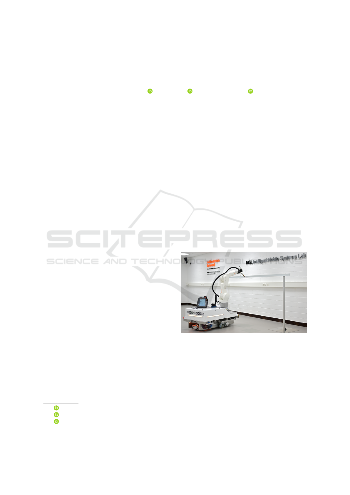
Figure 1: MobileRobot: Omnidirectional mobile platform
with a 6-DoF manipulator.
cal constraints such as joint configurations, structural
dimensions, and arm length. In applications involv-
ing the processing of large-scale components — such
as those encountered in shipbuilding, aerospace, and
wind turbine manufacturing — the required workspace
often exceeds the reach and flexibility of stationary ma-
nipulators.
A common approach to overcoming workspace
limitations is the strategic deployment of additional sta-
60
Trinh, B. H. D., Heß, D. and Röhrig, C.
High-Precision Contour Tracking for Mobile Manipulators in Large-Scale Industrial Applications.
DOI: 10.5220/0013709500003982
Paper published under CC license (CC BY-NC-ND 4.0)
In Proceedings of the 22nd International Conference on Informatics in Control, Automation and Robotics (ICINCO 2025) - Volume 2, pages 60-71
ISBN: 978-989-758-770-2; ISSN: 2184-2809
Proceedings Copyright © 2025 by SCITEPRESS – Science and Technology Publications, Lda.

tionary manipulators throughout the work area. How-
ever, this approach considerably increases installation
costs and system complexity, particularly with respect
to coordination and control. Another widely used so-
lution is the integration of linear axes — commonly
referred to as the seventh axis — onto which a single
manipulator is mounted and can traverse along a pre-
defined track. For example, systems like the KUKA
KL 1500 extend the working range of a robot with-
out requiring multiple manipulators (KUKA Robotics,
2025). However, this configuration only allows move-
ment along one axis and is not flexible when the
workspace or task changes. Adjusting the system usu-
ally requires extra mechanical work and reprogram-
ming. Mobile manipulators, which combine indus-
trial manipulators with autonomous mobile platforms,
are increasingly recognized as a promising solution
to overcome the inherent workspace limitations (Gh-
odsian et al., 2023). Nevertheless, the development
of such systems poses significant challenges, as it re-
quires maintaining high positioning accuracy and op-
erational efficiency while addressing the uncertainties
introduced by both the mobile base and the manipula-
tor (Sereinig et al., 2020).
Industrial mobile manipulators typically operate in
highly structured environments where object positions
are fixed and predetermined. This setup enables more
predictable, stable, and efficient navigation and opera-
tion. Unlike those used in service or domestic appli-
cations, they must meet strict accuracy requirements
— particularly at the end-effector — for tasks such
as gripping, welding, painting, and assembly (Gawel
et al., 2019). Since the end-effector’s pose results from
the combined kinematics of the mobile base and the
manipulator, any inaccuracy in the platform’s move-
ment can compromise overall task performance.
As part of this research, a mobile manipulator sys-
tem was designed combining a mobile platform driven
by two Differential Drive Steering Units (DDSUs)
and a 6-DoF industrial robotic arm (see Fig. 1). This
configuration enables the platform to achieve omnidi-
rectional movement while retaining the advantages of
conventional wheels. Compared to Mecanum wheels,
the DDSU-based platform significantly reduces vibra-
tions, thereby enhancing the system’s accuracy and
stability. We performed a measurement of the dis-
placement of the Tool Center Point (TCP) position
caused by vibrations generated by the platform dur-
ing the linear phase at 800 mm/s, as illustrated in
Fig. 2. The results demonstrate that the DDSU-based
platform generates significantly lower vibrations than
the Mecanum-wheeled platform, leading to improved
end-effector stability and positioning accuracy. Fur-
thermore, we have presented a system control model
to address the kinematic constraints of DDSUs. While
these units enable omnidirectional movement, they in-
troduce specific limitations that require careful control
to maintain accurate and efficient system performance
(Heß et al., 2023).
0
1
2
3
4
5
6
7
8
9
10
0 0.1 0.2 0.3 0.4 0.5 0.6 0.7 0.8 0.9 1
Offset (in mm)
Time (in seconds)
Mecanum Platform
DDSU Platform
Figure 2: Displacement of base and TCP positions during
linear motion.
The localization of mobile manipulators within the
workspace is essential for performing tasks accurately.
However, advanced localization systems based on
3D Light Detection and Ranging (LiDAR) sensor
or motion capture systems are often prohibitively
expensive and may not be feasible for many in-
dustrial environments. Radio-based localization
technologies, such as Ultra-Wideband (UWB), offer
high positioning accuracy and low latency, making
them an attractive alternative. Nevertheless, UWB
still encounters significant challenges in complex
industrial environments due to signal interference and
multipath propagation. The performance of UWB can
degrade considerably in enclosed areas with metallic
structures or dense machinery, where signal reflections
and obstructions are prevalent (Delamare et al., 2020).
The main contributions of this paper are as follows:
1.
A mobile manipulator system, integrating an indus-
trial six-DoF robotic arm with a mobile platform
driven by two DDSUs, has been developed to sig-
nificantly expand the workspace for large-scale
industrial applications.
2.
A trajectory control method for the mobile ma-
nipulator has been proposed that ensures smooth,
low-vibration coordinated motion while fully con-
sidering the kinematic and mechanical constraints
of the DDSU-driven platform.
3.
A cost-effective localization method based on a
2D laser sensor and artificial landmarks has been
introduced.
4.
A contour tracking algorithm has been devel-
High-Precision Contour Tracking for Mobile Manipulators in Large-Scale Industrial Applications
61

oped to achieve high-precision control of the end-
effector position relative to the workpiece during
the entire task execution.
5.
The proposed methods have been validated in real-
world scenarios, demonstrating that the mobile
manipulator system achieves millimeter-level posi-
tioning and tracking accuracy.
2 RELATED WORK
A variety of mobile manipulator systems have been
developed to overcome the workspace limitations of
stationary robots. Representative systems include
KUKA’s KMR iiwa and KMR QUANTEC, both of
which integrate omnidirectional platforms with KUKA
industrial arms. Another example is RB-KAIROS+, a
mobile manipulator from Robotnik Automation that
combines an omnidirectional base with the UR5e,
UR10e, or UR16e collaborative robotic arms. These
systems are designed for flexible industrial and intral-
ogistics applications. Additionally, researchers at the
Dortmund University of Applied Sciences and Arts
developed OmniMan, a mobile manipulator system for
human-robot collaboration in intralogistics (R
¨
ohrig
and Heß, 2020).
All of these systems use Mecanum-wheeled plat-
forms, which allow for omnidirectional movement in
narrow spaces. Mecanum wheels consist of driven
hubs combined with free-spinning rollers mounted at
an angle to the wheel axis, allowing the platform to
move in any direction. However, these rollers gener-
ate vibrations during motion, which can reduce the
system’s stability and accuracy and negatively affect
production quality (Bae and Kang, 2016).
Zhewen et al. proposed combining Mecanum
wheels with a dedicated suspension system to min-
imize vibrations and improve comfort (Zhewen et al.,
2024). In addition to Mecanum wheel-based designs,
omnidirectional platforms can be implemented using
steered standard wheels. An overview of such plat-
forms is provided (Jacobs, 2018). Wheel modules
enabling omnidirectional motion can be designed ei-
ther with active steering motors (Jacobs et al., 2012)
or using differential drive mechanisms (Jacobs and
Schaefer, 2020).
3 PROBLEM FORMULATION
In this paper, the problems of motion control, localiza-
tion, and contour tracking for a large-scale industrial
mobile manipulator system, designed specifically for
automated welding of large objects are addressed. The
system consists of a six DoF robotic arm mounted
on an omnidirectional mobile platform driven by two
DDSUs. The robotic arm enables full six DoF spatial
manipulation, allowing precise control of position and
orientation in three-dimensional space. In addition,
the omnidirectional platform provides planar mobil-
ity, enabling two-dimensional translation and rotation.
Consequently, the entire mobile manipulator system
exhibits a total of nine DoF in its configuration space.
Therefore, the mobile welding manipulator (MWM) is
an overdetermined system where the additional DoF
in configuration space can be used to optimize the mo-
tion of the MWM. The welding path is specified in
the three-dimensional Cartesian space of the MWM’s
operational workspace. To maintain weld quality, the
welding torch is required to track this path at predeter-
mined linear and angular velocities. Since the weld-
ing path may extend beyond the reachable workspace
of the robotic arm, it is necessary for the arm and
the mobile platform to coordinate their movements
synchronously. The forward kinematics of a mobile
manipulator can be generally formulated as:
p = f (q), with p =
x
y
z
α
β
γ
, and q =
q
p
q
a
. (1)
Where
p
denotes the pose of the mobile manip-
ulator’s tool frame with respect to the world frame,
such that
p ∈ R
3
× SO(3)
. The vector q represents
the generalized coordinates in the configuration space
(C-space), consisting of the 2D pose of the mobile
platform, defined as
q
p
= (x
p
,y
p
,θ
p
)
T
, where
q
p
∈
R
2
× S
1
, and the joint angles of the manipulator arm,
given by
q
a
= (θ
1
,...,θ
6
)
T
. The inverse kinematics,
crucial for trajectory planning and control, can thus be
expressed as:
q = f
−1
(p) (2)
The inverse kinematics problem of the system is
overdetermined because it has more degrees of free-
dom than required to define the end-effector pose.
This leads to multiple possible joint configurations
for the same task, which can be resolved using numer-
ical methods to optimize motion in the configuration
space. In addition, the system’s redundancy not only
improves motion efficiency and safety but also extends
the manipulator’s reachable workspace beyond the
physical limitations of the arm alone.
The omnidirectional mobile platform, driven by
two DDSUs, can simultaneously translate along the
x
- and
y
-axes and rotate about the
z
-axis, thereby pro-
viding full mobility in the 2D plane. The world frame
ICINCO 2025 - 22nd International Conference on Informatics in Control, Automation and Robotics
62
F
W
is a fixed reference frame used to describe the task
space. The MWM operates within this workspace,
and its motion is expressed relative to
F
W
. The robot
frame
F
R
is a coordinate frame that is rigidly attached
to the mobile platform, with its origin located at the
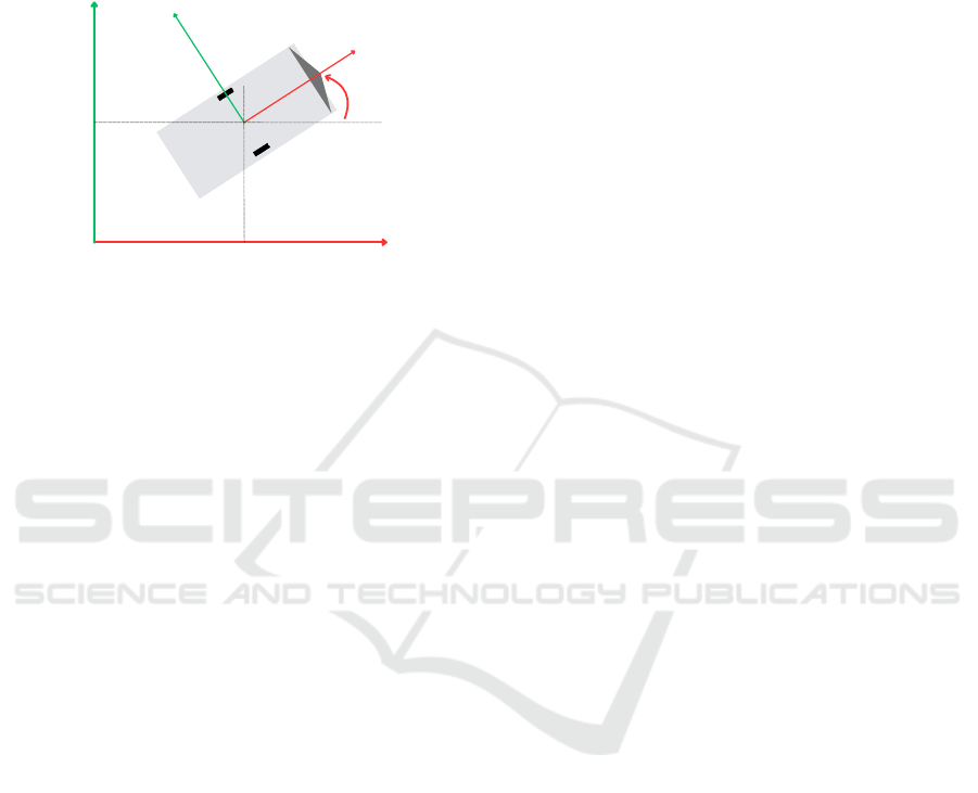
geometric center of the platform (see Fig. 3).
y
W
x
W
y
R
x
R
y
P
x
P
P
θ
Figure 3: Pose definition of the mobile manipulator in the
world p
p
and robot frame F
R
.
The pose of the mobile platform relative to the
world frame is defined as
p
p
= (x
p
,y
p
,θ
p
)
T
, where
x
p
and
y
p
represent the position in the 2D plane, and
θ
p
is
the heading angle around the orthogonal
z
-axis. This
coordinate setup allows for a clear separation between
global task planning in the world frame and local con-
trol actions in the robot frame. The platform’s pose
p
p
serves as a critical reference for defining its veloc-
ity, localization, and control inputs within the world
frame. However, for control implementation, these
quantities are generally transformed and expressed in
the robot frame
F
R
, where they are more convenient
and consistent to manage in motion control schemes.
The transformation of velocities from the robot frame
to the world frame is performed using the platform’s
heading angle (θ = θ
p
):
˙p
R
= R(z,θ) ˙p
W
, ⇒ ˙p
W
= R
−1
(z,θ) ˙p
R
,
with ˙p
W
=
˙x
W
˙y
W
˙
θ
, ˙p
R
=
˙x
R
˙y
R
˙
θ
,
and R(z, θ) =
cosθ −sinθ 0
sinθ cosθ 0
0 0 1
(3)
To determine the necessary wheel velocities and steer-
ing angles that enable the platform to achieve a desired
motion in the robot frame, the inverse kinematics of the
platform is formulated as a set of nonlinear equations:
˙φ
β
= f
p
( ˙p
R
), (4)
where
• ˙p
R
= ( ˙x
R
, ˙y
R
,
˙
θ)
T
is the velocity of the platform
over the ground described in the robot frame.
• ˙φ = (
˙
ϕ
1
,
˙
ϕ
2
,...,
˙
ϕ
n
)
T
is the vector of wheel angu-
lar velocities.
• β = (β
1
,β
2
,...,β
m
)
T
is the vector of wheel steer-
ing angles.
The forward kinematics can be obtained by using
a nonlinear least-squares approach
˙p
R
= f
−1
p
˙φ
β
, (5)
In contrast to the overdeterminacy in the mobile
manipulator, the over-actuated drive structure of the
platform cannot be used to achieve additional degrees
of freedom in C-space. The overdeterminacy of the
platform is subject to motion constraints, which must
be satisfied to avoid additional wheel slip.
The global localization of the MWM is performed
using a 2D LiDAR sensor combined with strategically
placed artificial landmarks around the workspace of
the MWM. A localization algorithm processes the Li-
DAR and landmark data to estimate the pose of the
platform relative to the world coordinate frame
p
p
.
The localization algorithm processes the LiDAR mea-
surements and the known locations of these landmarks
to estimate the platform’s pose relative to the world
coordinate frame F
W
.
Although the localization system achieves an ac-
curacy of a few centimeters, this level of precision
remains insufficient to meet the stringent requirements
of industrial applications. Furthermore, the global
localization system is affected by environmental inter-
ference, landmark occlusions, and the limited scanning
range of the LiDAR, leading to reduced stability dur-
ing operation. For the welding task, high-precision
contour tracking of the target workpiece is required to
ensure accurate torch positioning along the welding
path. Since the global localization system alone cannot
guarantee the required accuracy at the end-effector, a
2D profile scanner is mounted at the end-effector to
support local contour tracking. This sensor does not di-
rectly provide contour information, but instead returns
profile data as a set of distance measurements captured
along the scanning line. Therefore, additional data
processing is necessary to reconstruct and accurately
estimate the object’s contour.
By combining global localization with contour
tracking, the system is capable of performing high-
precision manipulation tasks with enhanced accuracy
and operational stability.
High-Precision Contour Tracking for Mobile Manipulators in Large-Scale Industrial Applications
63
4 PROPOSED LOCALIZATION
METHOD
4.1 Overview and Requirements
Accurate localization of the mobile platform is a fun-
damental prerequisite for performing high-precision
manipulation tasks in large-scale industrial applica-
tions. In structured and static environments, Adaptive
Monte Carlo Localization (AMCL) offers an efficient
and cost-effective solution for mobile platform local-
ization. However, its accuracy remains limited, with
position errors often reaching several tens of centime-
ters. Although the integration of QR codes on the
floor improves localization accuracy, it still fails to
meet the stringent requirements of industrial applica-
tions. This limitation becomes even more critical in
large and dynamic environments, where noise, mov-
ing obstacles, and changes in the environment further
degrade accuracy (Wang et al., 2021).
For contour tracking applications such as welding,
the system requires centimeter-level localization accu-
racy of the mobile base to ensure stable and precise
end-effector control. Improved base accuracy mini-
mizes the need for manipulator compensation, thereby
enhancing the stability and quality of the weld path.
4.2 Localization Architecture
In this project, the NAV245 2D LiDAR sensor (SICK
AG, Germany) is employed for environmental percep-
tion and distance measurement. The sensor covers
a
270
◦
scanning field with an angular resolution of
0.001
◦
for reflectors and
0.25
◦
for raw contour data.
Operating at 25 Hz, the sensor completes a full scan
in 40 ms and supports a maximum detection range of
50 m, depending on the target’s properties. According
to the manufacturer, for reflector-based data, the typi-
cal systematic measurement error is
±
10 mm, while
the statistical error is 8 mm (SICK AG, 2022). These
features enable precise and low-latency positioning of
the robot in large indoor environments using only a
single sensor.
Artificial landmarks are constructed using RA3-
class microprismatic retroreflective foil, which enables
incident laser beams to be returned directly to the sen-
sor regardless of the angle of incidence. This full-cube
microprism technology achieves remission values of
up to 3,000%, which is considerably higher than the
maximum 100% remission of natural surfaces. As
a result, measurements on reflectors provide higher
precision and signal stability, making them ideal for
landmark-based localization in indoor environments.
The odometry system is derived from the DDSU
developed by G
¨
otting KG. Each DDSU integrates a
pseudo-incremental encoder providing 65,535 pulses
per revolution for wheel rotation measurement of
the foure active wheels of both DDSUs, and a steer-
ing angle encoder with 4,096 pulses per revolution
for accurate steering position feedback. These high-
resolution sensors provide precise relative motion es-
timation of the mobile platform. However, while the
high-resolution encoders ensure low-noise and high-
frequency odometry data, the odometry data tends to
accumulate errors over time due to wheel slip and in-
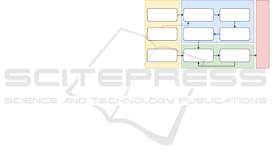
tegration drift. Fig. 4 illustrates the overall pipeline
of the proposed high-precision and robust localization
system.
LiDAR Data
(Distance & Intensitty)
Landmark Map
Wheel Odometry Data
(Local Frame)
Landmark Detection &
Identification
GDOP Calcutation &
Trilateration
Coordinate
Transformation
Platform Pose Estimation
(Global frame)
EKF-Based Fusion
(Prediction & Correction)
Estimated Platform Pose
(Global frame)
Perception Pose Estimation
Sensor Fusion & Correction
Platform
Control
Figure 4: Overview of the proposed localization architecture.
The Perception module is responsible for contin-
uously collecting distance and intensity information
from a 2D LiDAR scanner as well as odometry data
from wheel encoders. The Pose Estimation module
utilizes LiDAR data in combination with a previously
generated landmark map containing known global po-
sitions of all landmarks in the workspace. This enables
the system to accurately detect and identify the land-
marks present in the current scan. Once the landmarks
are identified, the module calculates the Geometric Di-
lution of Precision (GDOP) to evaluate how the spatial
configuration of the landmarks relative to the sensor
affects the accuracy of the position estimation. The
GDOP metric guides the selection of the most suitable
landmark-set for trilateration, ensuring improved esti-
mation reliability. The trilateration method is used to
estimate the global position of the scanner. Finally, by
applying a coordinate transformation, the global pose
of the mobile platform is determined.
Trilateration can achieve high positioning accuracy
when landmarks are correctly identified and the dis-
tance measurements are sufficiently reliable. However,
in practice, these measurements are often affected by
noise and environmental conditions. Due to its sen-
sitivity, even small errors can result in significant de-
viations in position estimation. To improve localiza-
ICINCO 2025 - 22nd International Conference on Informatics in Control, Automation and Robotics
64
tion accuracy and robustness, an Extended Kalman
Filter (EKF) is employed to fuse the landmark-based
position estimates with the robot’s internal odometry.
Through this process, the system effectively compen-
sates for odometry drift and minimizes the impact of
environmental noise on LiDAR-based measurements,
ensuring consistent pose estimation over time. Finally,
the global pose generated by the Sensor Fusion & Cor-
rection module is transmitted to the system controller
for platform control.
4.3 Localization Algorithm
To ensure the availability of a sufficient number of
reference landmarks for position estimation, a total of
12 artificial landmarks were mounted on the laboratory
walls (see Fig. 5). The positions of these landmarks
were determined by combining measurements from a
Vicon motion tracking system and the NAV245 LiDAR
scanner, which significantly reduced errors compared
to manual measurement methods. The landmarks were
strategically arranged in distinct pairs, ensuring that
the distance within each pair was unique.
Artificial landmarks
Figure 5: Landmark setup for the experimental environment.
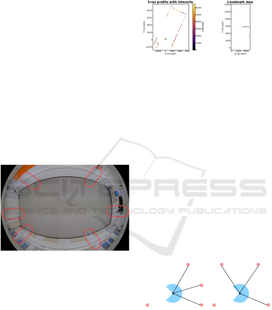
In each scan cycle, the LiDAR sensor generates a
scan profile representing the relative positions of all
points detected within its field of view (see Fig. 6a).
The artificial landmarks are characterized by signifi-
cantly higher reflection intensity compared to natural
surfaces. By applying a predefined intensity threshold,
the system is able to distinguish the artificial landmarks
from other objects. Once detected, these landmarks
are matched against the stored landmark map (see
Fig. 6b) to determine their identities. As a result of
this process, each successfully identified landmark is
associated with both its relative position with respect
to the LiDAR sensor and its global position within the
workspace.
The global position of the LiDAR scanner is es-
timated using the Trilateration method. This method
(a) LiDAR scan profile
(b) Reference landmark map
Figure 6: Required data for the Pose Estimation Module.
utilizes the measured distances between the scanner
and three previously identified artificial landmarks, lo-
cated at
M = (x
m
,y
m
)
,
N = (x
n
,y
n
)
, and
K = (x
k
,y
k
)
.
The distances to these landmarks, denoted as
r
m
,
r
n
,
and
r
k
, are measured by the LiDAR scanner. The scan-
ner’s position
(x,y)
is then determined by solving the
following system of nonlinear equations:
(x − x
m
)
2
+ (y − y
m
)
2
= r
2
m
(x − x
n
)
2
+ (y − y
n
)
2
= r
2
n
(x − x
k
)
2
+ (y − y
k
)
2
= r
2
k
(6)
The accuracy of position estimation using the Tri-
lateration method depends on the geometric arrange-
ment of the landmarks relative to the LiDAR sensor.
In cases where the landmarks have an unfavorable
geometric configuration (see Fig. 7a)—such as when
the reference landmarks are closely spaced or aligned
along a straight line—even small errors in distance
measurements can result in significant position es-
timation errors (Li et al., 2020). Therefore, to im-
prove estimation accuracy and minimize the influence
of measurement noise, only landmark combinations
with an optimal geometric configuration (see Fig. 7b)—
characterized by a low GDOP—are selected for the
Trilateration process.
Landmark
(a) High GDOP
Landmark
(b) Low GDOP
Figure 7: Relationship between the arrangement of the land-
marks and the GDOP value.
The GDOP is calculated using the observation ma-
trix
A
, which contains the direction vectors from the
LiDAR sensor to the landmarks, according to the fol-
High-Precision Contour Tracking for Mobile Manipulators in Large-Scale Industrial Applications
65

lowing equation:
GDOP =
r
trace
(A
T
A)
−1
,
with A =
x − x
1
r
1
y − y
1
r
1
... ...
x − x
n
r
n
y − y
n
r
n
,
and r
i
=
q
(x − x
i
)
2
+ (y − y
i
)
2
(7)
The global orientation of the LiDAR is calculated
using the atan2 function based on the relative posi-
tions of the detected landmarks and the LiDAR’s es-
timated position. By applying geometric coordinate
transformation to the global pose of the LiDAR, the
global pose of the mobile platform can be accurately
estimated. This pose is then used as an input for the
Sensor Fusion & Correction module, where it will be
fused with odometry data using the EKF to enhance
the accuracy and robustness of the position estimation.
For the implementation of the EKF, the state vector is
defined as:
x
t
= (x
W
t
,y
W
t
,θ
W
t
)
T
= f (x
t−1
,u
t
,w
t
), (8)
where u
t
is the control input vector at time
t
, repre-
senting the measured relative motion of the mobile
platform in its local coordinate frame, obtained from
odometry data. The process noise w
t
models uncer-
tainties in the motion model and is assumed to follow
a zero-mean Gaussian distribution to account for er-
rors such as wheel slip and odometry drift. In the
prediction step, the state is propagated based on the
control input, and the covariance is updated to reflect
the uncertainty:
ˆ
x
t|t−1
= f
ˆ
x
t−1|t−1
,u
t
,0
(9)
P
t|t−1
= A
t
P
t−1|t−1
A
T
t
+ W
t
Q
t
W
T
t
(10)
where
P
t|t−1
is the predicted state covariance matrix,
representing the uncertainty of the state after the pre-
diction step. A
t
and W
t
are the Jacobians of the motion
model with respect to the state and the process noise,
respectively. Q
t
is the process noise covariance ma-
trix, representing the uncertainties introduced by the
system dynamics and odometry errors.
The correction step is triggered immediately after
the global pose of the mobile platform is calculated
from the LiDAR measurements. It is performed using
the following set of equations:
˜
y
t
= z
t
− h
ˆ
x
t|t−1
,0
(11)
ˆ
x
t|t
=
ˆ
x
t|t−1
+ k
t
K
t
˜
y
t
(12)
K
t
= P
t|t−1
H
T
t
H
t
P
t|t−1
H
T
t
+ V
t
R
t
V
T
t
−1
(13)
P
t|t
= (I − K
t
H
t
)P
t|t−1
(14)
Here, the measurement function
h
ˆ
x
t|t−1
,0
maps the
predicted state into the measurement space. The resid-
ual
˜
y
t
is calculated as the difference between the actual
measurement
z
t
and the predicted measurement. The
Kalman gain
K
t
is computed to balance the uncer-
tainties between the predicted state and the measure-
ment, considering the measurement noise covariance
R
t
. The updated state estimate
ˆ
x
t|t
represents the cor-
rected global pose of the mobile platform at time
t
,
combining the prediction from odometry with the cor-
rection from the LiDAR measurements.
5 TRAJECTORY CONTROL AND
CONTOUR TRACKING
5.1 Contour Tracking Algorithm
Based on the pre-defined plan, the motion controller
of the mobile manipulator guides the TCP along the
processing trajectory. However, factors such as wheel
slippage, uneven terrain, joint backlash, and structural
flex can lead to deviations between the planned and
actual trajectory of the TCP. To ensure precise task
execution, an algorithm is required to accurately de-
tect these deviations. A 2D laser profile scanner is
mounted on the same end-effector as the welding torch
to capture the contour profile near the tool. It is ori-
ented such that the scanning area is angled forward in
the direction of motion, allowing it to detect the profile
of the area just ahead of the tool path (see Fig. 8a). In
T-joint welding applications, the weld seam is located
at the intersection of the vertical and horizontal plates.
To accurately identify the seam, the laser scanner must
have a field of view that includes parts of both surfaces
(see Fig. 8b).
Movement direction
Laser scanner
Tool
Contour
z
E
z
y
x
E
(a) Frontal view
d
act,h
d
act,v
Movement direction
Laser scanner
Tool
Contour
y
E
z
E
z
x
(b) Lateral view
Figure 8: Tool and Sensor Arrangement for Contour Track-
ing.
During each scan cycle, the laser profile scanner
captures a two-dimensional depth profile of the target
surface. Each profile consists of a sequence of dis-
crete data points, with each point containing three key
ICINCO 2025 - 22nd International Conference on Informatics in Control, Automation and Robotics
66
values: the x-coordinate, representing the horizontal
position along the scan line; the z-coordinate, indicat-
ing the measured height relative to the scanner; and
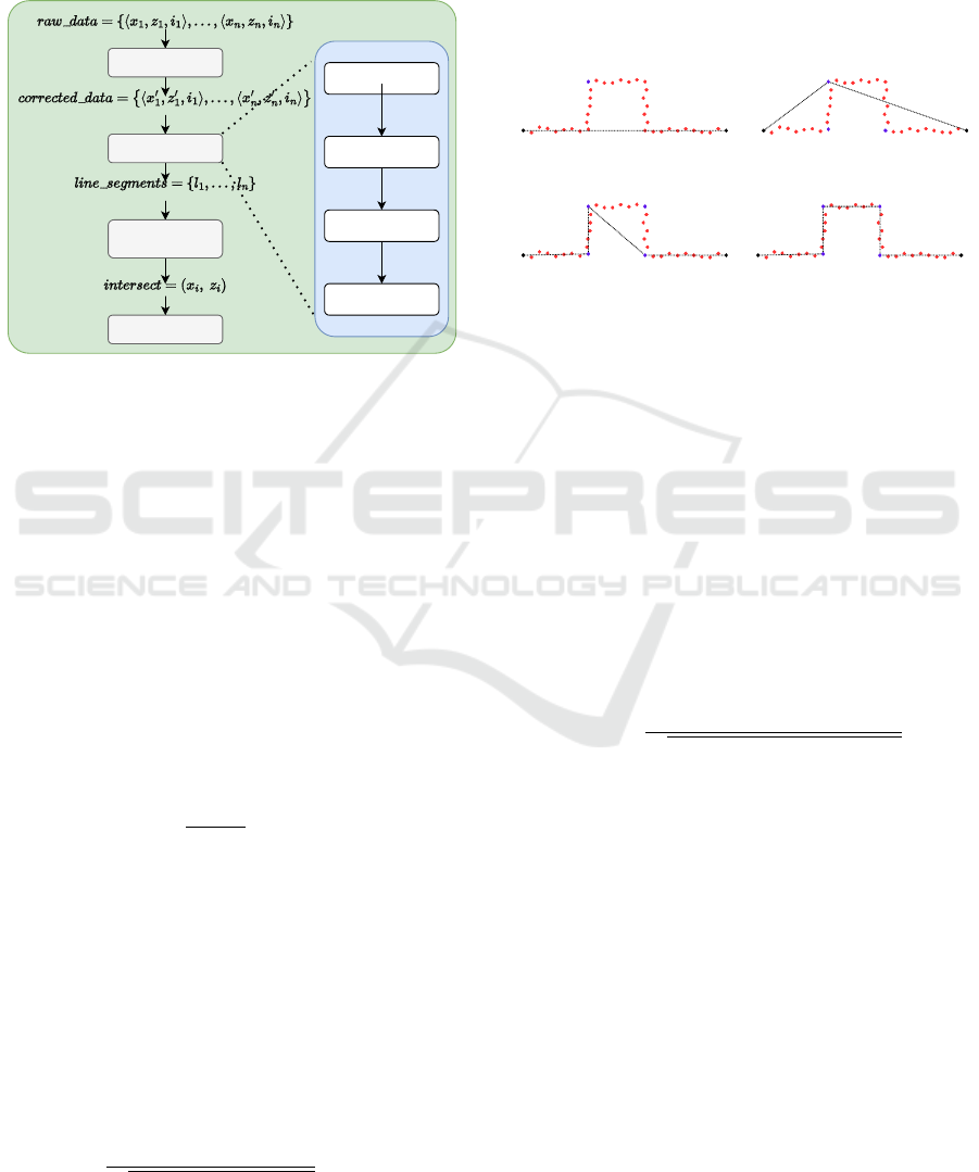
the intensity. The overall workflow of the system for
detecting the machining point and adjusting the trajec-
tory, based on laser profile data, is illustrated in Fig. 9.
Preprocessing
Line Extraction
Line Filtering
& Intersection
Tool path
adjustment
Detect
Breakpoints
Line
Estimation
Check
Fit
Linear
Regression
Figure 9: Workflow for welding position detection and tra-
jectory adjustment using laser profile data.
Before any computation is performed, the raw laser
profile data must be preprocessed. Irrelevant or unreli-
able points—typically characterized by low intensity
values—are removed. This helps reduce noise and
ensures that only meaningful surface features are used
in the next steps. To reduce measurement noise in
the distance measurements, a simple linear smoothing
filter is applied. This filter gives the current value
d
i
the highest weight, while still considering the adjacent
values to reduce local noise. The stability of break-
point detection and line fitting is improved through this
filtering approach. Such filtering enhances the quality
of breakpoint detection and the fitting of line segments
that follow.
d
′
i
= 0.2d
i−1
+ 0.6d
i
+ 0.2d
i+1
,
with d
i
=
q
z
2
i
+ x
2
i
(15)
The lines are extracted using the Split-and-Merge
algorithm. This algorithm provides a recursive ap-
proach for segmenting point data into linear compo-
nents. In the first step, a line
l
is drawn between the
first and last points of the currently considered set of
points. Next, all points between the current start and
end points are evaluated, and the orthogonal distance
from each point d
i
l
to l is computed.
d
i
l
=⃗v ·
x
i
− x
s
z
i
− z
s
,
with ⃗v =
1
p
(z
s
− z
e
)
2
+ (x
s
− x
e
)
2
z
e
− z
s
x
s
− x
e
(16)
If the maximum distance exceeds a predefined
threshold, the corresponding point is classified as an
outlier with respect to the current line segment
l
. The
point set is then split at this location, and the algo-
rithm is recursively applied to the resulting subsets.
The recursion terminates once all points in a segment
lie within the threshold distance from their respective
fitted line. As shown in Figure 10, the black lines are
fitted to the red points.
l
(x , z )
s s
(x , z )
e e
1.Split
(a)
1. Split
2. Split 2. Split
(b)
1. Split
2. Split 2. Split
3. Split
(c)
1. Split 3. Split
2. Split 2. Split
(d)
Figure 10: Stepwise representation of the operation of the
recursive line extraction method.
Breakpoint analysis allows the segmentation of
laser profile data into geometrically consistent sections,
such as areas where the surface changes direction or
curvature. Performing this analysis before applying
the recursive splitting process helps reduce unneces-
sary iterations and improves the overall efficiency of
line extraction. In this paper, the Bearing Angle (BA)
method (Harati and Siegwart, 2007) is used to detect
geometric discontinuities. This approach computes a
bearing angle value at each scan point based on consec-
utive distance measurements and the scanner’s angular
resolution α. This bearing angle is defined as:
BA
i
=
d
′
i
− d
′
i−1
cos(α)
q
d
′2
i
+ d
′2
i−1
− 2d
′
i
d
′
i−1
cos(α)
(17)
A breakpoint is detected at point
i
if the absolute dif-
ference between two consecutive BA values exceeds a
predefined threshold:
|
BA
i
− BA
i−1
|
≥ θ
threshold
(18)
The result of the split phase is a set of data subsets,
where each subset is assumed to be well approximated
by an individual straight line. However, to avoid over-
fitting—that is, generating too many segments due to
excessive sensitivity to small noise—additional valid-
ity checks are required. These include, for example,
verifying whether each segment contains a sufficient
number of points.
After the data has been segmented through the split
phase, each subset is processed independently to es-
timate the best-fitting straight line. This is done by
High-Precision Contour Tracking for Mobile Manipulators in Large-Scale Industrial Applications
67

applying linear regression to the points within each
segment (Arras and Tomatis, 1999). The resulting
line is then reformulated in Hesse normal form, which
is particularly useful for subsequent geometric opera-
tions. The Hesse parameters are computed using the
following equations:
α = atan2
−
1
2
·
∑
N
i=1
(¯z − z
i
)( ¯x − x
i
)
∑
N
i=1
(¯z − z
i
)
2
( ¯x − x
i
)
2
(19)
p = ¯x · cos(α) + ¯z · sin(α) (20)
Here,
¯x
and
¯z
denote the mean values of the co-
ordinates of the respective point set. The computed
line minimizes the orthogonal distance to the input
points, providing a robust and consistent representa-
tion for downstream processing, such as computing
the intersection between two adjacent line segments.
Once the intersection of two neighboring fitted lines is
determined, it is used as a control point to update the
trajectory of the welding tool.
5.2
Trajectory Tracking Control Scheme
The proposed control scheme for trajectory tracking
of the MWM is illustrated in Fig. 11. Based on the
Cartesian weld path, the motion planner computes
the complete trajectory
q(t) = (q
p
(t),q
a
(t))
T
in the
configuration space. The motion interpolator computes
the current state and its derivatives for each time step
in t to ensure smooth and continuous motion.
The platform’s motion controller is based on our
previously proposed control scheme for Mecanum-
driven omnidirectional platforms (R
¨
ohrig et al., 2017).
The underlying kinematic model of the MWM is also
adopted from our earlier work on redundant mobile
manipulators, as presented in (Heß et al., 2023). The
platform control consists of pose control, platform
kinematics, odometry, localization, and DDSU con-
trol. The platform kinematics are derived from the
platform’s motion model. The DDSU controller con-
trols the steering angle
β
i
and the velocity
v
i
for both
DDSUs based on differential drive kinematics using
the angular velocities
˙φ
of the four driven wheels.
Odometry is computed using the wheel encoder values
φ
and the measured passive steering angles
β
. Local-
ization is performed by fusing the odometry with data
from a SICK NAV245 LiDAR.
The tracking of the weld path is done by a laser
sensor that measures the deviation from the weld path.
Since the robotic arm is much more precise and dy-
namic than the robotic platform, the tracking control
uses the arm to control the deviation from the weld
path. The deviation is measured in the end-effector
coordinate frame, hence the end-effector Jacobian
J
E
a
(q
a
) =
∂f(q)
∂q
=
R
E
0
0
3×3
p
3×3
R
E
p
J
p
a
(q
a
) ˙q
a
(21)
is used to control the deviation. The tracking control
scheme is based on the well known Resolved-Rate
Motion Control (see (Corke, 2023)). When the arm
correction
∆q
becomes large, the motion planner cal-
culates a new trajectory to correct the platform’s pose
and reduce ∆q.
6 EXPERIMENTAL EVALUATION
To validate the proposed algorithm, two experiments
were conducted: one assessing the accuracy of the mo-
bile platform, and the other evaluating contour tracking
in a welding task.
6.1 Experimental Setup
The MWM used for the experiments described here
comprises a platform equipped with two DDSUs and
a KUKA KR 6 R900-2 robotic arm, controlled via a
KRC5 controller. An embedded PC running a real-
time Linux operating system that connects the mo-
bile platform’s DDSUs via Controller Area Network
(CAN) bus and the manipulator’s KRC5 controller
via real-time Ethernet. Serving as a centralized real-
time control system, the system controller PC synchro-
nizes the setpoints of all components in real time to
ensure coordinated operation. Every 200 ms, the SICK
NAV245 LiDAR provides a full
270
◦
scan, which is
used by the platform controller as feedback for the
pose control loop (see Fig. 11). The scanCONTROL
3012-100 laser profile sensor, mounted on the same
end-effector as the welding torch, is used in Trajectory
Tracking to enable closed-loop control of the robotic
arm. In the experimental setup, the T-joint is simu-
lated using an L-shaped profile instead of two separate
workpieces (see Fig. 12). For ground truth compari-
son, the MWM’s global pose is obtained via a Vicon
motion capture system, which offers high-precision
6-DoF tracking.
6.2 Experimental Results
In order to evaluate the effectiveness of the proposed
localization method, we applied a series of algorithms
to the dataset obtained from the NAV245 laser scanner.
The localization accuracy improved progressively with
each enhancement in the algorithmic pipeline. Trilater-
ation served only as the baseline, producing the largest
ICINCO 2025 - 22nd International Conference on Informatics in Control, Automation and Robotics
68
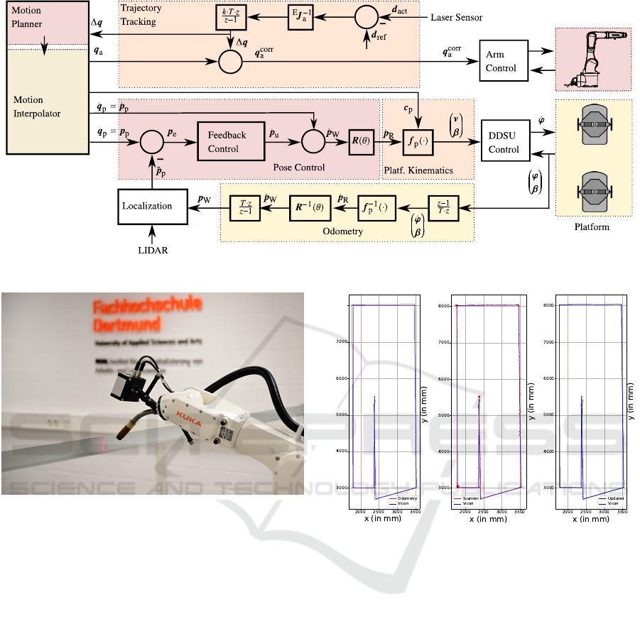
Figure 11: Block diagram for tracking a welding path with MWM.
Figure 12: Simulation of T-Joint weld using L-Profile.
variance in position estimates. Incorporating the opti-
mal geometric configuration of the detected landmarks
— based on GDOP analysis — significantly reduced
the standard deviation, minimized measurement noise,
and produced position estimates that were more stable
and more tightly clustered around the true location.
Next, the MWM was driven along a predefined
trajectory. During this motion, both odometry data and
scan measurements were recorded. Figure 13 show the
estimated trajectory using (a) raw odometry data, (b)
trilateration with GDOP, and (c) sensor fusion com-
bining odometry with trilateration + GDOP using an
Extended Kalman Filter. Each method was compared
against ground-truth data obtained from a Vicon mo-
tion capture system.
Due to wheel slippage and integration drift, the
trajectory estimated from odometry diverges signifi-
cantly from the ground truth. By contrast, trilateration
enhanced with GDOP filtering yields a trajectory that
more closely aligns with the actual path. However,
residual noise remains—particularly in turning seg-
8000
(a) Using odometry
data.
(b) Using Trilatera-
tion + GDOP.
(c) Trilateration +
GDOP + EKF.
Figure 13: Comparison of estimated trajectories using differ-
ent methods.
ments or in areas with limited landmark coverage—
likely due to suboptimal geometric configurations for
trilateration. The EKF-based data fusion method effec-
tively mitigates these errors, significantly enhancing
the accuracy and stability of mobile platform localiza-
tion.
To demonstrate the effectiveness of the EKF-based
localization approach, Figure 14 presents the absolute
differences between the estimated and ground-truth
values over time. The odometry-only method resulted
in Root Mean Square Errors (RMSE) of 24.32 mm
(
x
), 24.23 mm (
y
), and 0.01299 rad (
θ
). In contrast,
the EKF-based fusion significantly reduced these er-
rors, achieving RMSEs of 8.15 mm (
x
), 8.77 mm (
y
),
and 0.00497 rad (
θ
). These results highlight the ro-
bustness and precision of the proposed fusion method
High-Precision Contour Tracking for Mobile Manipulators in Large-Scale Industrial Applications
69
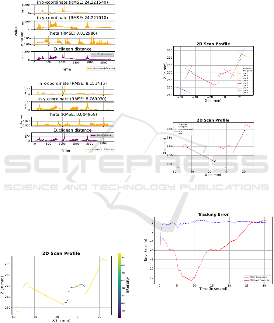
in dynamic operating scenarios. However, for pre-
cise end-effector control during welding, local contour
tracking is required.
(a) Using Odometry
Value
(b) Using EKF
Figure 14: Absolute error between estimated and ground-
truth values.
Contour tracking aims to accurately detect the ma-
chining point, which, in the context of simulated T-
joint welding, refers to the intersection line between
two metal plates. Maintaining precise and continuous
alignment between the welding torch and this intersec-
tion line is a critical factor that determines the quality
and stability of the weld. Figure 15 illustrates a typi-
cal depth and intensity profile acquired from the 2D
profile laser.
Figure 15: Depth and Intensity Profile from 2D Laser Scan.
The raw scan profile is processed to extract line
segments using the proposed contour tracking algo-
rithms, as shown in Figure 16a. In the final step, the
intersection of relevant line segments is computed to
determine the precise machining point, as shown in
Figure 16b. This intersection point is then used to
regulate the relative position between the laser sensor
and the workpiece. Since both the torch and the sensor
are mounted on the same end-effector, this adjustment
also determines the relative position between the torch
and the workpiece.
(a) Breakpoint detection and line segmen-
tation
(b) Intersection point estimation
Figure 16: Estimation of the precise machining point through
line extraction and intersection of 2D scan profile data.
Figure 17: Tracking error over time.
Figure 17 illustrates the deviation of the torch from
the welding path during motion. While the MWM
moves along the workpiece, the mobile platform main-
tains global localization using LiDAR, and the robotic
arm compensates for any deviations from the prede-
fined weld path. The blue curve represents the tracking
error with active contour tracking using laser sensor
ICINCO 2025 - 22nd International Conference on Informatics in Control, Automation and Robotics
70

feedback, whereas the red curve shows the error with-
out such feedback control. The tracking system ef-
fectively corrects deviations of the platform, which
reach up to 12 mm in this experiment. The blue curve
shows that the deviation does not exceed 2 mm when
the tracking controller is used.
7 CONCLUSION
In this paper, we presented a MWM designed for high-
precision contour tracking in large-scale industrial en-
vironments. The proposed system combines a 6-DoF
robotic arm suitable for welding tasks with an omnidi-
rectional mobile platform driven by DDSUs, allowing
for smooth and stable motion with reduced vibration.
The DDSUs contain kinematic constraints that must
be considered in motion planning and control. Each
unit has a limited steering angle and can be driven
in two different configurations by changing the direc-
tion of the wheel speeds. The entire weld trajectory
is planned in Cartesian space, with explicit consid-
eration of the motion constraints introduced by the
DDSU-driven platform. To achieve accurate localiza-
tion, an Extended Kalman Filter fuses LiDAR data
with wheel odometry, resulting in a centimeter-level
pose estimate. However, this level of accuracy is in-
sufficient for high-precision welding. Therefore, a 2D
laser profile scanner mounted on the end-effector is
used to detect the machining point and measure de-
viations from the weld path. Since the robotic arm
is significantly more accurate and dynamic than the
mobile platform, the tracking controller uses the arm
to adjust the torch trajectory in order to compensate
for deviations from the weld path.
Experimental results confirm that the proposed tra-
jectory tracking control scheme achieves millimeter-
level accuracy at the end-effector relative to the work-
piece, satisfying the precision requirements of indus-
trial welding applications.
REFERENCES
Arras, K. and Tomatis, N. (1999). Improving robustness and
precision in mobile robot localization by using laser
range finding and monocular vision. pages 177 – 185.
Bae, J.-J. and Kang, N. (2016). Design optimization of a
mecanum wheel to reduce vertical vibrations by the
consideration of equivalent stiffness. Shock and Vibra-
tion, 2016:1–8.
Corke, P. (2023). Manipulator Velocity, pages 307–331.
Delamare, M., Boutteau, R., Savatier, X., and Iriart, N.
(2020). Static and dynamic evaluation of an uwb local-
ization system for industrial applications. Sci, 2:23.
Gawel, A., Blum, H., Pankert, J., Kr
¨
amer, K., Bartolomei,
L., Ercan Jenny, S., Farshidian, F., Chli, M., Gramazio,
F., Siegwart, R., Hutter, M., and Sandy, T. (2019). A
fully-integrated sensing and control system for high-
accuracy mobile robotic building construction.
Ghodsian, N., Benfriha, K., Olabi, A., Gopinath, V., and
Arnou, A. (2023). Mobile manipulators in industry 4.0:
A review of developments for industrial applications.
Sensors, 23.
Harati, A. and Siegwart, R. (2007). A new approach to
segmentation of 2d range scans into linear regions.
pages 2083–2088.
Heß, D., Trinh, D., R
¨
ohrig, C., and Parys, M. (2023). Mo-
bilerobot: Control of a redundant kinematic using
drive-steering modules for mobile manipulation.
Jacobs, T. (2018). Omnidirectional robot undercarriages
with standard wheels - a survey. pages 1–6.
Jacobs, T., Connette, C., and H
¨
agele, M. (2012). Design
of wheel modules for non-holonomic, omnidirectional
mobile robots in context of the emerging control prob-
lems. pages 1–4.
Jacobs, T. and Schaefer, E. (2020). Design of compact om-
nidirectional wheel modules with internal differential
kinematics. In ISR 2020; 52th International Sympo-
sium on Robotics, pages 1–7.
KUKA Robotics (2025). Roboter Linearein-
heiten. KUKA Robotics. Available online:
https://www.kuka.com/de-de/produkte-leistungen/
robotersysteme/roboterperipherie/lineareinheiten
(accessed on 5 June 2025).
Li, B., Zhao, K., and Shen, X. (2020). Dilution of precision
in positioning systems using both angle of arrival and
time of arrival measurements. IEEE Access, 8:192506–
192516.
R
¨
ohrig, C. and Heß, D. (2020). Mobile Manipulation for
Human-Robot Collaboration in Intralogistics, pages
1–20.
R
¨
ohrig, C., Heß, D., and K
¨
unemund, F. (2017). Motion
controller design for a mecanum wheeled mobile ma-
nipulator.
Sereinig, M., Werth, W., and Faller, L.-M. (2020). A review
of the challenges in mobile manipulation: systems
design and robocup challenges. e & i Elektrotechnik
und Informationstechnik, 137:1–12.
SICK AG (2022). NAV245-10100 Product Datasheet. SICK
AG, Waldkirch, Germany. Available online: https:
//www.sick.com/1074308 (accessed on 15 May 2025).
Wang, J., Li, C., Li, B., Pang, C., and Fang, Z. (2021).
High-precision and robust localization system for mo-
bile robots in complex and large-scale indoor scenes.
International Journal of Advanced Robotic Systems,
18(5):17298814211047690.
Zhewen, Z., Hongliu, Y., Chengjia, W., Pu, H., and Jiangui,
W. (2024). A comprehensive study on mecanum wheel-
based mobility and suspension solutions for intelligent
nursing wheelchairs. Scientific Reports, 14.
High-Precision Contour Tracking for Mobile Manipulators in Large-Scale Industrial Applications
71
