Design and Control of a New Wrist Rehabilitation Robot
Simona-Daiana Stiole
1a
, Pusca Alexandru
1b
, Paul Tucan
1c
, Iuliu Nadas
1d
,Vasile Bulbucan
1e
,
Andrei Cailean
1f
, Dragos Sebeni
1g
, Alexandru Banica
1h
, Daniela Jucan
1i
, Radu Morariu
1j
,
Calin Vaida
1k
, Petru Dobra
1l
, Jose Machado
1,2 m
and Doina Pisla
1,3 n
1
CESTER Research Center for Industrial Robots Simulation and Testing, Technical University of Cluj-Napoca,
Memorandumului 28, 400114 Cluj-Napoca, Romania
2
MEtRICs Research Center, Campus of Azurém, University of Minho, 4800-058, Guimarães, Portugal
3
Technical Sciences Academy of Romania, B-dul Dacia, 26, 030167, Bucharest, Romania
Keywords: Wrist Rehabilitation Robot, Robot Design, Kinematic, Dynamic Model, Cost-Effective Robotic,
Tracking Control.
Abstract: This paper presents the design and control of a cost-effective wrist rehabilitation robot with the aim of
providing an accessible and scalable solution for patients in need of upper-limb motor recovery. The primary
goal is to create a compact system that can support repetitive and controlled wrist movements, particularly for
individuals recovering from stroke. The robot’s mechanical structure, forward kinematic model and dynamic
model were defined to minimize cost without compromising essential therapeutic functionality. Three control
strategies were implemented and evaluated in simulation, including Independent Joint Control, Linear
Quadratic Regulator, and an observer-based version using a Luenberger estimator for situations where only
position sensors are available. These simulations serve to assess the feasibility of each control method in terms
of performance, complexity, and compatibility with low-cost components for future hardware development.
1 INTRODUCTION
The use of robotic systems in physical rehabilitation,
particularly for upper-limb therapy (Pollock, et al.,
2014), (Basteris, et al., 2014), (Tucan, et al., 2022),
(Tohanean, et al., 2023), has seen substantial growth
in recent years. Robotic devices (Guozheng, et al.,
2014) for wrist rehabilitation are increasingly being
incorporated into therapy programs (Wu Chuang, et
al., 2011) due to their ability to deliver consistent,
repetitive, and quantifiable movements - crucial
factors in the recovery of fine motor skills. Several
commercially available systems, such as MIT-Manus
a
https://orcid.org/0009-0002-5062-6936
b
https://orcid.org/0000-0002-5804-575X
c
https://orcid.org/0000-0001-5660-8259
d
https://orcid.org/0000-0002-6722-9972
e
https://orcid.org/0009-0005-3867-7687
f
https://orcid.org/0009-0004-4758-0468
g
https://orcid.org/0009-0009-7615-6240
(Krebs, et al., 1999), WristBot (Squeri, et al., 2014),
or Reharob (Toth, et al., 2005), have demonstrated the
feasibility of robotic-assisted therapy for post-stroke
(Parisi, et al., 2022) patients. These systems generally
employ complex mechanical structures and control
algorithms, such as impedance control, adaptive
control, or model predictive control, to guide patient
movement. However, many solutions come with
significant trade-offs in terms of cost, size, and
system complexity (Akdogan, 2016), which limit
their accessibility outside specialized clinical
environments. Moreover, a large part of the literature
focuses on multi-DOF exoskeletons (Vaida, et al.,
2018) or hybrid systems, which may be excessive for
h
https://orcid.org/0000-0001-7781-342X
i
https://orcid.org/0009-0004-0219-9858
j
https://orcid.org/0000-0003-4216-6132
k
https://orcid.org/0000-0003-2822-9790
l
https://orcid.org/0000-0001-6041-5820
m
https://orcid.org/0000-0002-4917-2474
n
https://orcid.org/0000-0001-7014-9431
Stiole, S.-D., Alexandru, P., Tucan, P., Nadas, I., Bulbucan, V., Cailean, A., Sebeni, D., Banica, A., Jucan, D., Morariu, R., Vaida, C., Dobra, P., Machado, J. and Pisla, D.
Design and Control of a New Wrist Rehabilitation Robot.
DOI: 10.5220/0013700400003982
Paper published under CC license (CC BY-NC-ND 4.0)
In Proceedings of the 22nd International Conference on Informatics in Control, Automation and Robotics (ICINCO 2025) - Volume 2, pages 219-226
ISBN: 978-989-758-770-2; ISSN: 2184-2809
Proceedings Copyright © 2025 by SCITEPRESS – Science and Technology Publications, Lda.
219

specific rehabilitation needs such as isolated wrist
joint therapy. As noted in (Omarkulov, et al., 2016),
simpler, task-specific devices can often achieve
comparable outcomes if paired with efficient control
strategies, while also being more adaptable to home-
based therapy. The study in (Masiero, et al., 2011)
demonstrates that early robot-assisted therapy can
significantly improve upper-limb motor recovery in
stroke patients. The present work proposes a cost-
effective robotic solution dedicated to wrist
rehabilitation. Additionally, unlike the NeReBot
(Rosati, et al., 2007) trial which centers on clinical
protocol evaluation, this paper focuses on the
comparison of three control strategies 1) Independent
Joint Control (IJC), 2) Linear Quadratic Regulator
(LQR), and 3) Luenberger observer-based LQR
controller - highlighting how different control
methods impact performance, robustness, and the
feasibility of developing rehabilitation devices.
Therefore, this paper proposes a new wrist
rehabilitation robot, with a focus on simplicity,
compactness, and cost-efficiency, aiming to provide
accessible therapeutic support for patients in need of
upper-limb motor recovery. The device is developed
to allow repetitive and controlled wrist movements,
such as flexion and extension (Major, et al., 2021),
(Tarnita, et al., 2022), which are commonly required
in post-stroke.
To evaluate the feasibility of various control
solutions for such a system, three strategies were
implemented and tested in simulation. IJC was
considered as a baseline method, leveraging its
simplicity and ease of implementation. A more
advanced approach based on linearization followed
by LQR control was also explored, enabling better
tracking performance and disturbance rejection by
accounting for system nonlinearities. In addition, a
Luenberger observer was integrated to estimate the
full state vector in scenarios where only joint position
measurements are available - a common situation in
low-cost hardware implementations. Even if
additional sensors are introduced, they are likely to be
low-cost and less accurate, which would require
further filtering and increase system complexity.
To enable effective and affordable wrist
rehabilitation solutions, this study investigates three
control strategies implemented on a custom-designed
robotic platform. Each method offers distinct
advantages, making them suitable for different
application contexts. In particular, the LQR +
Observer demonstrates strong potential for
maintaining control performance while reducing
sensor requirements, addressing a challenge in the
development of low-cost rehabilitation devices. It
also investigates whether control performance can
still be maintained using lightweight design and
standard components - without sacrificing precision.
The findings will guide future development of
accessible robotic therapy platforms that balance
performance, cost, and usability.
This paper is organized as follows: Section 2
presents the mechanical design of the wrist
rehabilitation robot, outlining its purpose, intended
use, and functional relevance. This section also
includes the forward kinematic and dynamic model of
the system. Section 3 introduces three control
strategies - 1) IJC, 2) LQR, and 3) Luenberger
observer-based LQR controller - each discussed with
respect to its specific advantages and applicability. In
Section 4, the simulation results obtained using these
control methods are analysed. Finally, Section 5
summarizes the main conclusions of the study and
outlines directions for future development.
2 ROBOT DESIGN AND
DYNAMIC MODELING
The robot proposed within this paper (WRIST-X) is a
novel 3-DOF rehabilitation robot, able to perform
flexion, extension, adduction, abduction, pronation
and supination of the wrist (Mehrez, et al., 2025). The
main wrist rehabilitation movements targeted in this
study are flexion/extension, adduction/abduction, and
pronation/supination.
The virtual model of the rehabilitation robot is
presented in Figure 2. The final prototype can be seen
in Figure 3. The robot has 5 major components: the
forearm rest responsible for anchoring the arm of the
patient in such manner that the centre of the wrist joint
falls at the intersection point of the robot’s motion
axis (point O). The adduction/abduction mechanism
performs the revolute motion around the OZ axis, the
flexion/extension mechanism performs revolute
motion around the OY axis and the
pronation/supination mechanism performs the
revolute motion around the OX axis. During the
rehabilitation procedure the patient grabs the handle
of the robot and all the rehabilitation motions are
performed with the closed fist.
Basically, the robot consists of three revolute
joints performing the rehabilitation motions
individually and several adjustment passive/lockable
mechanisms to allow the configuration of the robot to
comply to different anthropometric characteristics of
the patient.
ICINCO 2025 - 22nd International Conference on Informatics in Control, Automation and Robotics
220

Figure 1: Design and prototype of the robot.
The joint angles are denoted as:
𝑞
=𝜓 ,𝑞
=𝜃,𝑞
=𝜑 (1)
where q
1
, q
2
, q
3
represent the active joints of the
mechanism, ψ represents the adduction/abduction
angle, θ represents the flexion/extension angle and φ
represents the pronation/supination angle.
The explicit rotation matrix of the system is
obtained as:
𝑅=𝑅
(𝜑)𝑅
(𝜃)𝑅
(𝜓) (2)
where R
x
, R
y
, R
z
are standard rotation on 𝑥/𝑦/𝑧-axis,
(Spong, Hutchinson, & Vidyasagar, 2005) matrices.
The angular velocity expressed in the space frame
is computed using (4):
()Jq q
ω
=⋅
(3)
where 𝐽
(
𝑞
)
=
0 𝑐𝑜𝑠𝜓 𝑐𝑜𝑠 𝜓𝑐𝑜𝑠 𝜃
0 𝑠𝑖𝑛𝜓 𝑠𝑖𝑛𝜓𝑐𝑜𝑠 𝜃
10 −𝑠𝑖𝑛𝜃
denotes the
Jacobian. The accelerations are determined as:
() ()Jq q Jqq
α
=⋅+
(4)
where:
0 sin sin cos cos sin
() 0 cos cos cos sin sin
00 cos
Jq
ψψ ψ θψ ψ θθ
ψψ ψ θψ ψ θθ
θθ
−− −
=−
−
(5)
To implement and validate control strategies, a
dynamic model of the system is necessary. For this
robot, the wrist joint dynamics can be approximated
using the classical Euler-Lagrange modelling
approach (Spong, et al., 2005).
The dynamic modelling of the robot was
performed by excluding the detailed characteristics of
the motors. The torque and power requirements were
estimated independently of motor dynamics to
evaluate the suitability of different motor types for
achieving the desired performance. Additionally,
frictional effects were neglected at this stage to
simplify the model and focus on the core mechanical
dynamics. These assumptions serve as a preliminary
step in the design process, with the understanding that
motor behaviour and friction will be incorporated in
future developments for more accurate simulation
and control. The general equation of motion for an 𝑛-
degree of freedom (DOF) manipulator is given by:
𝐷
(
𝑞
)
𝑞+𝐶
(
𝑞,𝑞
)
𝑞+𝐺
(
𝑞
)
=𝜏 (6)
where 𝑞 𝜖 ℝ
is the vector of generalized joint
coordinates, 𝑞,𝑞 are the joint velocities and
accelerations, 𝐷
(
𝑞
)
𝜖 ℝ
is the inertia matrix,
𝐶(𝑞,𝑞) 𝜖 ℝ
is the Coriolis and centrifugal
matrix, 𝐺(𝑞)𝜖 ℝ
is the gravity vector and τ 𝜖 ℝ
is
the vector of applied joint torques.
For the wrist rehabilitation robot presented in this
paper, the configuration consists of three rotational
DOF (i.e. 𝑛=3). The parameters of the model, such
as link masses, lengths, and moments of inertia, were
defined based on the mechanical design using the 3D
virtual model designed using Siemens NX.
The matrices in (8) are:
𝐷=
𝑑
1
−𝑑
2
·(𝑠(2))
2
𝑑
3
·s
(
2
)
−𝑑
4
·s (2)
𝑑
3
·s(2) 𝑑
5
0
−𝑑
4
·s (2) 0 𝑑
4
where𝑑
= 0.088,𝑑
=0.006 ,𝑑
= 0.034, 𝑑
=
0.0027,𝑑
=0.0209, 𝑠
(
𝑖
)
=sin
(
𝑞
)
,𝑐
(
𝑖
)
=
cos
(
𝑞
)
,𝑖=1,3
.
𝐶=
−𝑞
2
(
2𝑐
1
s
(
2
)
𝑐(2)
)
00
0𝑐
2
·𝑞
1
·c
(
2
)
𝑐
3
·𝑞
1
·c
(
2
)
0𝑐
3
·𝑞
1
·c
(
2
)
0
where 𝑐
=0.0031,𝑐
=0.0339, 𝑐
=−0.00135
𝐺=
(
0,1.3029
·
c
(
2
)
,0
)
.
The dynamic model provides the base for the
control strategies in the following sections and allows
for torque estimation necessary for future motor
selection. In addition, a saturation limit of ±10 𝑁
·
𝑚
was applied to the control input to reflect the
limitations of the motors, for ensuring that the
simulated control efforts remain within realistic
actuator capabilities.
3 CONTROL STRATEGIES
Three control approaches (output feedback and state
feedback) for wrist rehabilitation robots, were
developed and tested in simulation. The control
strategies feed into a microprocessor. The
microprocessor communicates bidirectionally with a
user interface that allows a therapist to monitor,
evaluate, and adjust treatment parameters in real time.
Simultaneously, the microprocessor sends commands
to three DC motors that drive the robotic arm. The
robotic arm, in contact with the patient, performs
therapeutic movements. Feedback from the robot is
Design and Control of a New Wrist Rehabilitation Robot
221

captured by encoders and sensors. This feedback is
relayed back to the microprocessor to adjust control
outputs dynamically, ensuring tracking position.
All control strategies presented in this work were
initially designed and applied to the linearized model
of the system, and their performance was
subsequently validated by testing them on the full
nonlinear model. Starting from the dynamic model
(6) we want to achieve the linearized form:
𝑥=
𝑥
𝑥
=
𝑓
𝑓
;
𝑓
=𝑥
𝑓
=𝑞
=𝐷
(
𝑞
)
(𝜏− 𝐶
(
𝑞,𝑞
)
𝑞−𝐺
(
𝑞
)
)
(7)
where 𝑥
=
[
𝑞
,𝑞
,𝑞
]
represents the joint
positions and 𝑥
=
[
𝑞
,𝑞
,𝑞
]
the velocities.
Following the linearization of the nonlinear
dynamic model, the system was reduced to a linear,
controllable it is an double integrator for each joint
considering the state vector
𝑥=
[
𝑞
,𝑞
,𝑞
,𝑞
,𝑞
,𝑞
]
. The system was linearized
around the equilibrium point 𝑥
=
[
0,0,0,0,0,0
]
and 𝑢
=𝜏
=
[
0,1.3029,0
]
which represents the
wrist being at rest in the neutral (horizontal) position.
The resulting system is controllable and is
described below:
𝑥
=𝐴∙𝑥+𝐵∙⍙𝑢
𝑦=𝐶∙𝑥+𝐷∙⍙𝑢
(8)
𝐴=
𝑂
𝐼
𝑂
𝑂
;𝐶=
(
𝐼
𝑂
)
;𝐷=𝑂
(9)
𝐵=
⎝
⎜
⎜
⎛
000
000
000
11.41 0 0
0 47.84 0
0
0
3
7
0
.
3
7
⎠
⎟
⎟
⎞
(10)
where 𝑥is the state vector (joint positions and
velocities),
⍙𝑢=𝑢− 𝑢
0
is the control input vector
(joint torques). 𝑂
denotes the 3𝑥3 zero matrix, and
𝐼
represents the 3𝑥3 identity matrix.
The first method implemented was IJC (Spong, et
al., 2005), a straightforward strategy based on
classical PID, commonly used for systems with
minimal coupling and well-understood dynamics.
Subsequently, an optimal control strategy - the
LQR (Spong, et al., 2005) was implemented,
improving tracking performance and disturbance
rejection by explicitly accounting for the system's
state and optimizing control effort.
Finally, to address the practical limitation of not
having full state measurement in real-world
applications, a Luenberger observer (Levine, 2011)
was designed and implemented to estimate
unmeasured state variables (e.g., angular velocity)
based on available position feedback.
3.1 Independent Joint Control (IJC)
IJC is one of the most intuitive and widely used
control strategies in robotics, especially when dealing
with systems where dynamic coupling between joints
is minimal (Spong, et al., 2005) or deliberately
neglected. Given the nature of the rehabilitation
robot, the IJC approach is suitable and provides a
baseline for performance evaluation.
In this method, each joint 𝑞
is controlled
separately, typically using a Proportional-Derivative
(PD: 𝐾
+𝐾
∙𝑠) controller as it can be seen in
Figure 2 where 𝑞
is the desired reference value. The
simplified model assumes the robot behaves like a
second-order system with torque input and angular
position output.
Figure 2: Control structure for IJC.
This method is advantageous due to its ease of
implementation and minimal computational
requirements. However, it does not take into account
nonlinearities or external disturbances explicitly, and
performance may degrade in scenarios involving
interaction with a variable load (Prewett, at al., 2010)
(e.g., patient effort during therapy). The IJC strategy
(Spong, et al., 2005) starts from the idea of
simplifying the nonlinear, coupled dynamics of the
robot by reducing it to a set of three decoupled
second-order linear systems. This is achieved by
treating the dynamic interactions between joints and
other nonlinear effects as external disturbances. Once
the system is expressed in this simplified second
order (11) form for each joint, the control design
proceeds by imposing the denominator of the closed-
loop (13) performance specifications directly.
𝑠
+2ζ𝜔
𝑠+𝜔
(11)
Specifically for our robot, the desired damping
ratio 𝜁=1 and natural frequency 𝜔
=10 𝑟𝑎𝑑/𝑠𝑒𝑐
are selected to define the transient behavior, such as
small settling time and no overshoot.
The closed-loop transfer function results:
ICINCO 2025 - 22nd International Conference on Informatics in Control, Automation and Robotics
222

𝐻
(
𝑠
)
=
𝐾
⋅𝐾
⋅𝑠+𝐾
⋅𝐾
𝑠
+𝐾
⋅𝐾
𝑠+𝐾
⋅𝐾
(12)
The resulting control law is:
𝜏
(
𝑡
)
=𝐾
⋅𝑒
(
𝑡
)
+𝐾
⋅𝑒
(𝑡)
(13)
where 𝑒(𝑡) is the position tracking error, 𝐾
is the
proportional gain, 𝐾
is derivative gain of the
controller, 𝐾
=[11.4; 47.84; 370.37] is the
proportional constant of the individual transfer
function for each joint and 𝑖=1,3
corresponding to
the joint position.
By matching the characteristic equation of the
closed-loop system (12) to the standard second-order
form (11), the controller gains are computed
analytically. In practice, the choice of 𝜔
is limited
by the physical constraints of the system, particularly
actuator saturation. Therefore, the highest feasible 𝜔
is selected to balance performance and input
limitations. This allows the designer to systematically
tune the controller based on clear performance
objectives that can be easily implemented on each
joint 𝑞
(i.e. 𝑖=1,3
) independently.
3.2 LQR Control
To enhance control performance, particularly in terms
of precision and energy efficiency, a Linear Quadratic
Regulator (LQR) (Levine, 2011) is considered.
The LQR control law is given by:
𝑢
(
𝑡
)
=−𝐾𝑥
(
𝑡
)
+𝑢
(14)
where 𝑢(𝑡) is the input, 𝑥(𝑡) is the state vector of the
system and 𝐾 is the optimal gain matrix computed to
minimize the quadratic cost function:
𝐽
=
(
𝑥
𝑄𝑥+ 𝑢
𝑅𝑢
)
𝑑𝑡
(15)
where 𝑄 𝜖 ℝ
and 𝑅 𝜖 ℝ
are symmetric
positive semi-definite matrices that penalize
deviations, respectively the control effort.
The tracking problem in LQR is defined as the
requirement for the system output to follow a given
reference trajectory 𝑞
. Specifically, the position
tracking error, defined as 𝑞
−𝑞 must converge to
zero. The reference state vector 𝑥
is defined to
include the desired joint positions 𝑞
and
corresponding zero velocities, resulting in 𝑥
=
[
𝑞
,0
]
. The control law is then applied in the form:
𝑢
(
𝑡
)
=−𝐾(𝑥
(
𝑡
)
−𝑥
(𝑡)) +𝑢
(16)
where 𝑢
corresponds to the equilibrium condition
used during the linearization process.
3.3 State Estimation
In practical applications, it is often not feasible to
measure all state variables directly due to sensor
limitations or cost constraints. To enable the
implementation of state-feedback control, it is
therefore necessary to estimate the full state vector
from the available measurements. To this end, a
Luenberger observer was designed based on the
linearized model of the system, following the
methodology described in (Levine, 2011) and applied
on the nonlinear process. The observer reconstructs
the unmeasured states by using the system’s model
and correcting the estimation based on the error
between the measured and estimated outputs.
The linear observer has the following structure:
𝑥
(
𝑡
)
=
𝐴
·𝑥
+𝐵·𝑢+𝐿(𝑦
(
𝑡
)
−𝑦
(
𝑡
)
) (17)
After computing 𝐿, the nonlinear observer is:
𝑥
(
𝑡
)
=
𝑓
(𝑥
,𝑢)+𝐿(𝑦
(
𝑡
)
−𝑦
(
𝑡
)
) (18)
where 𝑥
(𝑡) is the estimated state vector, 𝑓
(
𝑥
,𝑢
)
represents the nonlinear system as presented in (7), 𝐿
is the observer gain matrix designed for the linear
model, 𝑦
(
𝑡
)
is the measured output (in this case, joint
position) and 𝑦
(
𝑡
)
=𝐶𝑥
(
𝑡
)
is the estimated output.
4 RESULTS
To evaluate the performance of the three
implemented control strategies - 1) IJC, 2) LQR, 3)
LQR and Luenberger observer - simulations were
conducted in Matlab/Simulink using the previously
defined dynamic model in (8). All the results are
presented for the nonlinear system, with white
measurement noise added to the joint position signals
to simulate realistic sensing conditions. The
evaluation focused on trajectory tracking
performance (𝑥
for adduction and abduction motion,
𝑥
for flexion and extension motion and 𝑥
for
pronation and supination motion), disturbance
rejection, and control effort.
The initial conditions were set to 𝑥
=
[
0.3, −0.3, 0.4, 0, 0, 0
]
and the reference
position is 𝑥
=
[
−0.2, −0.1, −0.2, 0, 0, 0
]
.
Following the tuning guidelines mentioned above,
the controller gains used for the joints in the IJC
approach are 𝐾
=
[
8.76,2.09,0.001
]
,𝐾
=
[
1.75,0.41,0.0001
]
.
These values were found to provide acceptable
tracking performance and stable response for the
desired reference. Figure 3 illustrates the response of
Design and Control of a New Wrist Rehabilitation Robot
223
the system states under the IJC strategy, alongside the
reference signals (with red colour - the reference and
with blue - the joints positions). The measured
settling times are approximately 0.64 sec for joint 𝑥
,
0.7 sec for joint 𝑥
, and significantly lower at 0.3 sec
for joint 𝑥
. A small steady-state position error of
approximately is present for joint 𝑥
, indicating the
limitations of this decoupled control approach in fully
compensating for system nonlinearities and
interactions. Additionally, an overshoot was observed
for joint 𝑥
. Despite these limitations, the controller
maintains stable behaviour across all joints, making it
a viable solution for applications where cost and
simplicity are prioritized over high precision.
Moving to LQR simulations, multiple
combinations of 𝑄 and 𝑅 (Franklin, et al., 2014) were
tested through iterative tuning using the linearized
system to identify a configuration that provides a
balance between control effort, settling time,
overshoot, and tracking accuracy. Lower values in 𝑅
favor aggressive control with faster response, while
higher weights in 𝑄 emphasize precise state tracking.
Higher weights were assigned to the position states in
matrix 𝑄 to prioritize trajectory tracking, while lower
weights were set for the velocity states to reduce
sensitivity to noise and avoid aggressive control
actions. The final selected values achieved smooth
and accurate tracking with moderate control inputs,
making the controller viable for real-time
implementation. The chosen configuration is also
suitable for low-cost implementations, as it does not
require high-speed computation or complex hardware
resources. The final values for Q, R and K are:
𝑄=
300 ∙ 𝐼
𝑂
𝑂
3∙𝐼
; 𝑅 =2·𝐼
(19)
𝐾=
12.247 0 0 1.909 0 0
0 12.247 0 0 1.418 0
0 0 12.247 0 0 1.251
(20)
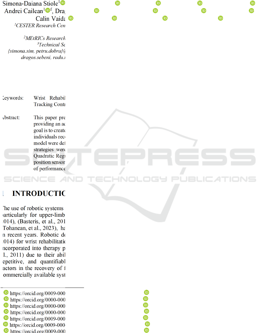
Figure 3: State and reference tracking under IJC.
This control strategy provided accurate tracking
for most of the states, with fast convergence and
minimal overshoot. Once the corresponding feedback
gain 𝐾 was obtained, the same controller was applied
to the original nonlinear model. The results confirm
that the control law remained effective, with the
system maintaining stability and accurate trajectory
tracking despite the presence of nonlinearities.
The state responses obtained using the LQR are
illustrated in Figure 4. The state trajectories are
plotted in blue, while the position reference signals
are in red. The IJC results show slower responses
compared to the LQR. All states converge to the
reference, with no overshoot and no steady state error,
confirming the effectiveness of the LQR design. The
settling times for each joint are about 0.47 sec for 𝑥
,
0.43 sec for 𝑥
, and 0.46 sec for 𝑥
.
After the LQR design, the next step was to
compute the observer gain 𝐿, based on the pole
placement. Specifically, the poles of the closed-loop
system with the state-feedback controller were
multiplied by a factor of 2 in magnitude. This pole
placement strategy ensures that the observer responds
relatively quickly to any deviations between the
measured and estimated outputs. Excessively fast
poles would increase estimation speed but also
demand high sampling rates and computational
power, which may not be feasible in a low-cost
implementation. The chosen configuration ensures
reliable state estimation while maintaining
compatibility with practical hardware constraints.
Figure 4: LQR-State trajectories and position reference.
As a result, the final poles of the observer are 𝑝 =
10
· [−9.07; −1.15; −0.20; −0.20; −0.21;0.09𝑖;
−0.21 + 0.09𝑖].
The gain observer matrix is:
𝐿=10
·
⎝
⎜
⎜
⎛
0.033 0.047 −0.651
0.086 0.098 0.574
0.068 0 0.975
0.111 0.886 −15.659
1.852 1.610 13.841
1.399 0.001 19.564
⎠
⎟
⎟
⎞
(21)
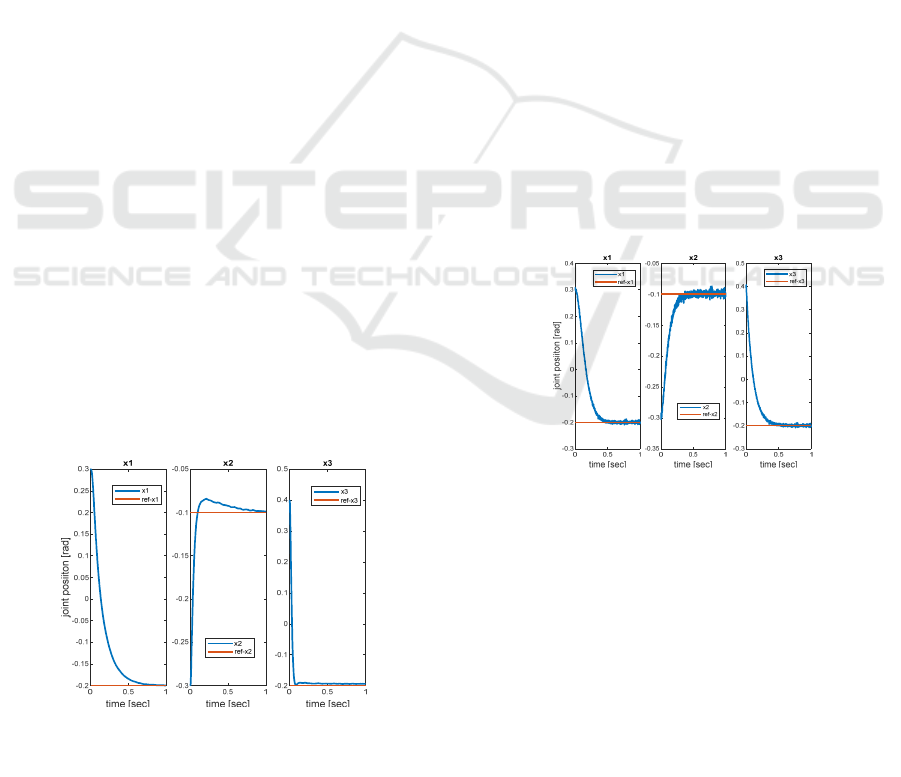
The results using the LQR controller together with
the Luenberger state observer are presented in Figure
6. The same feedback gain 𝐾, as a full state LQR, was
used with the same initial conditions.
ICINCO 2025 - 22nd International Conference on Informatics in Control, Automation and Robotics
224
In Figure 5, the positions (𝑥
,𝑥
,𝑥
) are plotted in
blue, the corresponding estimated states are shown in
red (coincide with the estimated states), and the
reference signals are displayed in magenta. The
simulation results show that the positions
successfully converge to the reference values without
steady-state error, and that the estimated states match
the true states, confirming the effectiveness of the
overall controller-observer structure. The closed-loop
performance achieved using the LQR controller in
combination with the Luenberger observer
demonstrates accuracy across all controlled joints.
The settling times are approximately 0.46 sec for 𝑥
,
0.41 sec for 𝑥
, and 0.47 sec for 𝑥
. Throughout the
simulation, none of the joint responses exhibited
overshoot or steady-state error.
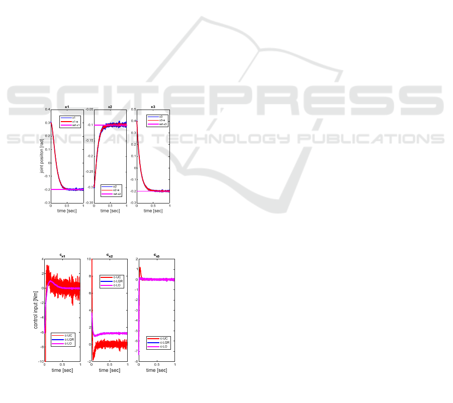
The estimation error (𝑥−𝑥
) generated by the
Luenberger observer is on the order of 10
. The
estimation error in all state components converges
toward zero. Figure 6 shows the control signals for
the three joints under each control strategy: the IJC
command is shown in red, the LQR command in blue,
and the LQR with observer in magenta (considered
best result in terms of noise reduction), with the last
two overlapping almost entirely. All signals remain
within the ±10 𝑁𝑚 range, which represents the
considered torque limit for the actuators.
Figure 5: System and estimated states and reference
trajectories for Luenberger observer.
Figure 6: Control signals for the system with the IJC, LQ
R
controller and LQR with Luenberger observer.
The IJC method stands out for its simplicity and
ease of implementation, providing fast response for
joint 𝑥
. However, it shows a significant overshoot
for 𝑥
and a small steady-state position error for 𝑥
,
highlighting the limitations of decoupled control.
The LQR achieves excellent overall performance,
with fast convergence, no overshoot, and zero steady-
state error, but it relies on full state feedback, which
may not be feasible in low-cost implementations.
In contrast, the LQR controller combined with a
Luenberger observer maintains similar performance
levels while using only joint position measurements.
This approach proves effective not only in reducing
sensor requirements but also in dealing with
modelling uncertainties and measurement noise,
making it highly suitable for practical, low-cost
rehabilitation systems.
5 CONCLUSIONS
This work presents the design, modeling, and control
simulation of a wrist rehabilitation robot developed
from scratch with emphasis on simplicity, low cost,
and compactness. The device is intended to support
repetitive wrist rehabilitation exercises, and to serve
as a practical solution for both clinical and home-
based rehabilitation.
Three control strategies were implemented in
simulation: IJC, LQR, and an observer-based LQR.
All proved feasible within the robot’s simplified
structure and intended use. IJC offers a
straightforward and accessible approach, while LQR
provides superior tracking accuracy and disturbance
rejection. The observer-enhanced LQR further
increases practicality by relying only on position
sensors, reducing hardware requirements while
maintaining performance.
These results establish a foundation for selecting
suitable control methods depending on application
priorities such as simplicity, precision, or sensor
economy. The findings will guide prototype
development, including the choice of motors, sensors,
and embedded hardware. They also highlight the
trade-offs between ease of implementation (IJC), high
control performance (LQR), and cost efficiency
(LQR + Observer). The next step is to build the
physical prototype and perform real-time testing,
initially with healthy users and later with patients
under clinical supervision.
Future work will expand the system’s capabilities
by including additional degrees of freedom and
modeling human–robot interaction forces to better
mimic realistic therapy. Integrating physiological
Design and Control of a New Wrist Rehabilitation Robot
225

feedback, such as electromyographic (EMG) signals,
could enable adaptive control strategies that adjust to
patient effort and fatigue. Long-term clinical studies
with healthcare professionals will also be pursued to
evaluate therapeutic outcomes and refine
rehabilitation protocols. Overall, the proposed system
demonstrates strong potential for becoming an
affordable and effective rehabilitation tool suitable
for deployment in hospitals and home-based recovery
programs.
ACKNOWLEDGEMENTS
This research was supported by the project New
frontiers in adaptive modular robotics for patient-
centered medical rehabilitation–ASKLEPIOS,
funded by European Union – NextGenerationEU and
Romanian Government, under National Recovery
and Resilience Plan for Romania, contract no.
760071/23.05.2023, code CF 121/15.11.2022, with
Romanian Ministry of Research, Innovation and
Digitalization, within Component 9, investment I8.
REFERENCES
Akdogan, E. (2016). Upper limb rehabilitation robot for
physical therapy: design, control, and testing. Turkish
Journal of Electrical Engineering and Computer
Sciences, 24(3), 911-934.
Basteris, A., et al (2014). Training modalities in robot-
mediated upper limb rehabilitation in stroke: a
framework for classification based on a systematic
review. J Neuroeng Rehabil, 11 111. doi:10.1186/1743-
0003-11-111
Franklin, G., Powell, J. D., & Emami-Naeini, A. (2014).
Feedback Control Of Dynamic Systems (7th ed.).
Prentice Hall Press.
Guozheng, X., et al (2014). Clinical experimental research
on adaptive robot-aided therapy control methods for
upper-limb rehabilitation. Robotica, 32(7), 1081–1100.
Krebs, H., et al (1999). Overview of clinical trials with
MIT-MANUS: a robot-aided neuro-rehabilitation
facility. Technology and Health Care, 419-423.
Levine, W. S. (2011). The Control Systems Handbook:
Control System Advanced Methods (2
nd
ed). CRC Press.
Major, Z. Z., et al (2021). Comparative Assessment of
Robotic versus Classical Physical Therapy Using
Muscle Strength and Ranges of Motion Testing in
Neurological Diseases. Journal of Personalized
Medicine, 11(10), 953.
Masiero, S., Armani, M., & Giulio, R. (2011). Upper-limb
robot-assisted therapy in rehabilitation of acute stroke
patients: Focused review and results of new randomized
controlled trial. Journal of Rehabilitation Research and
Development, 48(4), 355-366.
Mehrez, O., et al (2025). Development of an exoskeleton
for wrist-joint rehabilitation: modeling, identification,
and control. Multibody System Dynamics.
doi:10.1007/s11044-025-10066-0
Omarkulov, N., et al (2016). Preliminary mechanical
design of NU-Wrist: A 3-DOF self-aligning Wrist
rehabilitation robot. 2016 6th IEEE International
Conference on Biomedical Robotics and
Biomechatronics (BioRob), (pp. 962-967). Singapore.
Parisi, A., et al (2022). Efficacy of Multisensory
Technology in Post-Stroke Cognitive Rehabilitation: A
Systematic Review. Journal of Clinical Medicine,
11(21), 6324.
Pollock, A., et al (2014). Interventions for improving upper
limb function after stroke. Cochrane Database of
Systematic Reviews, 11(1).
Prewett, M. S., et al (2010). Managing workload in human–
robot interaction: A review of empirical studies.
Computers in Human Behavior, 26(5), 840-856.
Rosati, G., Gallina, P., & Masiero, S. (2007). Design,
Implementation and Clinical Tests of a Wire-Based
Robot for Neurorehabilitation. IEEE Trans. on Neural
Systems and Rehabilitation Eng., 15(4), 560-569.
Spong, M. W., Hutchinson, S., & Vidyasagar, M. (2005).
Robot Modeling and Control (First ed.). Wiley.
Squeri, V., et al (2014). Wrist rehabilitation in chronic
stroke patients by means of adaptive, progressive robot-
aided therapy. IEEE Transactions on Neural Systems
and Rehabilitation Engineering, 22(2), 312-325.
Tarnita, D., et al (2022). Analysis of Dynamic Behavior of
ParReEx Robot Used in Upper Limb Rehabilitation.
Applied Sciences, 12(15), 7907.
Tohanean, N., et al (2023). The Efficacity of the
NeuroAssist Robotic System for Motor Rehabilitation
of the Upper Limb—Promising Results from a Pilot
Study. Journal of Clinical Medicine, 12(2), 425.
Toth, A., et al (2005). Passive robotic movement therapy of
the spastic hemiparetic arm with REHAROB: report of
the first clinical test and the follow-up system
improvement. 9th International Conference on
Rehabilitation Robotics, 127-130. Chicago, IL, USA.
Tucan, P., et al (2022) Design and Experimental Setup of a
Robotic Medical Instrument for Brachytherapy in Non-
Resectable Liver Tumors. Cancers 2022, 14, 5841.
https://doi.org/10.3390/cancers14235841
Vaida C., et al (2018) Innovative development of a
spherical parallel robot for upper limb rehabilitation.
Int. J. Mech. Robot. Syst. 2018;4:256. doi:
10.1504/IJMRS.2018.096302.
Wu, C., et al (2011). Randomized Trial of Distributed
Constraint-Induced Therapy Versus Bilateral Arm
Training for the Rehabilitation of Upper-Limb Motor
Control and Function After Stroke. Neurorehabilitation
& Neural Repair, 25(2), 130-139.
ICINCO 2025 - 22nd International Conference on Informatics in Control, Automation and Robotics
226
