
Point Cloud Registration for Visual Geo-Referenced Localization
Between Aerial and Ground Robots
Gonzalo Garcia
a
and Azim Eskandarian
b
College of Engineering, Virginia Commonwealth University, 601 West Main Street, Richmond, U.S.A.
Keywords:
Monocular Visual SLAM, Autonomous Vehicles, Point Clouds.
Abstract:
Cooperative perception between aerial and ground robots relies on the accurate alignment of spatial data col-
lected from different platforms, often operating under diverse viewpoints and sensor constraints. In this work,
point cloud registration techniques for monocular visual SLAM-generated maps are investigated, which are
common in lightweight autonomous systems due to their low cost and sensor simplicity. However, monocular
visual SLAM outputs are typically sparse and suffer from scale ambiguity, posing significant challenges for
map fusion. We evaluate registration pipelines combining coarse global feature matching with local refine-
ment methods, including point-to-plane and plane-to-plane Iterative Closest Point alignments, to address these
issues. Our approach emphasizes robustness to differences in scale, density, and perspective. Additionally, we
assess the consistency of the resulting estimated trajectories to support geo-referenced localization across plat-
forms. Experimental results using datasets from both aerial and ground robots demonstrate that the proposed
methods improve spatial coherence by a factor of over 4 based on statistical metrics, and enable collaborative
mapping and localization in GNSS-intermittent environments. This work can contribute to advancing multi-
robot coordination for real-world tasks such as infrastructure inspection, exploration, and disaster response.
1 INTRODUCTION
Recent advances in autonomous robotics have in-
creasingly emphasized the interaction between aerial
and ground robots for complex tasks such as envi-
ronmental monitoring, infrastructure inspection, and
disaster response (Achtelik et al., 2011; Nex and Re-
mondino, 2014). In these heterogeneous systems, col-
laboration is critically dependent on a shared spatial
understanding of the environment. A central com-
ponent of this is the alignment of 3D data gener-
ated by each platform, typically in the form of sparse
or semi-dense point clouds. However, when relying
on monocular visual Simultaneous Localization and
Mapping (vSLAM) systems (Mur-Artal and Tard
´
os,
2017), common in lightweight, and low-power plat-
forms, the resulting point clouds are often subject to
scale ambiguity, noise, and viewpoint discrepancies,
making accurate point cloud registration a non-trivial
challenge (Kim and Kim, 2018).
Monocular vSLAM generates 3D maps from a se-
quence of 2D images without requiring depth sen-
a
https://orcid.org/0000-0001-9968-960X
b
https://orcid.org/0000-0002-4117-7692
sors or stereo systems, making it ideal for lightweight
aerial and ground autonomous vehicles. However,
due to its reliance on structure-from-motion, monocu-
lar SLAM often produces sparse and scale-ambiguous
point clouds (Scaramuzza and Fraundorfer, 2011).
When both aerial and ground robots use monoc-
ular vSLAM independently, fusing their respective
maps requires robust inter-frame alignment, capable
of compensating for different scales, viewing angles,
and reconstruction densities. This motivates the de-
velopment of point cloud registration techniques that
can operate effectively under such constraints to en-
able cooperative perception and geo-referenced local-
ization (Zhou et al., 2020).
This paper explores point cloud registration meth-
ods tailored for the alignment of monocular SLAM-
generated maps from aerial and ground robots. We
evaluated registration pipelines that combine coarse
feature-based alignment with fine-grained refinement
techniques such as point-to-plane ICP, and plane-to-
plane ICP (Rusinkiewicz and Levoy, 2001), all while
addressing the unique challenges posed by monocular
data, including inconsistent scale and sparse geome-
try. We also investigate the creation and consistency
of estimated trajectories as part of the localization as-
Garcia, G. and Eskandarian, A.
Point Cloud Registration for Visual Geo-Referenced Localization Between Aerial and Ground Robots.
DOI: 10.5220/0013693500003982
Paper published under CC license (CC BY-NC-ND 4.0)
In Proceedings of the 22nd International Conference on Informatics in Control, Automation and Robotics (ICINCO 2025) - Volume 2, pages 211-218
ISBN: 978-989-758-770-2; ISSN: 2184-2809
Proceedings Copyright © 2025 by SCITEPRESS – Science and Technology Publications, Lda.
211

pect of SLAM (Campos et al., 2021).
Our framework emphasizes cross-platform map
fusion by aligning independently generated vSLAM
point clouds into a unified coordinate system. This
enables collaborative localization, cooperative per-
ception, global map construction, and improved task
coordination between aerial and ground agents. Ex-
perimental indoor results demonstrate the viability of
our approach, showcasing improved alignment accu-
racy and mutual localization despite scale inconsis-
tencies and varying sensor perspectives.
By focusing on vSLAM-based point cloud reg-
istration, this work contributes to enabling more ac-
cessible and lightweight cooperative robotic systems,
empowering teams of monocular camera-equipped
aerial and ground-based autonomous vehicles to share
a unified understanding of their surroundings with
minimal sensor overhead.
2 VSLAM THEORY
This section reviews the essential theory required for
implementing monocular vSLAM and for compar-
ing two point clouds generated by autonomous ve-
hicles—one ground-based and one aerial—over the
same geographical area. One of the point clouds is
generated while the corresponding robot simultane-
ously estimates its position from a global positioning
system, making this point cloud geo-referenced. A
second point cloud, captured by the other vehicle, is
then registered to the first one using point cloud reg-
istration techniques (Jian and Vemuri, 2011). This al-
lows the second set of points to get geo-referenced,
without requiring the second robot to have explicit
knowledge of its own position.
2.1 Monocular VSLAM
SLAM, and in particular monocular visual SLAM,
performs two tightly coupled tasks during its opera-
tion: (1) constructing a 3D map of the environment
based on visual features extracted from a sequence
of images, typically represented as point clouds, and
(2) estimating the camera’s position by localizing it
within the evolving map. These recursive processes
rely heavily on two core concepts derived from stereo
vision: (i) calibrating a pair of consecutive, initially
uncalibrated images, and (ii) estimating the relative
pose (translation and orientation) of the camera be-
tween the two frames.
2.2 Stereo Calibration of Images
Although the theory was originally developed for two
separate cameras in arbitrary poses capturing overlap-
ping scenes, it can also be applied to a single cal-
ibrated camera moving through space, capturing a
sequence of images, and using pairs of consecutive
frames, effectively simulating the condition of spa-
tially separated cameras.
Calibrated stereo, often referred to as simple
stereo, is a special case of the uncalibrated stereo
scenario in which the two cameras are aligned with
identical orientations and a translation restricted to
the horizontal axis of the image plane, known as the
horizontal baseline b. Using the camera projection
matrix (Hartley and Zisserman, 2003), a system of
equations can be derived to estimate the 3D position
(x, y, z) of an object that appears in both images. This
task, known as the Correspondence Problem (Bach
and Aggarwal, 1988), is solved based on the matching
of the pixel coordinates between the two frames:
x =
b(u
l
− o
x
)
u
l
− u
r
, y =
b f
x
(v
l
− o
y
)
f
y
(u
l
− u
r
)
, z =
b f
x
u
l
− u
r
(1)
with ( f
x
, f
y
) the horizontal and vertical components of
the focal length of the camera, (o
x
, o
y
), the principal
point, and (u
l
, v
l
) and (u
r
, v
r
) the pixel coordinates of
the object in the left and right images (considering the
camera is moving from left to right).
When the camera is subjected to an arbitrary mo-
tion, the simple stereo calibration condition is lost,
and it has to be calibrated before applying the equa-
tions in (1). This process is called Image Rectification
(Szeliski, 2010).
Image rectification in computer vision refers to
the process of transforming images captured from two
different viewpoints so that the corresponding points
now lie on the same horizontal line, that is, they
share the same vertical coordinate v. This transfor-
mation simplifies the correspondence problem by re-
ducing the search for matching points from a two-
dimensional space to a one-dimensional search along
the common lines. As a result, the problem becomes
equivalent to a simple stereo configuration. Rectifi-
cation relies on the principles of Epipolar geometry
(Hartley and Zisserman, 2003).
Once the image pairs are rectified, the correspon-
dence problem can be addressed to generate candidate
3D points for the point cloud, using information ex-
tracted from each image individually. The key steps
are as follows: 1) Image distortion correction: Radial
distortion is typically corrected using the camera’s in-
ICINCO 2025 - 22nd International Conference on Informatics in Control, Automation and Robotics
212

trinsic parameters in (2),
K
camera
=
f
x
0 o
x
0 f
y
o
y
0 0 1
(2)
obtained through a process known as camera intrin-
sic calibration (Zhang, 2000). 2) Feature detection:
Salient features such as corners or regions with strong
gradients and textures are identified in each image.
In this work, 3D point associations are derived using
the Oriented FAST and Rotated BRIEF (ORB) fea-
ture detection method (Rublee et al., 2011). 3) Point
sampling: A uniformly spaced subset of the detected
feature points is selected to ensure even spatial distri-
bution. 4) Feature description: A feature extraction
algorithm, such as SIFT or SURF (Lowe, 2004; Bay
et al., 2006), is applied to compute feature descrip-
tors. These descriptors represent local image patches
around keypoints as numerical or binary vectors, fa-
cilitating reliable matching across views.
The next step involves matching the detected fea-
tures between the two images. This is typically per-
formed by computing the Hamming distances be-
tween all feature descriptors in one image and those
in the other, and then associating pairs based on the
minimum distance. From the resulting set of matched
pairs, the Essential matrix E and the Fundamental ma-
trix F are computed—both of which are fundamental
constructs in Epipolar geometry (Hartley and Zisser-
man, 2003).
2.3 Pose Calculation
Using these matrices, the pose of the camera at the
time the second image was captured can be estimated
relative to its pose during the first image. This process
yields the translation components T = [t
x
, t
y
, t
Z
]
T
and
the rotation matrix R, which are essential for gener-
ating the camera’s localization trajectory as it moves
through the environment.
Given a set of matching points shared between the
two images, (u
l
, v
l
) and (u
r
, v
r
), the Essential matrix
E in (3), and the Fundamental matrix F in (4), can be
estimated by solving the following equation, which
encapsulates the principles of Epipolar geometry:
u
l
v
l
1
K
−T
l
EK
−1
r
| {z }
F
u
r
v
r
1
T
= 0 (3)
or
x
l
y
l
z
l
E
x
r
y
r
z
r
T
= 0 (4)
Once the Essential matrix E is determined, the
Epipolar constraint further defines the following re-
lationship:
E =
0 −t
z
t
y
t
z
0 −t
x
−t
y
t
x
0
r
11
r
12
r
13
r
11
r
12
r
13
r
11
r
12
r
13
| {z }
R
(5)
This constraint (5) enables the recovery of the rel-
ative camera pose—specifically, the translation vec-
tor T and rotation matrix R, between the two views,
by doing singular value decomposition. This pose
estimation process is repeated across consecutive or
near-consecutive pairs of frames. By chaining the re-
sulting transformations, a 3D trajectory of the camera
can be constructed over time, representing the local-
ization component of the vSLAM system.
2.4 Point Cloud Registration Concept
Once the two point clouds are generated, the registra-
tion process can be initiated. The first point cloud,
produced by the ground vehicle, is geo-referenced
through an external positioning system that provides
accurate location data. The second point cloud, cap-
tured by the aerial drone, lacks global positional infor-
mation. The goal is to geo-reference the drone’s point
cloud by aligning it with the car’s geo-referenced map
using point cloud registration techniques.
The registration method employed in this work is
the Iterative Closest Point (ICP) algorithm, a widely
used technique for aligning two 3D point clouds. The
objective of ICP is to estimate the rigid transforma-
tion—comprising rotation and translation—that best
aligns a source point cloud to a target point cloud
by establishing point-to-point correspondences. The
standard ICP pipeline involves the following steps:
(1) Initial Alignment: Begin with an initial transfor-
mation guess, typically the identity matrix or a prior
estimate; (2) Closest Point Matching: For each point
in the source cloud, identify the closest point in the
target cloud; (3) Transformation Estimation: Com-
pute the rigid transformation that minimizes the mean
squared error between matched point pairs; (4) Apply
Transformation: Update the source point cloud using
the estimated transformation; and (5) Iteration: Re-
peat steps 2 through 4 until convergence, defined by a
threshold on the error reduction or a maximum num-
ber of iterations.
Several ICP variants exist based on the error met-
ric used, (Rusinkiewicz and Levoy, 2001). In partic-
ular, point-to-plane ICP minimizes the distance from
each point in the source cloud to the tangent plane
defined by the corresponding point and its local sur-
face normal in the target cloud. This approach lever-
ages surface geometry for improved convergence, es-
pecially in structured environments. Plane-to-plane
Point Cloud Registration for Visual Geo-Referenced Localization Between Aerial and Ground Robots
213
ICP extends this concept by incorporating planar ap-
proximations in both point clouds, minimizing the
misalignment between corresponding local surface
patches: Given a fixed point cloud p
i
, and a pair-wise
matched moving point cloud q
i
, i = 1 . . . N, plane-to-
plane ICP estimates the 3D rigid transformation A
A =
R T
0 1
(6)
by minimizing the following cost function in terms of
tangent planes around each pair of points, p
i
and q
i
:
E(R, T) =
∑
N
i=1
(q
i
− (R · p
i
+ T))
⊤
n
i
p
+R
⊤
n
i
q
∥
n
i
p
+R
⊤
n
i
q
∥
2
(7)
with n
i
p
and n
i
q
the surface normals at them. These
variants enhance robustness and accuracy in scenar-
ios involving sparse or noisy data, such as those gen-
erated by monocular vSLAM. These transformations
define the pose of the second point cloud relative to
the reference frame of the first point cloud, aligning
the two datasets within a common coordinate system.
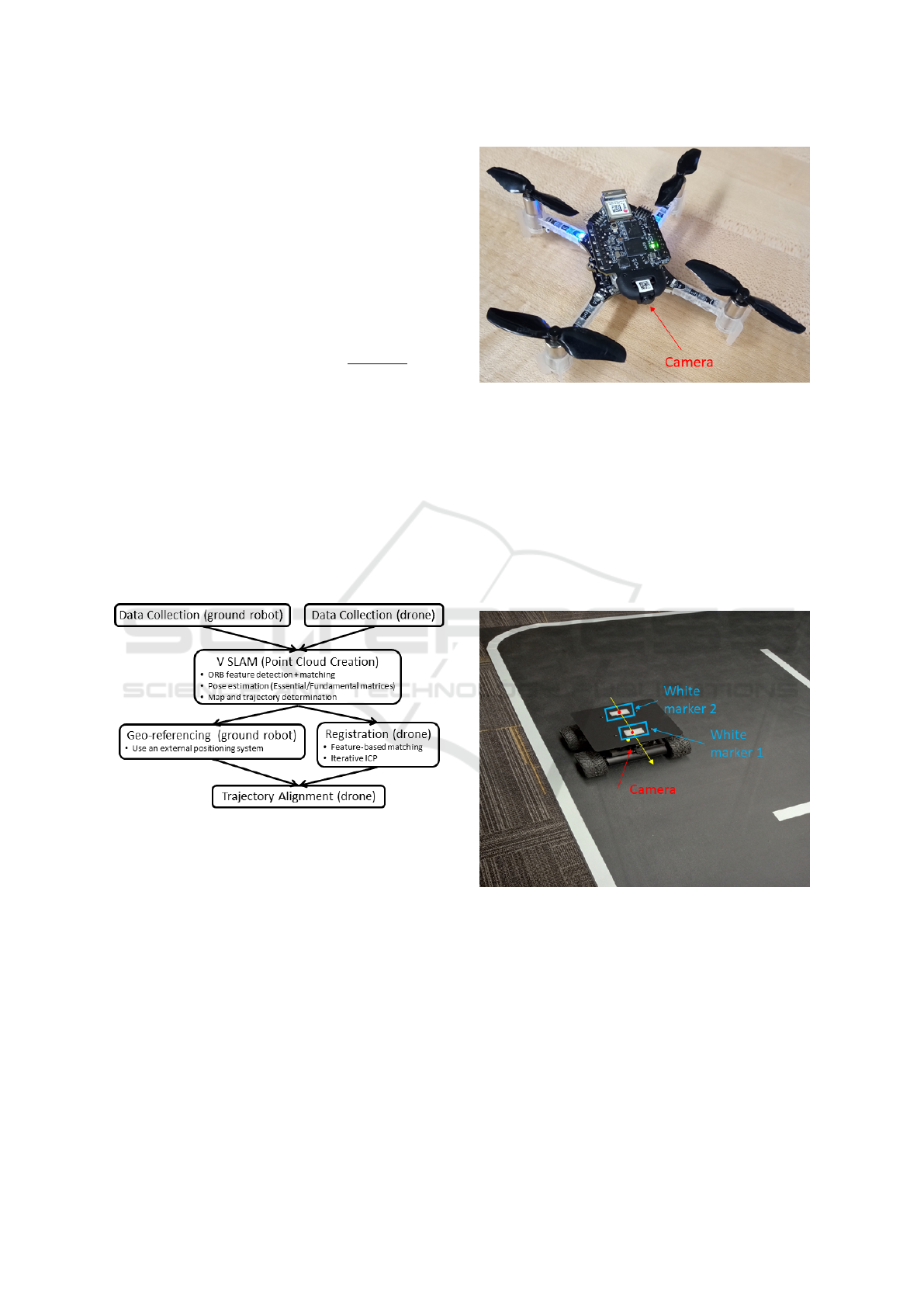
Figure 1 shows a pipeline of the process, including
data collection, point cloud creation, map and trajec-
tory determination, registration, geo-referencing, and
alignment:
Figure 1: Pipeline of the Visual Geo-referenced Localiza-
tion via Point Cloud Registration.
3 EXPERIMENT SETUP
The proof of concept for this cooperative percep-
tion research was conducted indoors using two au-
tonomous vehicles: a small ground robot and a nano-
drone. The ground vehicle is the Wifibot Lab V4
(https://www.wifibot.com), a four-wheel drive plat-
form, and the aerial platform is the Crazyflie 2.1 +, a
lightweight nanodrone (www.bitcraze.io). These plat-
forms are illustrated in Figures 2 and 3. The Crazyflie
2.1+ weighs only 27 grams and measures less than 5.5
inches from rotor to rotor, making it ideal for indoor
experimentation and agile flight.
Figure 2: Nano Drone Crazyflie 2.1+.
Both vehicles navigate autonomously through the
lab, collecting visual data from the same surrounding
area. Each robot is equipped with an onboard cam-
era for performing its own monocular vSLAM com-
putations. In addition, both are capable of determin-
ing their positions via an external positioning system.
This system consists of a ceiling-mounted camera that
tracks each vehicle as it moves and is connected to a
Lab computer that processes the video feed and com-
putes their positions.
Figure 3: White markers centroids are tracked to obtain the
robot position and heading.
A MATLAB script running on the Lab’s computer
initializes the tracking process. For the drone, a single
white marker is placed at its center. For the ground
vehicle, two white markers are affixed to the top of
the robot. These markers are detected and tracked us-
ing an alpha-beta filter that relies on black-and-white
contrast with the background during the experiments
(see Figure 3). By calculating the centroids of these
markers, the system can estimate the ground robot’s
position and heading.
ICINCO 2025 - 22nd International Conference on Informatics in Control, Automation and Robotics
214
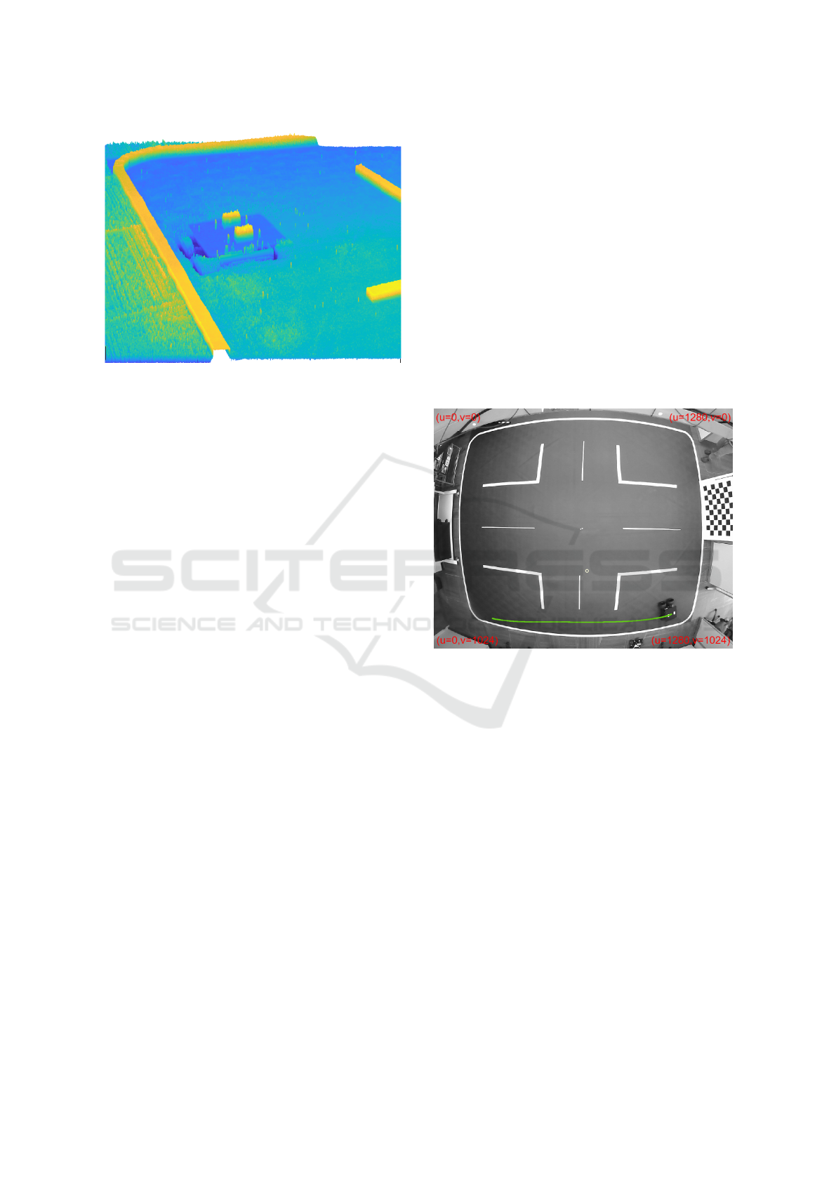
Figure 4: Grayscale converted image from Figure 3 (before
threshold Comparison).
Marker detection and tracking begin by convert-
ing the RGB image to grayscale, followed by apply-
ing a pixel-value threshold determined through exper-
imentation. Using the previously estimated marker
positions, a rectangular mask is applied to the binary
image to discard detections outside these predefined
regions. An additional filtering step checks that the
pixel count for each detected marker falls within a
specified range. The grayscale image is shown in Fig-
ure 4 (before applying the threshold). Small spuri-
ous detections are removed, while larger regions, such
as intersection boundaries, remain visible. To pre-
vent interference from these unwanted detections, a
masking procedure is applied once marker tracking
is initialized. This masking filters out all detections
outside a rectangular region centered on the mark-
ers. These rectangles, with sizes determined by ex-
periment, move dynamically with the markers as the
alpha-beta filter predicts and updates their estimated
positions over time, maintaining the rectangles cen-
tered on the detected markers.
The test is designed as follows: The ground vehi-
cle navigates following a trajectory while recording a
video of its surroundings. This video is processed to
generate a point cloud and a trajectory, which are ref-
erenced to the initial orientation of the camera. These
can then be geo-referenced to the Lab’s origin by us-
ing the external positioning system. As a feature of
vSLAM, the first camera orientation is maintained
as the reference for all subsequent poses. This geo-
referenced point cloud will serve as the baseline for
geo-referencing the drone’s point cloud. The drone
processes its own video similarly but does not rely
on external positioning data; instead, it registers the
point cloud with the point cloud of the ground vehicle
to correct its pose and achieve geo-referencing. The
externally calculated position of the drone, obtained
by the Lab’s positioning system, is only used in this
work to validate the precision of this approach. The
objective is to obtain a geo-referenced trajectory of an
autonomous vehicle through point cloud registration
with an existing geo-referenced point cloud of the en-
vironment. It is important to note that the roles of the
autonomous vehicles are interchangeable and could
be reversed.
4 EXPERIMENTAL RESULTS
This Section presents the main results of the research.
4.1 Fixed Point Cloud Calculation
Figure 5: Car trajectory. The starting point is at the left.
Figure 5 shows the trajectory of the ground vehicle
during the visual mapping obtained by the Lab po-
sitioning system. The effect of radial distortion pro-
duced by the camera can be seen, which is corrected
internally during the tracking process. The car started
on the lower left side of the image and moved to the
right while following the white lane, at a nearly con-
stant speed. It took a video of the scene to its right.
The position of the car is the midpoint between the
two markers, and the heading (not shown here) is ob-
tained by the angle subtended by them (Figure 3).
In this case, the first robot is required to serve as
a reference for the point cloud registration of the sec-
ond robot. For the integrity of these tests, it is as-
sumed that the surrounding scene remains unchanged
between the times the two videos are recorded.
As mentioned above, during the motion of the car,
a video sequence (that is, a series of images) is cap-
tured of the surroundings of the Laboratory, specifi-
cally on the right side of the vehicle. The camera is
Point Cloud Registration for Visual Geo-Referenced Localization Between Aerial and Ground Robots
215
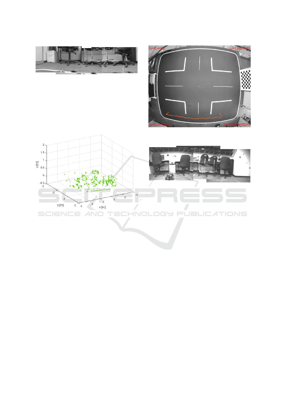
Figure 6: Superposition of Images Covering the Span of the
Video Captured from the Car.
mounted in such a way that it is rotated 90 degrees
to the right from the forward direction of the car. To
provide an idea of the scene perceived by the robot
while moving, a rough panoramic view was created
by quickly stitching together the first, last, and inter-
mediate frames from the video. This panoramic com-
posite is shown in Figure 6.
Figure 7: Point Cloud and Trajectory (starting at the right
of the graph) Captured by vSLAM from Car.
The video captured by the car, along with its cor-
responding positional data, is processed to generate a
point cloud that is geo-referenced to the Lab’s coordi-
nate system. The intrinsic matrix of the camera K
car
,
used for this computation, is obtained by a prior cal-
ibration process with ( f
x
= 479.75, f
y
= 479.92, o
x
=
323.18, o
y
= 177.88) in pixels. The video consisted
of 388 grayscale images, each with a resolution of
640 × 360 pixels. Figure 7 displays the point cloud
generated from this video. The resulting 3D points
are geo-referenced to the Lab’s coordinate system us-
ing the global position of the car.
4.2 Moving Point Cloud Calculation
The drone flew over the same region of the Lab, using
its onboard camera to capture the surrounding envi-
ronment. It took off vertically to a height of approx-
imately 0.5 meters, then moved horizontally like the
ground vehicle, before landing vertically. Figure 8
shows the trajectory of the drone, as recorded by the
Lab’s positioning system. The drone video had 399
Figure 8: Drone’s flight trajectory. The starting point is to
the left of the Trajectory.
Figure 9: Superposition of Images Covering the Span of the
Video Captured from the Drone.
images with a resolution of 324 × 244 pixels. Its in-
trinsic matrix K
drone
is given by ( f
x
= 180.95, f
y
=
180.94, o
x
= 159.23, o
y
= 155.72).
A panoramic view is shown in Figure 9. Feature
extraction and matching between consecutive frames
are a critical part of the vSLAM process.
Feature extraction returns descriptors, along with
their corresponding locations from a binary or inten-
sity image. These descriptors are computed from the
pixels surrounding each interest point, which is de-
fined by a single-point location representing the cen-
ter of a local neighborhood. The specific method used
to extract descriptors depends on the class or type of
the input points provided.
Then the matching step is used to identify and
match corresponding feature descriptors between two
sets of interest points extracted from images. It com-
pares the feature vectors and finds pairs that are most
similar according to a specified distance metric, such
as Hamming or Euclidean distance. The output is a
set of index pairs indicating which features from the
first image match those in the second image, enabling
tasks like image alignment, object recognition, and
3D reconstruction. Figure 10 shows the detected fea-
tures in two consecutive frames and their matching,
taken by the drone before taking off.
ICINCO 2025 - 22nd International Conference on Informatics in Control, Automation and Robotics
216
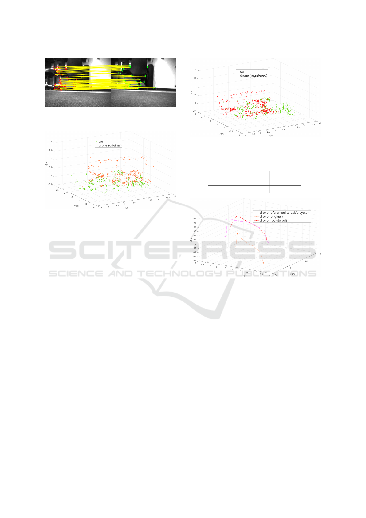
Figure 10: Detected and Matched Features in two Consec-
utive Frames from the Drone’s Camera.
Figure 11: Original Point Cloud Captured by Drone, and
Captured from the Car.
The point cloud obtained by the drone, refer-
enced with respect to its initial pose (i.e., not geo-
referenced), is shown in Figure 11, superimposed on
the point cloud generated by the car.
4.3 Point Cloud Registration
The registration performed by ICP algorithms gives
the following 3D rigid transformation (8), from (6):
A =
R T
0 1
=
0.995 −0.027 −0.097 −0.808
0.071 0.875 0.479 −0.261
0.072 −0.483 0.872 0.388
0 0 0 1
(8)
Figure 12 shows the car’s point cloud alongside
the drone’s point cloud after registration. Finally,
the 3D rigid transformation from (8) is used to geo-
reference the drone’s trajectory as calculated by vS-
LAM. This transformed trajectory is then reposi-
tioned within the Lab’s reference frame for compar-
ison. Figure 13 illustrates the following: (1) the
drone’s position with respect to the Lab, as measured
by the Lab’s external positioning system; (2) the orig-
inal vSLAM-based drone trajectory, without the cor-
rection; and (3) the geo-referenced drone trajectory,
obtained by applying the 3D transformation to the vS-
LAM output.
Mean Absolute Error (MAE) and Root Mean
Square Error (RMSE) metrics were calculated be-
tween the flown trajectory referenced to the lab
Figure 12: Registered Point Cloud from the Drone, and
Point Cloud from the Car.
Table 1: MAE and RMSE Metrics.
Metric Uncorrected Corrected
MAE 0.45 [m] 0.10 [m]
RMSE 0.46 [m] 0.09 [m]
Figure 13: Drone trajectory Referenced to the Lab’s Coor-
dinate System.
(ground truth), and both the uncorrected and corrected
ones, using the horizontal phase of the trajectories.
The results are shown in Table 1.
The corrected trajectory shows an improvement
in alignment with the Lab-based trajectory (ground
truth) by a ratio greater than 4 : 1, compared to the
uncorrected one, although some deviations remain.
The point cloud registration enables a successful geo-
referenced correction of the drone’s trajectory.
5 DISCUSSION AND
CONSIDERATIONS
Future advancements should focus on addressing the
following challenges to transition current research
into practical, real-world applications: (1) Environ-
mental Robustness: Future work should focus on en-
hancing the pipeline’s robustness to dynamic envi-
ronmental changes like moving objects, varying illu-
Point Cloud Registration for Visual Geo-Referenced Localization Between Aerial and Ground Robots
217

mination, and occlusions. Investigating adaptive fil-
tering or robust feature matching will be crucial for
maintaining performance and understanding failure
modes in the face of temporal inconsistencies. (2)
Computational Efficiency: Optimizing the pipeline
for real-time operation on embedded platforms is a
key next step. Exploring incremental registration, par-
allel computing, or hardware acceleration can reduce
latency, enabling live collaborative localization and
mapping, and balancing accuracy with computational
demands. (3) Uncertainty and Scalability: Quantify-
ing uncertainties in transformations and trajectories is
essential for downstream tasks. Propagating registra-
tion errors and integrating confidence metrics will im-
prove decision-making. Additionally, extending the
approach to fuse point clouds from multiple hetero-
geneous robots requires addressing scalability, con-
sistency, and conflict resolution.
6 CONCLUSIONS
This work presented a comprehensive study on point
cloud registration techniques tailored for visual geo-
referenced localization between aerial and ground
robots using monocular visual SLAM data. It was
demonstrated that combining coarse feature-based
alignment with fine-grained ICP refinements effec-
tively overcomes challenges associated with scale
ambiguity, sparse data, and viewpoint discrepancies
typical of monocular SLAM outputs. The experi-
mental evaluation on heterogeneous robotic platforms
confirmed that the approach improves map fusion ac-
curacy and enables consistent trajectory estimation,
crucial for cooperative perception and navigation in
environments with GNSS-denied or intermittent con-
ditions. These results highlight the potential of the
registration pipelines to enhance multi-robot coordi-
nation and collaborative mapping, supporting many
applications. Future work will focus on real-time im-
plementation and scalability to larger teams and dy-
namic environments.
REFERENCES
Achtelik, M., Bachrach, A., He, R., Prentice, S., and Roy,
N. (2011). Stereo vision and laser odometry for au-
tonomous helicopters in gps-denied indoor environ-
ments. In Unmanned Systems Technology XIII, vol-
ume 8045, page 80450H. SPIE.
Bach, W. and Aggarwal, J. K. (1988). Motion Understand-
ing: Robot and Human Vision. Springer Science &
Business Media, New York.
Bay, H., Tuytelaars, T., and Van Gool, L. (2006). Surf:
Speeded up robust features. Computer Vision – ECCV
2006, pages 404–417.
Campos, C., Elvira, R., Rodriguez, J. J. G., Montiel, J.
M. M., and Tard
´
os, J. D. (2021). Orb-slam3: An
accurate open-source library for visual, visual-inertial
and multi-map slam. IEEE Transactions on Robotics,
37(6):1874–1890.
Hartley, R. and Zisserman, A. (2003). Multiple View Geom-
etry in Computer Vision. Cambridge University Press,
2nd edition.
Jian, B. and Vemuri, B. C. (2011). Robust point set regis-
tration using gaussian mixture models. IEEE Trans-
actions on Pattern Analysis and Machine Intelligence,
33(8):1633–1645.
Kim, G. and Kim, A. (2018). Scan context: Egocentric spa-
tial descriptor for place recognition within 3d point
cloud map. In 2018 IEEE/RSJ International Confer-
ence on Intelligent Robots and Systems (IROS), pages
4802–4809. IEEE.
Lowe, D. G. (2004). Distinctive image features from scale-
invariant keypoints. International Journal of Com-
puter Vision, 60(2):91–110.
Mur-Artal, R. and Tard
´
os, J. D. (2017). Orb-slam2:
An open-source slam system for monocular, stereo,
and rgb-d cameras. IEEE Transactions on Robotics,
33(5):1255–1262.
Nex, F. and Remondino, F. (2014). Uav for 3d mapping
applications: a review. Applied Geomatics, 6(1):1–15.
Rublee, E., Rabaud, V., Konolige, K., and Bradski, G.
(2011). Orb: An efficient alternative to sift or surf. In
2011 International Conference on Computer Vision,
pages 2564–2571.
Rusinkiewicz, S. and Levoy, M. (2001). Efficient variants
of the icp algorithm. In Proceedings Third Interna-
tional Conference on 3-D Digital Imaging and Mod-
eling, pages 145–152. IEEE.
Scaramuzza, D. and Fraundorfer, F. (2011). Visual odome-
try [tutorial]. IEEE Robotics & Automation Magazine,
18(4):80–92.
Szeliski, R. (2010). Computer Vision: Algorithms and Ap-
plications. Springer, London.
Zhang, Z. (2000). A flexible new technique for camera cal-
ibration. IEEE Transactions on Pattern Analysis and
Machine Intelligence, 22(11):1330–1334.
Zhou, B., Wang, K., Wang, S., and Shen, S. (2020). Ro-
bust map merging for multi-robot visual slam in dy-
namic environments. IEEE Transactions on Robotics,
36(6):1649–1665.
ICINCO 2025 - 22nd International Conference on Informatics in Control, Automation and Robotics
218
