A Depth Image Processing Algorithm for Monitoring Product Flow on a
Conical Feeder Unit of a Multihead Weigher
Julia Isabel Hartmann
a
and Christoph Ament
b
Chair of Control Engineering, University of Augsburg, Universit
¨
atsstraße 2, 86159 Augsburg, Germany
Keywords:
Depth Image Processing, Multihead Weigher, Feeder, Multi-Object Tracking.
Abstract:
Cameras are widely used as sensors in both industrial and research settings for tasks such as quality inspection,
measurement, process monitoring, and control. Depending on the application, customized image processing
algorithms are required to extract quantitative measurement data from captured images. This paper presents
a novel depth image-based data acquisition algorithm for tracking the motion of multiple products on the
rotating conical feeder unit of a multihead weigher, an industrial weighing system composed of multiple
load cells. The acquired depth image data can be used for the parameter identification and verification of a
model, which simulates particle motion on the feeder surface. Future work aims at implementing the image
processing algorithm on a programmable logic controller to enable real-time tracking and integration with the
control system of the multihead weigher in an industrial environment.
1 INTRODUCTION
In the food industry, multihead weighers are often
used to weigh and proportion products to a specific
pack size. A multihead weigher represents an indus-
trial scale that enables the simultaneous weighing of
several partial amounts through multiple load cells.
Moreover, after weighing, the multihead weigher au-
tomatically combines a subset of the partial amounts
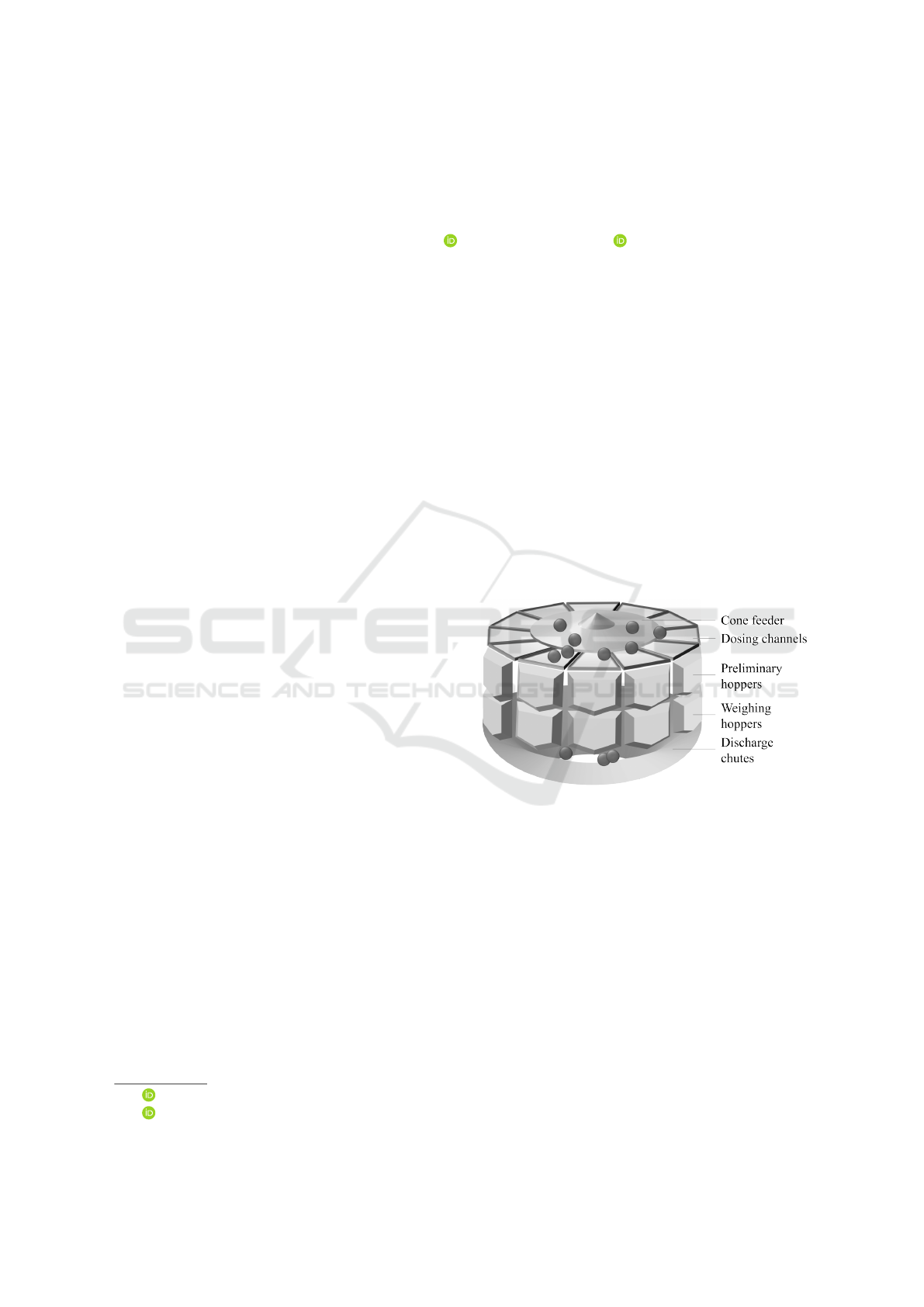
to a favorable weight. Within the multihead weigher,
the conical feeder unit is deployed at the beginning of
the product flow and distributes the falling products
radially outward into the dosing channels that lead
over preliminary hoppers to the weighing hoppers and
the load cells (see Figure 1). Thus, the feeder has
a profound impact on the product distribution among
the load cells. The weight distribution among the load
cells can, in turn, positively influence the combina-
tion process and the precise achievement of the target
weight. Furthermore, approaching the target weight
as closely as possible corresponds to a minimal prod-
uct giveaway and, thus, monetary savings.
Several aspects concerning the multihead weigher
have been addressed in the literature so far.
Machine topology. The determination of the op-
timal number of hoppers to be installed in a multi-
a
https://orcid.org/0009-0003-6848-833X
b
https://orcid.org/0000-0002-6396-4355
Figure 1: Layout of a multihead weigher.
head weigher has been formulated as a stochastic bi-
objective design optimization problem. This prob-
lem has been addressed using Monte Carlo simulation
techniques (van Niekerk et al., 2021).
Hopper setpoints. In each weighing cycle, a pre-
defined quantity of product is allocated to each weigh-
ing hopper, governed by its setpoint. To identify the
optimal hopper setpoints, various optimization strate-
gies have been applied, including Response Surface
Methodology (Beretta and Semeraro, 2012), heuristic
approaches (Del Castillo et al., 2017), gradient-based
algorithms, brute-force search, and random sampling
methods (Beretta et al., 2016). Furthermore, research
has been conducted on the use of both uniform and
variable setpoints across hopper subgroups (Garcia-
Diaz and Pulido-Rojano, 2020).
Hartmann, J. I. and Ament, C.
A Depth Image Processing Algorithm for Monitoring Product Flow on a Conical Feeder Unit of a Multihead Weigher.
DOI: 10.5220/0013678600003982
Paper published under CC license (CC BY-NC-ND 4.0)
In Proceedings of the 22nd International Conference on Informatics in Control, Automation and Robotics (ICINCO 2025) - Volume 2, pages 43-52
ISBN: 978-989-758-770-2; ISSN: 2184-2809
Proceedings Copyright © 2025 by SCITEPRESS – Science and Technology Publications, Lda.
43
Subset combination. The selection of the opti-
mal combination of hopper fillings to achieve a to-
tal weight that closely matches a specified target is
a central problem of the multihead weigher. Various
algorithmic approaches have been proposed, includ-
ing bit-wise operation-based combination algorithms
(Keraita and Kim, 2007) and dynamic programming
techniques (Imahori et al., 2010; Imahori et al., 2012;
Imahori et al., 2014). Bi-objective optimization meth-
ods have also been employed to minimize weight
variability while simultaneously accounting for the
residence time of products in the hoppers (Pulido-
Rojano et al., 2015; Pulido Rojano and Garcia Diaz,
2019; D
´
ıaz et al., 2017). In systems with a double
hopper layer, the packaging process has been for-
mulated as both a single-objective (An et al., 2024;
Garc
´
ıa-Jim
´
enez et al., 2021) and a bi-criteria opti-
mization problem, with solutions developed using dy-
namic programming (Karuno et al., 2010) and brute-
force search (Garc
´
ıa-Jim
´
enez et al., 2023). The prob-
lem of optimal simultaneous packaging of two prod-
ucts has been addressed using dynamic programming
(Imahori et al., 2010; Imahori et al., 2012), while
mixture packaging of two different products has been
explored using both dynamic programming (Imahori
et al., 2014) and a greedy heuristic (Karuno and Naka-
hama, 2020).
Variability reduction. Variability in the weigh-
ing process has been quantitatively assessed using
the Percentage Variability Reduction Index (Salicr
´
u
et al., 1996; Barreiro et al., 1998). In particular, the
impact of specific packaging strategies on variability
has been evaluated through a Six Sigma methodology
(Pulido-Rojano and Garcia Diaz, 2014). Additionally,
modified control charts have been employed to mon-
itor package weights under novel packaging strate-
gies aimed at reducing variability (Garc
´
ıa-D
´
ıaz and
Pulido-Rojano, 2017).
Feeder unit modeling. A dynamic friction model
with contacts has been proposed to model the motion
of a particle on a conical feeder for the viscoelastic
case (Hartmann et al., 2023). The model encompasses
a specific kinematic model for the conical feeder to
constantly calculate the constraint position, velocity,
and, thus, forces. Specifically, the overall model is
a nonlinear parameter-varying (NLPV) model and its
varying parameters have been identified by a multi-
stage optimization approach, considering the varying
parameters as functions of the initial position and con-
trol input of the system (Hartmann and Ament, 2025).
For the multi-stage parameter identification ap-
proach, measurement data is required. Given the na-
ture of the problem, a camera-based sensing solu-
tion is considered suitable for capturing the product
flow on the feeder unit. A depth-sensing camera is
preferred over a conventional area scan camera, as
it enables future extensions of the system for esti-
mating product weight on the feeder. In this paper,
an automatic image processing pipeline is proposed
to obtain the large dataset required for the identifi-
cation approach by extracting motion data from the
captured images. Furthermore, the image processing
algorithm is planned to support process monitoring
and control of the feeder unit during operation in the
future. The image processing algorithm has been suc-
cessfully adapted by the authors to operate on color
images as well.
This paper is organized as follows. Section 2 de-
scribes the hardware setup and the design of experi-
ments. Section 3 details the data acquisition process
based on the depth-image processing algorithm. Sec-
tion 4 presents the extension of the proposed image
processing approach to color images. Finally, Section
5 concludes the paper and provides an outlook on fu-
ture work.
2 HARDWARE AND DESIGN OF
EXPERIMENTS
2.1 Hardware Setup
At the University of Augsburg, a demonstrator of the
feeder unit with a diameter of 45 cm is available for
experimental testing. The demonstrator is an exact
replica of the feeder component used in an industrial
multihead weigher system. In industrial applications,
both rotating and vibrating feeder variants are em-
ployed, depending on the type of product being han-
dled. This research project focuses specifically on
challenging, sticky products, which are typically con-
veyed using a rotating cone feeder.
The demonstrator consists of a stepper motor with
a gearbox that drives a metal cone feeder, capable of
reaching a maximum rotational velocity of 290
◦
s
−1
.
For sensing, an Intel RealSense D435 stereo camera
is employed. In addition to capturing depth images,
the camera provides color images via its integrated
RGB module. The depth output supports resolutions
Figure 2: Hardware setup with initial placement of the spec-
imen.
ICINCO 2025 - 22nd International Conference on Informatics in Control, Automation and Robotics
44

up to 1280 × 720 px and frame rates of up to 90 fps,
with a depth accuracy of less than 2% at a distance of
2 m. In addition, the Intel RealSense software devel-
opment kit (SDK) is compatible with both MATLAB
and Python, facilitating integration into the data ac-
quisition and processing pipeline.
The D435 camera is selected for its wide depth
field of view (87
◦
× 58
◦
) and effective range of 0.3 m
to 3 m, which allows full coverage of the scene sur-
rounding the feeder without exceeding the spatial
constraints of the laboratory setup. The device is
mounted directly above the feeder, aligned vertically
downward, at a distance of 34.5cm from the apex of
the cone. The height of the cone is 6 cm.
To enhance image quality and avoid reflections,
the metal cone is covered with a matte black metal
foil. A foil seam running radially outwards from the
center to the cone edge is unavoidable, but is used
to align the cone with the start marker and to place
the specimen in the same position and orientation for
each measurement (see Figure 2).
2.2 Experimental Design
A small wooden plate (diameter: 3cm, height:
1.5cm, weight: 5.277g), which is covered by felt on
either side, is employed as a specimen. To control the
orientation of the specimen, an arrow marks the bot-
tom and angular orientation (see Figure 2).
Each experiment is conducted as follows. First, the
feeder foil seam is aligned with the start marker.
Then, the specimen is placed onto the foil seam with
the arrow pointing downwards. Finally, the depth
camera and data recording is started at a resolution
of 848 × 480 px and a frame rate of 90 fps and the
feeder is driven with a step reference velocity accord-
ing to the test plan. The reduced resolution is selected
because the maximum frame rate of 90 fps cannot be
achieved at the highest resolution. Nevertheless, the
chosen resolution provides sufficient spatial detail for
the task at hand.
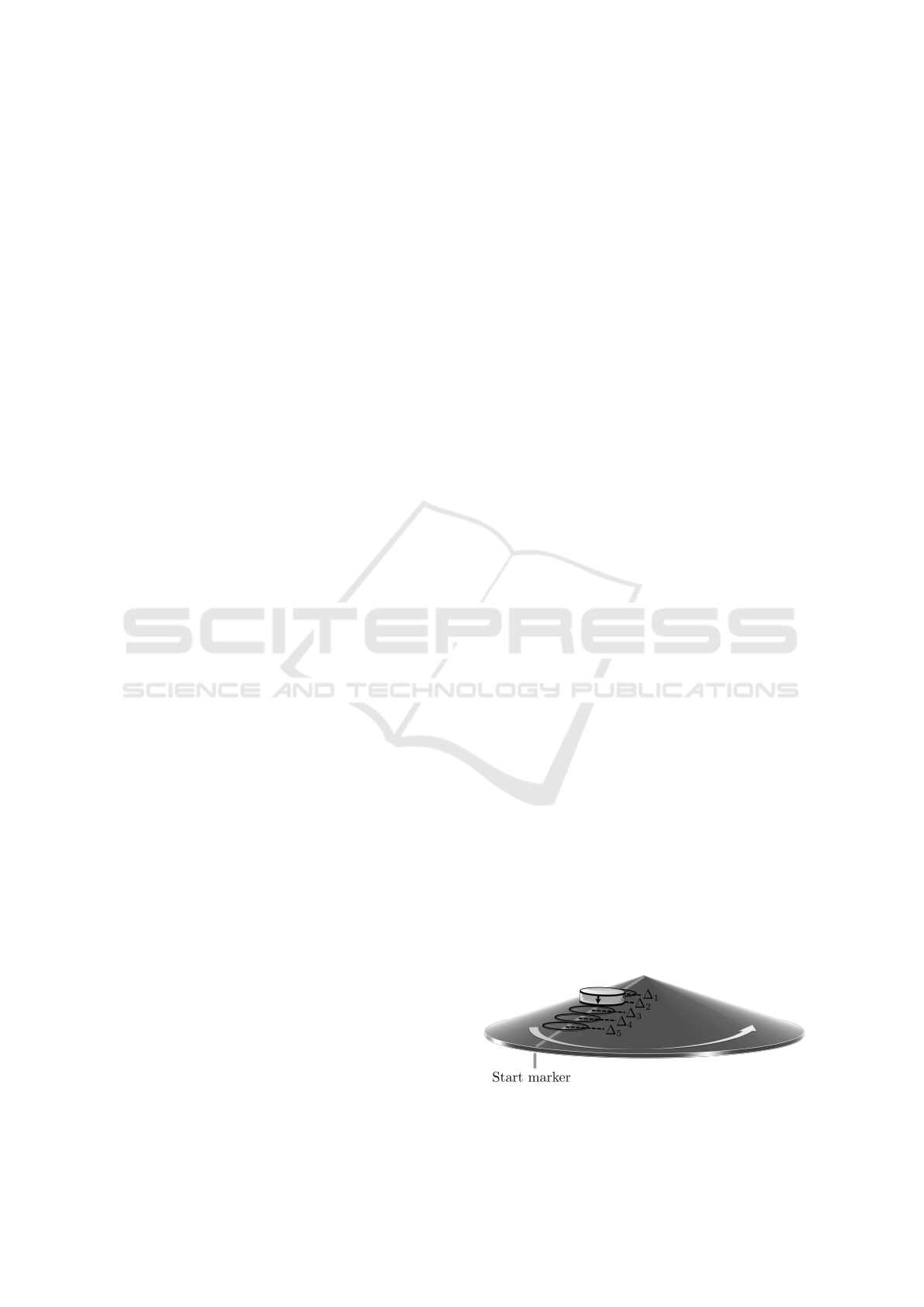
As in the parameter identification reference (Hart-
mann and Ament, 2025), regarding the test plan,
a full factorial design is followed, which considers
the two explanatory variables motor angular veloc-
ity ω and initial distance ∆ between the center of
the feeder and the centroid of the specimen. The
centroid of the specimen is projected onto the cone
surface for measuring the initial distance ∆. The
target variable is the position of the centroid of
the specimen. Five different initial distances ∆
i
of
4.5cm, 7.5 cm, 10.5 cm, 13.5cm and 16.5 cm are
used. Furthermore, the angular velocity of the motor
is varied from 100
◦
s
−1
to 290
◦
s
−1
in steps of 10
◦
s
−1
in either rotational direction. Note, that 100
◦
s
−1
is
selected as the lowest speed because at 100
◦
s
−1
the
specimen remains at its initial radial position regard-
less of the initial distance. Finally, each test point is
repeated n = 3 times. In total, 600 measurements are
conducted.
In each experiment, the depth frames of the feeder
are captured, processed by means of the hole filling
filter of the Intel RealSense SDK, and the angular ve-
locity of the motor and the assigned timestamps are
recorded for a predefined recording time. Afterwards,
the recorded data are processed offline by the custom-
made depth image processing algorithm. Hereby, the
algorithm can automatically detect multiple objects
in a depth frame and assign them to motion tracks
through an assignment algorithm. Multiple object
and track assignment and handling using an Extended
Kalman filter (EKF) is implemented as described in
(MathWorks, 2025c; MathWorks, 2025d).
3 DATA ACQUISITION AND
IMAGE PROCESSING
ALGORITHM
An overview of the depth image processing algorithm
is presented in Figure 3. The algorithm comprises
five main components. First, a calibration procedure
is performed. Subsequently, the necessary process-
ing tools and data structures are initialized. In the
next step, the depth frame is preprocessed to enhance
object visibility and enable reliable detection. After
object detection, the detections are assigned to exist-
ing tracks or used to initialize new ones. Finally, all
tracks, both active and inactive, are updated according
to the current results.
3.1 Calibration
For calibration purposes, a single depth frame show-
ing the empty feeder needs to be captured before or
after a measurement series. Based on this frame, a
semi-automatic calibration is performed once before
all measurements can be processed. At first, the left,
right, bottom, and top boundaries of the feeder are
defined manually as a rectangle to crop the frame to
the size of the feeder. Afterwards, the circular Hough
transform is applied to the cropped, sharpened, and
grayscale transformed frame to automatically identify
the circular boundary of the feeder, its center, and ra-
dius. If multiple circles are detected, the circle whose
center is closest to the center of the cropped image
is selected. If the selected circle is located too far
A Depth Image Processing Algorithm for Monitoring Product Flow on a Conical Feeder Unit of a Multihead Weigher
45
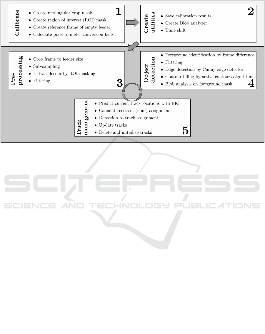
Figure 3: Image processing algorithm.
from the image center or its diameter is significantly
smaller than the width of the cropped image, the cal-
ibration is considered invalid, and manual calibration
is recommended. When a valid circle is identified,
a circular region of interest (ROI) mask is generated
based on the detected parameters. This mask is sub-
sequently used to isolate the feeder in later stages of
the image processing algorithm.
Moreover, for object detection, a reference frame
with the depth representation of the empty feeder
is necessary. For this purpose, the frame showing
the empty feeder is cropped to feeder size, median-
filtered to sub-sample and to reduce computational
burden, and small image defects, that have not been
removed by the initial hole filling of the Intel Re-
alSense SDK hole filling filter, are filled by sub-
sequent morphological image processing operations
(dilation with diamond-shaped structuring elements).
Next, an edge-preserving filtering using a bilateral fil-
ter with Gaussian kernels is performed to smooth the
image.
Finally, based on the reference frame, the pixel-to-
meter conversion factor c
f
is calculated with the cone
radius r
m
in meters and the radius r
px
of the identified
feeder boundary in pixels:
c
f
=
r
m
r
px
. (1)
Figure 4 illustrates the calibration process. Ini-
tially, the original frame, which contains defects and
irrelevant information outside the conical region, is
cropped using the white crop rectangle, as shown in
the first image. The resulting cropped image is de-
picted in the second panel. Subsequently, the circular
boundary of the cone is defined either manually or
automatically using a circular Hough transform. The
region inside the white circle in the third image marks
the region of interest for each frame. Finally, the ref-
erence frame obtained after cropping and filtering is
presented in the rightmost image.
3.2 Create Utilities
The calibration results are stored as utilities and in-
clude the crop rectangle, the center and radius of the
feeder in pixels, the ROI mask, the reference frame,
and the conversion factor.
Furthermore, a Blob analyzer object with a mini-
mum Blob area of 300 px is needed to identify image
regions with similar properties and, thus, to detect ob-
jects. It should be noted that the minimum Blob area
is dependent on the physical size of the sample and
can be estimated in advance based on the image reso-
lution and the area occupied by the sample within the
image. In addition, defining a maximum Blob area
can be beneficial, as it reduces the number of detected
Blobs during object detection, thereby decreasing the
computational load by limiting the number of candi-
dates that require further analysis.
Furthermore, the recorded timestamps are shifted
to a start time of 0s, to represent the time passed since
the start of the recording.
Moreover, empty data structs are initialized for the
ICINCO 2025 - 22nd International Conference on Informatics in Control, Automation and Robotics
46
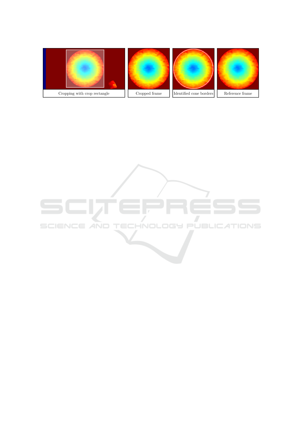
Figure 4: Calibration procedure.
tracks and deleted tracks. Each struct comprises sev-
eral fields storing information for object tracking:
• id: ID of the track,
• bbox: Current bounding box of the last detection,
• kalmanFilter: Kalman filter object for motion-
based object tracking,
• age: Number of frames since the track has been
initialized,
• totalVisibleCount: Number of frames in which
detections have been assigned to the track,
• consecutiveInvisibleCount: Number of consecu-
tive frames in which no detections have been as-
signed to the track,
• predictedCentroid: Predicted centroids of the de-
tections of this track,
• assignedCentroids: Centroids of the detections
assigned to the track,
• timeAssignedCentroids: Time stamps of the de-
tections assigned to the track,
• velocityAssignedCentroids: Rotational velocity of
the feeder, when the detection was assigned to the
track.
3.3 Preprocessing
From the preprocessing step onward, data are han-
dled frame by frame in a loop. At first, the frame
is cropped to feeder size and sub-sampled by a non-
zero median filtering. Then, the feeder image part is
extracted using the ROI mask. After the Intel Re-
alsense SDK hole filling filter remaining defects in
the depth image are filled by morphological dilation
and, if necessary, by inserting corresponding depth
values of the reference frame of the empty cone. Fi-
nally, edge-preserving filtering with Gaussian kernels
is performed to smooth the frame. Figure 5 illustrates
the preprocessing steps applied to a depth frame. Ow-
ing to the advanced filtering capabilities of the In-
tel RealSense SDK, the initial frame is of generally
high quality. A sample object, positioned near the left
boundary of the conical region, is highlighted with a
black bounding box. A minor image defect is visible
at the left edge of the object. Following region of in-
terest masking and morphological operations, the de-
fect is noticeably reduced. Subsequent application of
edge-preserving filtering further smooths and homog-
enizes the frame, effectively eliminating the defect.
3.4 Object Detection
The challenge in object detection lies in segmenting a
frame into the foreground (objects on the feeder) and
the background (the feeder itself). For this purpose, a
difference frame is calculated by subtracting the refer-
ence frame and the currently preprocessed frame. As
a result, the difference frame shows the deviation be-
tween the two frames, i.e. the foreground and, thus,
the objects on the feeder.
Then, the difference frame is refined by exclud-
ing negative depth values, noise (very small depth val-
ues), and all frame parts beyond the feeder boundary
by setting their depth values to 0. Next, a non-zero
median filter and an edge-preserving filter are applied
to reduce computational burden and enhance image
quality. In a subsequent step, the filtered frame is used
to detect edges through the Canny edge detector. Af-
terwards, the active contours (Snakes) region growing
technique is used to close the contour and fill it in.
Afterwards, small objects and holes are filled in by
a morphological opening with a disk-shaped structur-
ing element and a subsequent area opening operation,
which removes connected areas with less than a spec-
ified pixel size (150 px). The resulting binary mask is
the foreground mask of this frame.
Finally, Blob analysis is applied to the foreground
mask to find and analyze image areas with similar
properties (Blobs), which are the objects here. Then,
the identified Blobs are sorted out, in case they are
outside the cone boundaries, i.e. the distance between
the centroid of the blob and the cone center is larger
than the cone radius. Only for the remaining Blobs
a coordinate transformation is conducted to shift the
feeder center to the origin of the frame coordinate sys-
tem and to convert the positional values from pixel- to
A Depth Image Processing Algorithm for Monitoring Product Flow on a Conical Feeder Unit of a Multihead Weigher
47
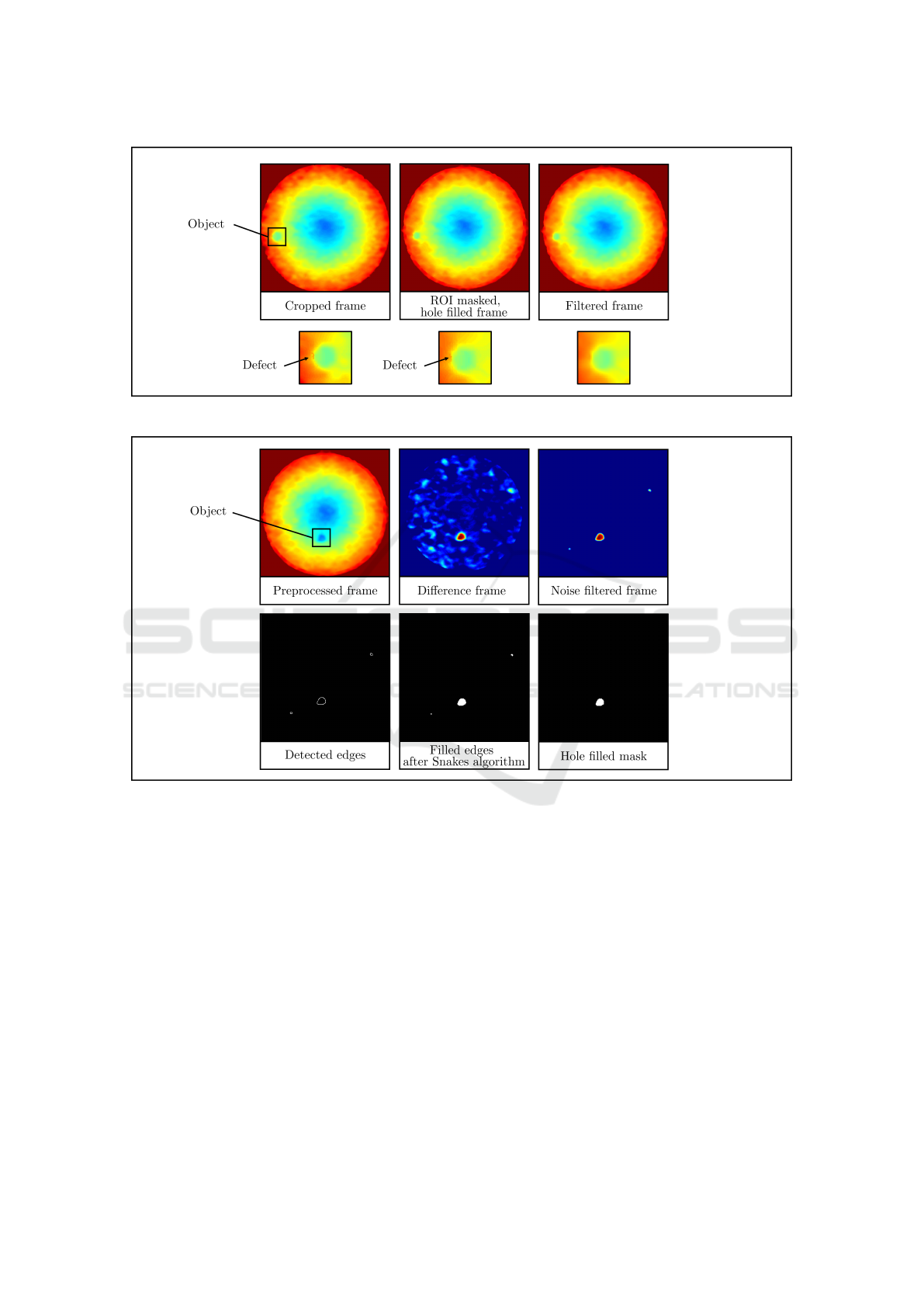
Figure 5: Preprocessing procedure.
Figure 6: Object detection procedure.
meter-scale. For the subsequent steps, the centroids,
bounding boxes, and areas of the Blobs are saved and
called detections in the following sections.
Figure 6 shows the object detection procedure step
by step.
3.5 Track Management
The motion-based multiple object tracking and
Kalman filter-based object tracking are described
in (MathWorks, 2025c; MathWorks, 2025d) and
adopted in this paper. Thereby, the detection to track
assignment is enhanced by validity checks that ensure
physically reasonable behavior of the objects. The re-
sulting track management process is described in de-
tail next.
Detections need to be assigned to existing or
newly created tracks, and tracks need to be updated
or opened accordingly. For this, the current position
of all tracks is predicted using an Extended Kalman
filter (MathWorks, 2025c). Then, the costs of assign-
ing each detection to each track must be calculated.
The costs are calculated based on the distance d(z)
between the centroid z of the detection and the pre-
dicted location x of the track, taking into account the
state covariance P, the measurement noise R, and the
measurement model H (MathWorks, 2025b)
d(z) = (z − Hx)
⊤
Σ
−1
(z − Hx) + ln(det(Σ)) (2)
Σ = HPH
⊤
+ R. (3)
Hereby, validity checks are necessary to ensure that
a track cannot move inwards towards the feeder cen-
ter or move faster than the motor speed. To prevent
inward movement, the radial positions of the last as-
ICINCO 2025 - 22nd International Conference on Informatics in Control, Automation and Robotics
48
signed detection of a track and the current detection
are compared. If the radial position of the detection
is smaller than the radial position of the track end mi-
nus a small offset of 5cm to compensate for measure-
ment noise, costs are set to a high penalty value of
100. Additionally, detections that would exceed the
maximum possible linear velocity v
max
resulting from
the surface velocity of the feeder in either the x- or
y-direction, when assigned to a track, incur penalty
costs of 100 as well. The maximum possible linear
velocity v
max
is calculated with the feeder rotational
velocity ω and the by the third dimension extended
current position r = [z
1
, z
2
, 0] of the detection
v
max
= ω × r. (4)
Finally, based on the assignment costs and the
fixed costs of 95 for non-assignment of a detec-
tion, the assignment problem is solved by a variant
of the Hungarian assignment algorithm (MathWorks,
2025a) and the assignments and unassigned detec-
tions are obtained. After this, the assigned tracks are
updated with the centroids of the assigned detections,
the current angular velocity of the feeder, and the
timestamp. In addition, the correction step of the Ex-
tended Kalman Filter is performed using the new de-
tection, while the age counter and total visible count
of the tracks are updated by 1 to monitor track lifes-
pan and visibility. The unassigned tracks need to be
updated as well by increasing their age and consecu-
tive invisible count by 1. A track is terminated and re-
moved if it has not been assigned a detection for more
than 20 frames, or if its visibility, defined as the ratio
of the number of frames in which it was visible to its
total age, falls below a predefined threshold of 60 %.
Once deleted, no further detections can be assigned to
the track. (MathWorks, 2025c)
Lastly, for each unassigned detection, a new track
is created and an Extended Kalman filter object is
initialized. For this purpose, a MATLAB Tracking
Extended Kalman filter is used with a constant
angular velocity model. The filter states are the
position r
x
in the x-direction and the y-direction r
y
in
meters, the velocity v
x
in x-direction and y-direction
v
y
in meters per second, and the angular velocity ω
in degree per second: x =
r
x
, v
x
, r
y
, v
y
, ω
.
A measurement corresponds to the position r of
the particle in all three spatial dimensions. The
z-position r
z
is needed for evaluating a cross product
in the subsequent steps. The state covariance is cho-
sen to P = diag
0.01, 1, 0.01, 1, 0.01
,
the process noise to Q =
diag
100, 0.01, 100, 0.01, 0.002
, and the
measurement noise to R = diag
100, 100, 100
.
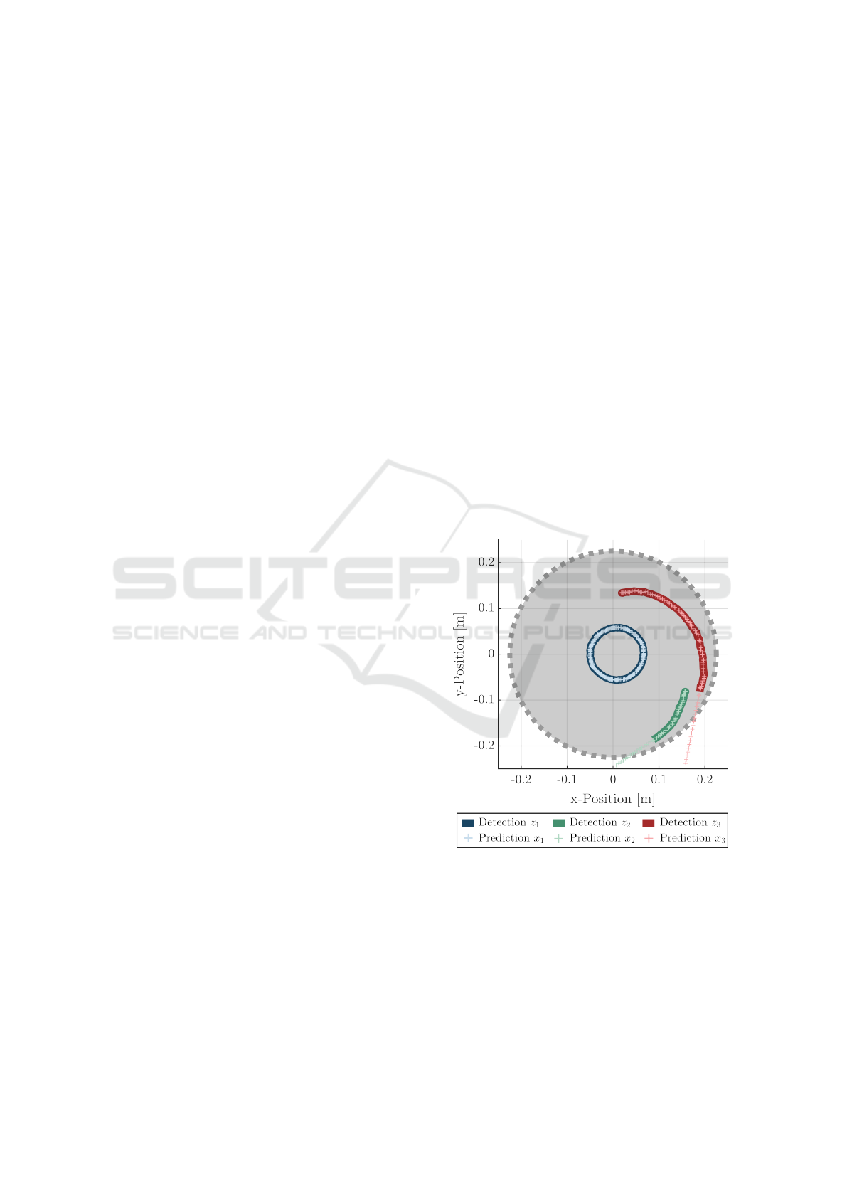
3.6 Multi-Object Tracking
Besides tests on a single specimen, the image pro-
cessing algorithm is evaluated using three samples of
similar type. The results of one experiment are pre-
sented in Figure 7. Each color represents a track, with
three tracks identified in total. Solid lines denote the
detections assigned to a track, while lighter-colored
plus signs indicate the corresponding Kalman filter
predictions. Each sample starts from a different ini-
tial position and exhibits either predominantly stick-
ing (blue) or sliding (green, red) behavior. The results
confirm that the algorithm successfully identified and
maintained three distinct tracks, each corresponding
to a specimen. The predictions closely follow the ob-
served motion and persist beyond the last detection,
until the track is formally terminated. This contin-
ued prediction appears consistent with the expected
object dynamics. However, for samples with varying
size or shape, the parameters of the Blob analysis and
filtering must be adapted to reliably distinguish valid
objects from noise. Additionally, scenarios involving
overlapping objects remain untested and present a di-
rection for future work.
Figure 7: Multi-object detection.
3.7 Detection of Different Objects
Although a round specimen is selected as the pri-
mary object for this study, the tracking algorithm is
not limited to spherical or circular shapes. To eval-
uate its generalizability, several static snapshots are
acquired using objects of varying shapes, surface ma-
terials, and heights. The test specimens include food
A Depth Image Processing Algorithm for Monitoring Product Flow on a Conical Feeder Unit of a Multihead Weigher
49
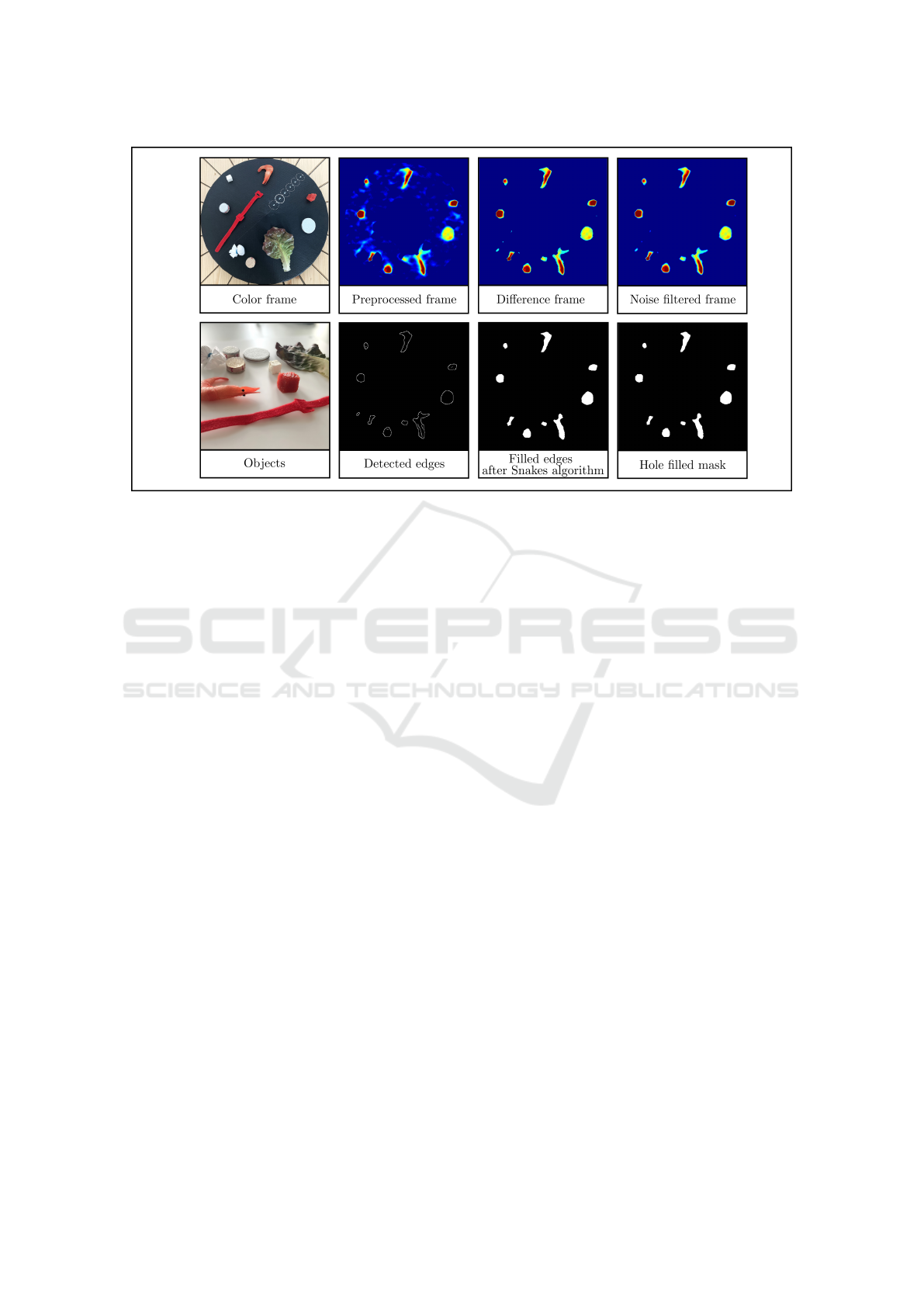
Figure 8: Object detection procedure for different objects.
dummies resembling a salad leaf, a shrimp, a piece
of meat, and a piece of feta cheese. Additionally,
wooden plates of different diameter, height, and sur-
face material, a small rice-filled bag, and a thin strip
of Velcro fastener tape are tested. As shown in Figure
8, all objects except for the thin Velcro fastener tape
are successfully detected. However, limitations arise
when the object thickness is too small, as observed
for the Velcro tape and the salad leaf. In particular,
the salad leaf is no longer detected as a single coher-
ent object.
4 EXTENSION TO COLOR
IMAGES
An adapted version of the proposed image processing
algorithm was also evaluated using color images. This
section outlines the necessary modifications required
to enable its application in the color image domain.
Calibration. In contrast to the depth image setup,
calibration for color images is more straightforward,
as no reference frame needs to be acquired. The re-
gion of interest mask is generated by identifying the
boundary of the cone feeder using circular Hough
transform applied to the binarized grayscale version
of the color image. The crop mask and the pixel-to-
meter conversion are determined analogously to the
depth image procedure.
Create utilities. The process of creating the utili-
ties remains unchanged.
Preprocessing. The preprocessing pipeline begins
by cropping the input image based on the defined
crop rectangle, followed by conversion of the cropped
color image to grayscale. The grayscale image is then
binarized, and the resulting binary image is masked
using the ROI mask. In initial tests, no additional fil-
tering was required, as the preprocessing output was
already of sufficient quality.
Object detection and tracking. Object detection is
carried out using Blob analysis on the preprocessed
binary frame. No further filtering or edge detection is
needed.
Track management. The track management logic
remains the same as in the original algorithm devel-
oped for depth images.
5 CONCLUSION
This paper presented an image processing algorithm
for multi-object tracking in depth images, specifically
designed for the application with a cone feeder of
a multihead weigher. The proposed method demon-
strates the feasibility of accurate offline object track-
ing and measurement data acquisition using a low-
cost, consumer-grade stereo camera. Additionally, a
pathway for extending the approach to color image
processing was outlined, enabling broader applicabil-
ity.
Despite the favorable price-performance ratio of
the selected hardware, particularly regarding reso-
lution and frame rate, several technical limitations
remain. These include non-deterministic frame ar-
rival, misordered timestamps, and the absence of a
ICINCO 2025 - 22nd International Conference on Informatics in Control, Automation and Robotics
50

GigE Vision interface, all of which currently restrict
real-time integration with a programmable logic con-
troller. Moreover, the Intel RealSense depth camera,
being a consumer-grade device, provides only lim-
ited depth accuracy (less than 2% at a distance of
2 m). In this study, it is employed for a preliminary
feasibility assessment of depth-based motion tracking
rather than for precise absolute height measurements.
For the intended application, high depth accuracy is
not critical, provided that the target objects are suffi-
ciently elevated to be reliably distinguished from the
feeder surface.
Due to the constraints of the research project, a
comparative evaluation with industrial-grade depth
cameras or stereo vision systems in terms of speed,
accuracy, and reliability was not feasible, as only the
Intel RealSense depth camera was available for inves-
tigation.
Nevertheless, the approach establishes a solid
foundation for future applications and developments.
The image processing algorithm is currently being
utilized for automatic parameter identification of a
nonlinear model describing particle dynamics on the
conical feeder, as demonstrated in (Hartmann and
Ament, 2025). Future work will focus on enabling
vision-based real-time control of the feeder unit.
This will require more sophisticated camera hardware
equipped with a GigE Vision interface to ensure de-
terministic data transmission and real-time compati-
bility with programmable logic controllers. Addition-
ally, porting the image processing algorithm to an em-
bedded programmable logic controller environment is
a necessary step toward industrial deployment.
Further research will explore automatic product
identification during the operation of the multihead
weigher. By leveraging depth data, projected object
area, and estimated material density, the method also
offers the potential for approximating the weight of
individual items. This capability could improve the
dynamic distribution of product weight into individ-
ual hoppers, ultimately contributing to more efficient
and adaptive packaging processes.
ACKNOWLEDGEMENTS
This work is part of the project “KiKO.BD - KI-
Kombinationswaage mittels Big Data” of the pro-
gramme “BayVFP F
¨
orderlinie Digitalisierung” of
Bavarian Ministry of Economic Affairs, Regional De-
velopment and Energy.
REFERENCES
An, P., Hong, C.-J., Ri, R.-Y., Yu, C.-J., and O, C.-
J. (2024). An improved single objective optimiza-
tion approach for double-layered multi-head weighing
process. Mathematical Modelling and Applications,
9(3):61–69.
Barreiro, J. J., Gonz
´
alez, C., and Salicr
´
u, M. (1998). Opti-
mization of multiweighing packing proceedings. Top,
6(1):37–44.
Beretta, A. and Semeraro, Q. (2012). On a rsm approach
to the multihead weigher configuration. In Volume
1: Advanced Computational Mechanics; Advanced
Simulation-Based Engineering Sciences; Virtual and
Augmented Reality; Applied Solid Mechanics and Ma-
terial Processing; Dynamical Systems and Control,
pages 225–233. American Society of Mechanical En-
gineers.
Beretta, A., Semeraro, Q., and Del Castillo, E. (2016). On
the multihead weigher machine setup problem. Pack-
aging Technology and Science, 29(3):175–188.
Del Castillo, E., Beretta, A., and Semeraro, Q. (2017). Op-
timal setup of a multihead weighing machine. Euro-
pean Journal of Operational Research, 259(1):384–
393.
D
´
ıaz, J. C. G., Rojano, A. P., and Bosch, V. G. (2017).
Bi-objective optimisation of a multihead weighing
process. European J. of Industrial Engineering,
11(3):403.
Garc
´
ıa-D
´
ıaz, J. C. and Pulido-Rojano, A. (2017). Mon-
itoring and control of the multihead weighing pro-
cess through a modified control chart. DYNA,
84(200):135–142.
Garcia-Diaz, J. C. and Pulido-Rojano, A. D. (2020). Perfor-
mance analysis and optimisation of new strategies for
the setup of a multihead weighing process. European
J. of Industrial Engineering, 14(1):58–84.
Garc
´
ıa-Jim
´
enez, R., Garc
´
ıa-D
´
ıaz, J. C., and Pulido-Rojano,
A. D. (2021). Packaging process optimization in mul-
tihead weighers with double-layered upright and diag-
onal systems. Mathematics, 9(9):1039.
Garc
´
ıa-Jim
´
enez, R., Garc
´
ıa-D
´
ıaz, J. C., and Pulido-Rojano,
A. D. (2023). Bicriteria food packaging process opti-
mization in double-layered upright and diagonal mul-
tihead weighers. Journal of Computational and Ap-
plied Mathematics, 428:115168.
Hartmann, J. I. and Ament, C. (2025). Automatic parameter
identification of a nonlinear parameter-varying model
for a rotating cone feeder [accepted]. In IEEE/IFAC
9th International Conference on Control Automation
and Diagnosis (ICCAD’25).
Hartmann, J. I., Olbrich, M., Hamann, M., and Ament,
C. (2023). Simulation of particle motion on rotat-
ing cone feeder for a multihead weigher based on dy-
namic friction modeling. In 2023 IEEE/ASME Inter-
national Conference on Advanced Intelligent Mecha-
tronics (AIM), pages 138–143. IEEE.
Imahori, S., Karuno, Y., Nishizaki, R., and Yoshimoto, Y.
(2012). Duplex and quasi-duplex operations in au-
tomated food packing systems. In 2012 IEEE/SICE
A Depth Image Processing Algorithm for Monitoring Product Flow on a Conical Feeder Unit of a Multihead Weigher
51

International Symposium on System Integration (SII),
pages 810–815. IEEE.
Imahori, S., Karuno, Y., and Tateishi, K. (2014). Dynamic
programming algorithms for producing food mixture
packages by automatic combination weighers. Jour-
nal of Advanced Mechanical Design, Systems, and
Manufacturing, 8(5):JAMDSM0065–JAMDSM0065.
Imahori, S., Karuno, Y., and Yoshimoto, Y. (2010). Dy-
namic programming algorithms for duplex food pack-
ing problems. In 2010 8th IEEE International Confer-
ence on Industrial Informatics, pages 857–862. IEEE.
Karuno, Y., Nagamochi, H., and Wang, X. (2010). Opti-
mization problems and algorithms in double-layered
food packing systems. Journal of Advanced Mechan-
ical Design, Systems, and Manufacturing, 4(3):605–
615.
Karuno, Y. and Nakahama, O. (2020). An improved
performance of greedy heuristic solutions for a bi-
criteria mixture packaging problem of two types of
items with bounded weights. Journal of Advanced
Mechanical Design, Systems, and Manufacturing,
14(5):JAMDSM0066–JAMDSM0066.
Keraita, J. N. and Kim, K. H. (2007). A weighing algorithm
for multihead weighers. International Journal of Pre-
cision Engineering and Manufacturing, 8(1):21–26.
MathWorks (2025a). assigndetectionstotracks - as-
sign detections to tracks for multiobject track-
ing. https://de.mathworks.com/help/vision/ref/assign
detectionstotracks.html, 17.05.2025.
MathWorks (2025b). distance - con-
fidence value of measurement.
https://de.mathworks.com/help/vision/ref/vision.
kalmanfilter.distance.html, 17.05.2025.
MathWorks (2025c). Motion-based multiple object track-
ing. https://de.mathworks.com/help/vision/ug/motion-
based-multiple-object-tracking.html, 15.01.2025.
MathWorks (2025d). Use kalman filter for object track-
ing. https://de.mathworks.com/help/vision/ug/using-
kalman-filter-for-object-tracking.html, 15.01.2025.
Pulido Rojano, A. and Garcia Diaz, J. C. (2019). Opti-
misation algorithms for improvement of a multihead
weighing process. International Journal of Produc-
tivity and Quality Management, 1(1):1.
Pulido-Rojano, A., Garcia-Diaz, J. C., and Giner-Bosch, V.
(2015). A multiobjective approach for optimization
of the multihead weighing process. In 2015 Interna-
tional Conference on Industrial Engineering and Sys-
tems Management (IESM), pages 426–434. IEEE.
Pulido-Rojano, A. D. and Garcia Diaz, J. C. (2014). Op-
timization of multihead weighing process using the
taguchi loss function. In 8th International Conference
on Industrial Engineering and Industrial Management
XX International Conference on Industrial Engineer-
ing and Operations Management International IIE
Conference 2014, pages 305–312.
Salicr
´
u, M., Gonz
´
alez, C., and Barreiro, J. J. (1996).
Variability reduction with multiweighing proceedings.
Top, 4(2):319–329.
van Niekerk, J. E., van Vuuren, J. H., and Lindner, B. G.
(2021). Optimizing the number of hoppers on a multi-
head weighing machine. Journal of Industrial and
Production Engineering, 38(6):401–413.
ICINCO 2025 - 22nd International Conference on Informatics in Control, Automation and Robotics
52
