
Sensorless Admittance Control of a Manipulator Arm Using a Nonlinear
Observer for Force and Velocity Estimation
Brahim Brahmi
1,2 a
1
Department of Electrical Engineering, King Fahd University of Petroleum & Minerals, Dhahran, Saudi Arabia
2
Center for of nterdisciplinary Research Center on Intelligent Manufacturing and Robotics, King Fahd University of
Petroleum & Minerals, Dhahran, Saudi Arabia
Keywords:
Nonlinear Observer, Admittance Control, Human-Robot Interaction, Force Estimation, Rehabilitation
Robotics.
Abstract:
This paper presents a nonlinear observer-based approach for estimating force and velocity in a joint-space
admittance-controlled exoskeleton, designed to support safe and compliant physical human–robot interaction.
The observer estimates external interaction forces and joint velocities using only joint position measurements,
eliminating the need for external force or velocity sensors. Integrated into the ETS-MARSE upper-limb reha-
bilitation exoskeleton, the system generates compliant motion trajectories in response to user-applied forces.
An experiment involving a human subject was conducted to validate the observer’s accuracy. The estimated
forces and velocities were compared with reference sensor measurements. Results demonstrate that the ob-
server provides reliable state estimates, enabling accurate tracking of motion and interaction forces with low
error and high responsiveness. The system maintains compliant behavior, supporting natural, user-driven
movement without compromising stability. This work highlights the potential of sensorless estimation in
robotic rehabilitation and interaction-intensive control applications.
1 INTRODUCTION
The emergence of advanced technologies—including
collaborative robotic arms, versatile robotic hands,
and wearable rehabilitation robots—has led to their
growing application in physically interactive tasks
across various settings (Ibarguren et al., 2020; Qin
et al., 2021; Li et al., 2022b). Performing complex
tasks such as rehabilitation, adaptive object handling,
and human engagement often requires precise control
and stabilization of contact forces (Chen et al., 2020).
Unlike soft robots, which rely on material flexibility
to absorb impacts, robotic manipulators depend on
rigid structures to achieve operational precision (Si-
ciliano and Villani, 2000). However, this reliance on
rigidity can pose challenges in sensitive operations
such as grinding or machining, where maintaining
a specific trajectory while applying precise forces is
critical (Jaroonsorn et al., 2020).
In human–robot collaboration, a central challenge
lies in enabling the robot to interpret the human
partner’s movement intentions, allowing it to engage
in proactive cooperation. Simply programming the
a
https://orcid.org/0000-0002-4486-0710
robot to follow predefined trajectories is ineffective
in such dynamic interactions. While force control
can regulate interaction forces, its effectiveness is
often limited by poor robustness (Newman, 1992).
Impedance control—originally introduced in (Hogan,
1985) and later refined in numerous studies (Jung and
Hsia, 2000; Lynch et al., 2002)—has emerged as a
widely accepted method for managing interaction dy-
namics. This approach allows the robot to exhibit
compliant behavior in response to external forces ap-
plied by the human partner, enabling smooth collab-
oration by adapting to human-driven motions. How-
ever, since impedance control adjusts the robot’s re-
sponse based on external forces, it inherently resists
sudden motion changes initiated by the user, effec-
tively behaving as an additional inertial load (Iqbal
and Zheng, 1999). Moreover, in human–robot contact
scenarios where physical properties such as stiffness
or position are not precisely known, unpredictable in-
teractions can lead to excessive stress on joint actua-
tors or even cause damage to contact interfaces (Xue
et al., 2020). To mitigate such risks, it is essential
for the system to maintain compliance or dynamically
adapt its impedance characteristics throughout the in-
Brahmi, B.
Sensorless Admittance Control of a Manipulator Arm Using a Nonlinear Observer for Force and Velocity Estimation.
DOI: 10.5220/0013669200003982
Paper published under CC license (CC BY-NC-ND 4.0)
In Proceedings of the 22nd International Conference on Informatics in Control, Automation and Robotics (ICINCO 2025) - Volume 2, pages 15-23
ISBN: 978-989-758-770-2; ISSN: 2184-2809
Proceedings Copyright © 2025 by SCITEPRESS – Science and Technology Publications, Lda.
15

teraction. This adaptability enables better regulation
of contact forces, preventing the aforementioned me-
chanical issues (Hongli, 2022). Additionally, estimat-
ing the human partner’s movement intention and inte-
grating this estimation into the robot’s control strategy
is critical to overcoming such limitations.
Admittance control has become a key strategy in
rehabilitation robotics, enabling active user partic-
ipation, task repeatability, and outcome quantifica-
tion (e.g., improvement, effort) (Ozkul and Barkana,
2013). Despite its advantages, certain limitations per-
sist—such as restricted degrees of freedom or ex-
clusive implementation in end-effector-based systems
(Culmer et al., 2010). Various human–robot inter-
action modalities have evolved over time, ranging
from joysticks to advanced biosignals such as EMG
(Karimi and Ahmadi, 2025) and EEG (Hsu et al.,
2025). Among them, force sensors remain widely
used (Zarrin et al., 2024), particularly in support-
ing compliant control through impedance or admit-
tance schemes (Otten et al., 2015). Numerous reha-
bilitation and robotic systems incorporate force sen-
sors to enable compliant interaction. For example,
the iPAM system integrates dual 6-DOF force sen-
sors for bilateral control (Zarrin et al., 2024); Re-
habRoby uses one-axis sensors at the elbow and
shoulder joints (Ozkul and Barkana, 2013); and the
EXO-UL7 includes four 6-axis sensors at key attach-
ment points (Miller and Rosen, 2010). Similarly, the
ETS-MARSE platform features a 6-DOF force sen-
sor to support compliant control strategies (Brahmi
and Saad, 2023). Although these sensors enhance
safety and control precision, they present notable
drawbacks—they are costly, susceptible to thermal
drift and noise, and mechanically fragile, all of which
may compromise performance and safety in physical
human–robot interaction (Katsura et al., 2007).
To address these limitations, nonlinear observer-
based approaches have been explored in industrial
settings as sensorless alternatives for force estima-
tion (Alcocer et al., 2003; Chen et al., 2000). Their
use in rehabilitation robotics has also gained inter-
est. For instance, a nonlinear disturbance observer
was implemented in (Gupta and O’Malley, 2011) to
regulate external forces in a single-DOF rehabilita-
tion setup. In a more complex scenario, (Popescu
et al., 2013) utilized a combination of three nonlinear
observers—a force observer, a velocity observer, and
a force-disturbance observer—to control a hand ex-
oskeleton, enhancing performance without relying on
physical force sensors. Recent trends also explore re-
inforcement learning combined with impedance con-
trol to adapt impedance gains for improved accuracy
and efficiency (Li et al., 2022a; Zhang, 2021). How-
ever, these methods face challenges including lim-
ited interpretability, safety concerns due to extensive
physical interaction, and lack of guaranteed conver-
gence or robustness against overfitting.
In this paper, we propose a nonlinear observer for
the ETS-MARSE rehabilitation robot to estimate ex-
ternal interaction forces without relying on force or
velocity sensors. Using only joint position measure-
ments, the proposed observer reduces computational
complexity while maintaining performance. The esti-
mated forces are used to infer the user’s movement in-
tention and to implement a compliant control strategy,
facilitating natural human–robot interaction. This ap-
proach simplifies the traditional admittance control
framework by removing the need for Cartesian-to-
joint space transformations via Jacobian inversion, as
joint torques can be directly estimated through the ob-
server. The robot’s impedance behavior is tuned to
support isokinetic-type exercises, ensuring an appro-
priate dynamic response. To further improve estima-
tion accuracy, the observer is augmented with feed-
back from the controller’s internal model, enabling it
to distinguish between user-generated forces and in-
ternal disturbances such as friction or unmodeled dy-
namics. This enhances both reliability and control
performance in assistive rehabilitation tasks.
The structure of the paper is as follows: Section
2 introduces the core problem, detailing the adopted
nonlinear control strategy, the dynamic model of the
rehabilitation robot, its key properties and assump-
tions, and the formulation of the admittance-based
control law. Section 3 focuses on the design of the
nonlinear observer and presents a rigorous stability
analysis. Section 4 outlines the system’s hardware
architecture, experimental setup, and results. Finally,
Section 5 concludes the paper and discusses future re-
search directions.
2 PROBLEM FORMULATION
In this work, we employ the Modified Function
Approximation Technique (MFAT) (Brahmi et al.,
2024),(Brahmi et al., 2019) to ensure stable and ef-
fective motion control of the ETS-MARSE rehabil-
itation robot. MFAT has previously demonstrated
strong performance, particularly for high degree-of-
freedom systems like ETS-MARSE (7DOF), by ap-
proximating the robot’s dynamic parameters using a
finite set of orthonormal basis functions. This method
offers several advantages: it eliminates the need for
joint acceleration measurements, contact force deriva-
tives, and matrix inversions, making it computation-
ally efficient and robust. Additionally, MFAT dynam-
ICINCO 2025 - 22nd International Conference on Informatics in Control, Automation and Robotics
16
ically adapts to variations in the robot-human system,
accommodating differences in patient biomechanics
and physiology. However, its performance is sensi-
tive to the selection and number of basis functions,
which can impact both parameter estimation accu-
racy and real-time computational demands. Given
its adaptability and efficiency, MFAT was chosen as
the control strategy for this study. This section pro-
vides an overview of the ETS-MARSE robot’s kine-
matic structure to support the reader’s understand-
ing of the system. The full implementation details
of MFAT in ETS-MARSE can be found in previ-
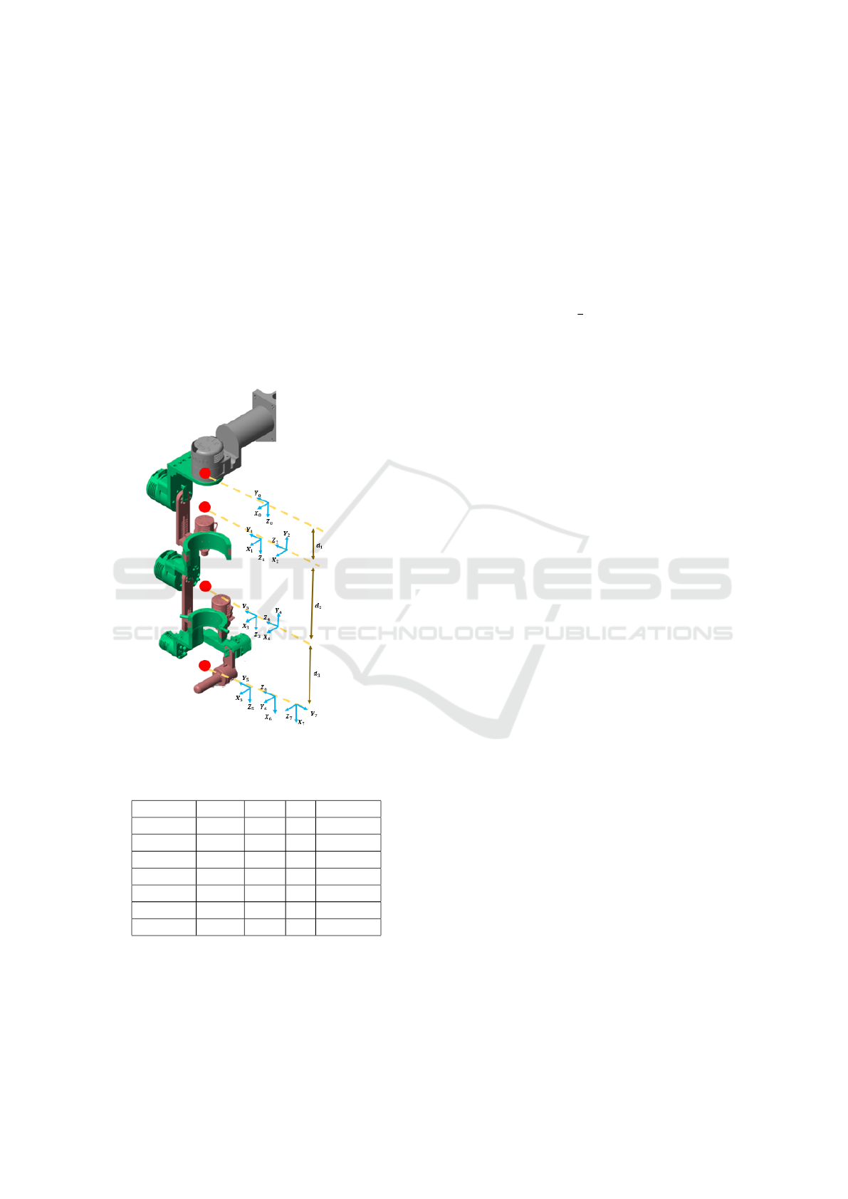
ous works (Brahmi et al., 2024). Fig. 1 illustrates
the frame assignments of the robot, and the modified
Denavit-Hartenberg parameters are listed in Table 1.
Figure 1: ETS-MARSE exoskeleton robot.
Table 1: ETS-MARSE Denavit-Hartenberg Modified Pa-
rameters.
Joint (i) α
i−1
a
i−1
d
i
q
i
1 0
◦
0 d
1
q
1
2 −90
◦
0 0 q
2
3 90
◦
0 d
3
q
3
4 −90
◦
0 0 q
4
5 90
◦
0 d
5
q
5
6 −90
◦
0 0 q
6
− 90
◦
7 −90
◦
0 0 q
7
The dynamic model of the serial robot manipula-
tor is developed using the Lagrange-Euler approach
as detailed below:
M(q) ¨q +C(q, ˙q) ˙q + G(q) = U − J
T
e
F
e
(1)
In this context, M(q) ∈ R
n×n
denotes the inertia ma-
trix, while C(q, ˙q) ∈ R
n×n
and G(q) ∈ R
n
signify the
Coriolis and centrifugal forces, as well as the gravita-
tional vector, respectively. Furthermore, U ∈ R
n
rep-
resents the control input torque, J
e
∈ R
n×n
pertains to
the end-effector Jacobian matrix, and F
e
indicates the
interaction force at the end-effector of the robot. The
dynamic characteristics of the robot (1) are defined by
the following properties:
Property 1. (Siciliano and Khatib, 2016) ∀ q, ˙q, x ∈
R
n
, it follows that x
T
(
1
2
˙
M(q) − C(q, ˙q))x = 0, and
equivalently, we have
˙
M(q) − 2C(q, ˙q) = 0.
Property 2. (Siciliano and Khatib, 2016) ∀ q, x, y ∈
R
n
we have:
C(q, x)y = C(q, y)x (2)
Property 3. (Siciliano and Khatib, 2016) For robots
that are equipped only with revolute joints, there ex-
ists a constant K
C
> 0 that fulfills the following in-
equality:
∥C(q, ˙q)∥ ≤ K
C
∥ ˙q∥ (3)
∀ q, ˙q ∈ R
n
.
Assumption 1. For Observer design, we support that
∥ ˙q∥ ≤ K
q
for any t ≥ 0 when K
q
> 0
2.1 Admittance-Based Control
To enable the robot to respond to forces exerted by the
user, an admittance control strategy is employed. This
approach interprets external forces as motion com-
mands, allowing for intuitive and compliant interac-
tion between the user and the robotic system. Con-
ceptually, the admittance function serves as a dynamic
mapping from force input to motion output and is
mathematically represented as:
q
d
= q + K
−1
3
J
T
e
ˆ
F
e
(4)
In this formulation, q
d
∈ R
n
denotes the updated de-
sired joint trajectory generated by the admittance con-
troller. The term K
3
∈ R
7×7
is a positive-definite gain
matrix that acts as a virtual stiffness, analogous to a
spring constant in mechanical systems. The vector
ˆ
F
e
∈ R
6
represents the estimated external force ap-
plied by the user, and J
T
e
is the transpose of the Ja-
cobian matrix, projecting the external force into the
joint space. This control law effectively models a
virtual spring-damper system: when the user applies
a force, the robot responds by adjusting its position
proportionally. Conversely, when the user ceases to
exert force (i.e.,
ˆ
F
e
→ 0), the influence of the admit-
tance term diminishes, causing q
d
→ q and the robot
Sensorless Admittance Control of a Manipulator Arm Using a Nonlinear Observer for Force and Velocity Estimation
17
to stabilize at its last position. This mechanism guar-
antees that the robot effectively follows the user’s in-
tended movements with compliance, while the under-
lying trajectory control manages tasks such as grav-
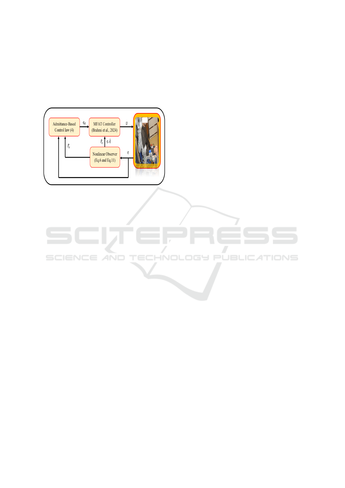
ity compensation. The block diagram of the proposed
control scheme is shown in Fig. 2. The estimation
method
ˆ
F
e
will be elaborated upon in the next section.
Figure 2: Block diagram of the admittance-based control.
3 NONLINEAR OBSERVER
DESIGN
The state representation of the dynamic model (1) is
established by defining the states as: ξ
1
= q, and ξ
2
=
˙q, leading to the following state representation:
(
˙
ξ
1
= ξ
2
˙
ξ
2
= M
−1
(ξ
1
)
h
U −J
T
e
(ξ
1
)F
e
−C(ξ
1
,
˙
ξ
1
)
˙
ξ
1
− G(ξ
1
)
i
(5)
From this representation (5), we can develop the
nonlinear observer without the need for the force vec-
tor, as outlined below:
˙
ˆ
ξ
1
=
ˆ
ξ
2
+ K
1
˜
ξ
1
˙
ˆ
ξ
2
= M
−1
(ξ
1
)
h
U −C(ξ
1
,
˙
ˆ
ξ
1
)
˙
ˆ
ξ
1
− G(ξ
1
) + K
2
˜
ξ
1
i
˜
ξ
1
= ξ
1
−
ˆ
ξ
1
= ξ
1
− q
(6)
where K
1
and K
2
represent diagonal positive definite
gain matrices. Based on ( (6)), the estimation error
can be expressed in the following state representation:
˙
˜
ξ
1
=
˜
ξ
2
− K
1
˜
ξ
1
˙
˜
ξ
2
= M
−1
(ξ
1
)
h
− J
T
e
(ξ
1
)F
e
−C(ξ
1
,
˙
ξ
1
)
˙
˜
ξ
1
−C(ξ
1
,
˙
ˆ
ξ
1
)
˙
˜
ξ
1
− K
2
˜
ξ
1
i
(7)
By differentiating
˜
ξ
1
and substituting
˙
˜
ξ
2
from
Eq. (7), the dynamics of
˜
ξ
1
is given by:
¨
˜
ξ
1
=
˙
˜
ξ
2
− K
1
˙
˜
ξ
1
= M
−1
(ξ
1
)
h
− J
T
e
(ξ
1
)F
e
−C(ξ
1
,
˙
ξ
1
)
˙
˜
ξ
1
−C(ξ
1
,
˙
ˆ
ξ
1
)
˙
˜
ξ
1
− K
2
˜
ξ
1
i
− K
1
˙
˜
ξ
1
(8)
The external torque applied to the robot model (1)
can be estimated by:
J
T
e
(ξ
1
)F
e
= − M(ξ
1
)
¨
˜
ξ
1
−
h
C(ξ
1
,
˙
ξ
1
) +C(ξ
1
,
˙
ˆ
ξ
1
)
− M(ξ1)K
1
i
˙
˜
ξ
1
− K
2
˜
ξ
1
(9)
To reduce the computational burden associated
with (9), earlier research (Alcocer et al., 2003) has
shown that a close approximation of the external force
F
e
can be achieved by concentrating solely on its final
right-hand term. Assuming that environmental forces
change gradually, we can express the estimated value
ˆ
F
e
as:
J
T
e
(ξ
1
)
ˆ
F
e
= −K
2
˜
ξ
1
(10)
By multiplying both sides of (10) by J
−T
e
(ξ
1
) and tak-
ing K
2
= K
T
2
into account, we derive the following
result:
ˆ
F
e
= −J
−1
e
(ξ
1
)K
2
˜
ξ
1
(11)
3.1 Stability Analysis
The differentiation of the first equation of (6) leads to:
¨
ˆ
ξ
1
=
˙
ˆ
ξ
2
+ K
1
˙
˜
ξ
1
(12)
By substituting
˙
ˆ
ξ
2
by its value from (6) the dynamic
of
¨
ˆ
ξ
1
is given by the following state representation:
¨
ˆ
ξ
1
= M
−1
(ξ
1
)
h
U −C(ξ
1
,
˙
ˆ
ξ
1
)
˙
ˆ
ξ
1
− G(ξ
1
) + K
2
˜
ξ
1
i
+ K
1
˙
˜
ξ
1
(13)
Multiplying both side of (13) by M(ξ
1
) we get:
M(ξ
1
)
¨
ˆ
ξ
1
=
h
U −C(ξ
1
,
˙
ˆ
ξ
1
)
˙
ˆ
ξ
1
− G(ξ
1
) + K
2
˜
ξ
1
i
+ K
1
M(ξ
1
)
˙
˜
ξ
1
(14)
Then:
M(ξ
1
)
¨
ˆ
ξ
1
+C(ξ
1
,
˙
ˆ
ξ
1
)
˙
ˆ
ξ
1
+ G(ξ
1
) = U +K
2
˜
ξ
1
+ K
1
M(ξ
1
)
˙
˜
ξ
1
(15)
ICINCO 2025 - 22nd International Conference on Informatics in Control, Automation and Robotics
18

The error dynamics is obtained by subtracting (15)
from (1)
M(ξ
1
)(
¨
ξ
1
−
¨
ˆ
ξ
1
) +C(ξ
1
,
˙
ξ
1
)
˙
ξ
1
−C(ξ
1
,
˙
ˆ
ξ
1
)
˙
ˆ
ξ
1
= −J
T
e
F
e
−K
2
˜
ξ
1
− K
1
M(ξ
1
)
˙
˜
ξ
1
M(ξ
1
)
¨
˜
ξ
1
+C(ξ
1
,
˙
ξ
1
)
˙
ξ
1
−C(ξ
1
,
˙
ˆ
ξ
1
)
˙
ˆ
ξ
1
= −J
T
e
F
e
−K
2
˜
ξ
1
− K
1
M(ξ
1
)
˙
˜
ξ
1
(16)
Based on (2) and utilizing the last equation of (6),
we can conclude:
C(ξ
1
,
˙
ξ
1
)
˙
ξ
1
−C(ξ
1
,
˙
ˆ
ξ
1
)
˙
ˆ
ξ
1
= C(ξ
1
,
˙
ξ
1
)
˙
˜
ξ
1
+C(ξ
1
,
˙
ˆ
ξ
1
)
˙
˜
ξ
1
(17)
By substituting (17) into (16) we obtain:
M(ξ
1
)
¨
˜
ξ
1
+C(ξ
1
,
˙
ξ
1
)
˙
˜
ξ
1
= −J
T
e
F
e
− K
2
˜
ξ
1
−K
1
M(ξ
1
)
˙
˜
ξ
1
−C(ξ
1
,
˙
ˆ
ξ
1
)
˙
˜
ξ
1
(18)
Theorem 1. According to Assumption (1), if:
K
1
>
K
C
K
q
M
then the equilibrium point
˙
˜
ξ
1
for (16) is asymptoti-
cally stable. The region of attraction is defined by
O
˙
˜
ξ
1
=
˙
˜
ξ
1
∈ R
n
: ∥
˙
˜
ξ
1
∥ <
r
M
min
M
max
K
1
M
K
C
− K
q
(19)
In this framework, M
min
, M
max
denotes the small-
est and largest eigenvalues of M, respectively.
Proof: Next, we will analyze the following Lya-
punov function:
V =
1
2
˙
˜
ξ
T
1
M(ξ
1
)
˙
˜
ξ
1
(20)
The time derivative of (20) yields the following:
˙
V =
˙
˜
ξ
T
1
M(ξ
1
)
¨
ξ
1
+
1
2
˙
˜
ξ
T
1
˙
M(ξ
1
)
˙
˜
ξ
1
(21)
By substituting M(ξ
1
)
¨
ξ
1
from (18) into (21), we
obtain:
˙
V =
˙
˜
ξ
T
1
− J
T
e
F
e
− K
2
˜
ξ
1
− K
1
M(ξ
1
)
˙
˜
ξ
1
−C(ξ
1
,
˙
ˆ
ξ
1
)
˙
˜
ξ
1
−C(ξ
1
,
˙
ξ
1
)
˙
˜
ξ
1
+
1
2
˙
˜
ξ
T
1
˙
M(ξ
1
)
˙
˜
ξ
1
=
˙
˜
ξ
T
1
− J
T
e
F
e
− K
2
˜
ξ
1
− K
1
M(ξ
1
)
˙
˜
ξ
1
−C(ξ
1
,
˙
ˆ
ξ
1
)
˙
˜
ξ
1
+
˙
˜
ξ
T
1
1
2
˙
M(ξ
1
)
˙
˜
ξ
1
−C(ξ
1
,
˙
ξ
1
)
˙
˜
ξ
1
(22)
By applying Property (1), we can then derive:
˙
V = −
˙
˜
ξ
T
1
(J
T
e
F
e
+ K
2
˜
ξ
1
) −
˙
˜
ξ
T
1
K
1
M(ξ
1
)
˙
˜
ξ
1
−
˙
˜
ξ
T
1
C(ξ
1
,
˙
ˆ
ξ
1
)
˙
˜
ξ
1
(23)
Considering the properties described in (2) and
(3), along with the premise presented in Assumption
(1):
˙
˜
ξ
T
C(ξ,
˙
ˆ
ξ)
˙
˜
ξ
=
−
˙
˙
ξ
T
C(ξ,
˙
ξ)
˙
˜
ξ +
˙
˙
ξ
T
C(ξ,
˙
ξ)
˙
˜
ξ
≤ ∥
˙
˜
ξ∥
2
K
C
∥
˙
˜
ξ∥ + K
q
(24)
From (10), we obtain J
T
e
F
e
= −K
2
˜
ξ
1
. As a result,
(23) is transformed as :
˙
V ≤ −∥
˙
˜
ξ∥
2
h
K
1
M(ξ
1
) − K
C
∥
˙
˜
ξ∥ + K
q
i
(25)
Hence, if
∥
˙
˜
ξ∥ <
K
1
M
K
C
− K
q
(26)
where M(ξ
1
) = M Then ,
˙
V ≤ −κ∥
˙
˜
ξ∥
2
(27)
where κ > 0, the right side of (26) is positive by hy-
pothesis. Furthermore,
1
2
M
min
∥
˙
˜
ξ∥
2
≤ V (
˙
˜
ξ) ≤
1
2
M
max
∥
˙
˜
ξ∥
2
(28)
It is clear that V (
˙
˜
ξ) is a positive definite and de-
creasing function defined on (28). Since
˙
V (
˙
˜
ξ) ≤ 0, ∀
˙
˜
ξ
satisfies the conditions outlined in (26), we can infer
that the equilibrium point
˙
˜
ξ = 0 is uniformly stable,
as shown in (Hahn et al., 1967).
To illustrate this attractive feature, by
∥
˙
˜
ξ(0)∥ <
r
M
min
M
max
K
1
M
K
C
− K
q
(29)
Then,
V (
˙
˜
ξ) ≤ V (
˙
˜
ξ(0))
˙
V (
˙
˜
ξ) ≤ −κ∥
˙
˜
ξ∥
2
(30)
The inequality (30) ensures that
˙
˜
ξ remains
bounded. Since
˙
ξ and
¨
˜
ξ are confirmed to be bounded
Sensorless Admittance Control of a Manipulator Arm Using a Nonlinear Observer for Force and Velocity Estimation
19
in (16) it follows that
˙
˜
ξ is uniformly continuous. Ad-
ditionally, from (30), we conclude:
κ
Z
∞
0
∥
˙
˜
ξ∥
2
dt ≤ −
Z
∞
0
˙
V (t)dt = V (0) −V (∞) < ∞
(31)
and therefore:
lim
t→∞
∥
˙
˜
ξ∥ = 0 (32)
which, when substituted into (16) yields:
lim
t→∞
∥
˜
ξ∥ = 0 (33)
Discussion: The convergence of the observer
is guaranteed provided that the joint velocities are
bounded and the initial estimation error lies within
an appropriate region of attraction. However, this re-
quirement on velocity bounds becomes unnecessary
when the observer is integrated with a (MFAT) con-
trol law. The extent of the region of attraction can
be increased by tuning the observer gain constant K
1
.
Since the joint positions are assumed to be measur-
able, the observer can be initialized with
ˆ
ξ(0) = ξ(0),
ensuring that only the initial error in the velocity esti-
mate,
˙
˜
ξ(0), needs to satisfy condition (19).
4 EXPERIMENTAL VALIDATION
The proposed approach is experimentally validated
using the ETS-MARSE system, which is set up with
a National Instruments NI PXI-1031 chassis. This
hardware configuration consists of two key compo-
nents: an FPGA card (NI PXI-7813R) and a dual-
core controller card (NI PXI-8108). The Intel Core
2 Duo-based controller operates at 200 Hz, execut-
ing the outer loop of the proposed algorithm while
concurrently processing joint position feedback from
Hall-effect sensors. Meanwhile, the FPGA card op-
erates at a significantly higher frequency of 20 kHz
to ensure accurate real-time execution of the inner-
loop PI current control. The torque commands sent to
the exoskeleton arm are generated via LabVIEW soft-
ware running on a connected host computer (Brahmi
et al., 2024; Brahmi et al., 2019). The chosen val-
ues for the designed observer gains are provided in
Table 2.
In this test, the subject wears the robotic device
and moves it away from the initial position with the
elbow flexed at 90
◦
. The desired trajectory is gener-
ated using the admittance control law (4). Through-
out the experiment, the force applied by the subject is
recorded by the force sensor and compared with the
estimated force derived from (11). This section aims
to evaluate the effectiveness of the proposed nonlin-
ear observer in delivering precise force and velocity
estimates for admittance-based control. The experi-
mental findings are summarized in Figs. 3–7.
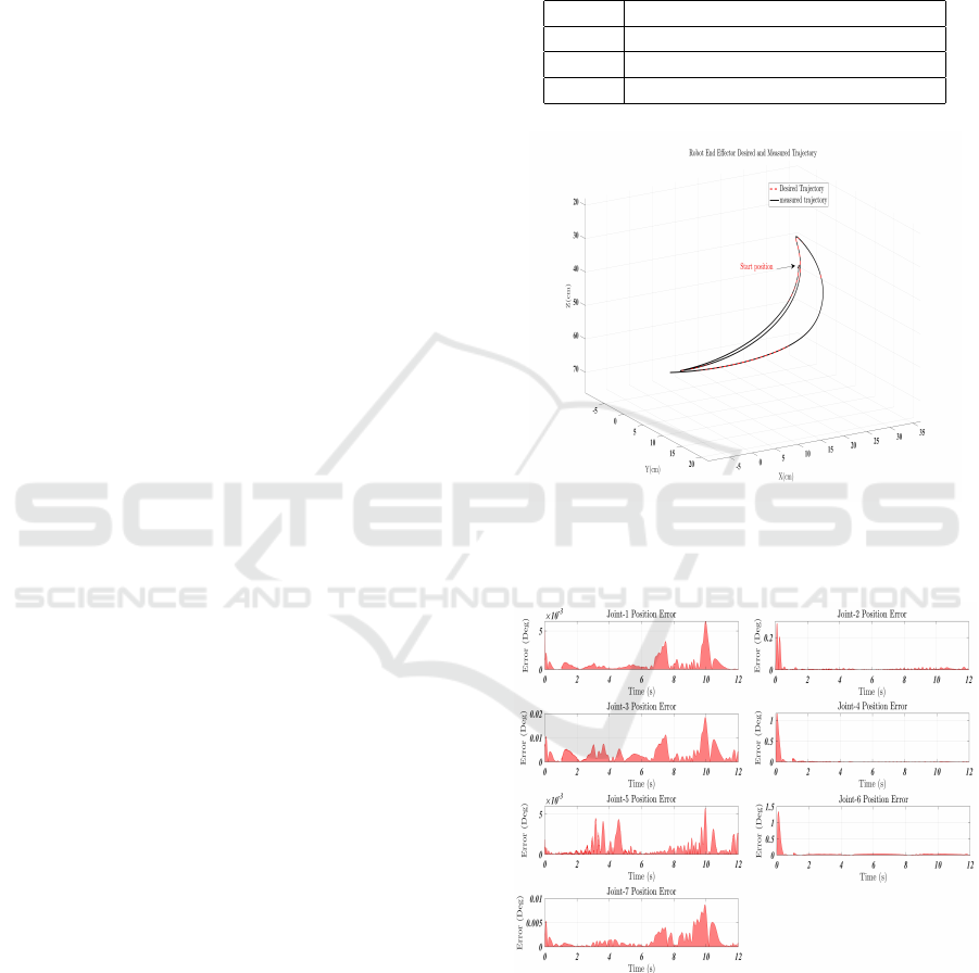
Table 2: Proposed observer gains.
Gains Value
K
1
diag[15, 15, 15, 15, 15, 15, 15]
K
2
diag[50, 50, 50, 50, 50, 50, 50]
K
3
diag[1.1, 1.1, 1.1, 1.1, 1.1, 1.1, 1.1]
Figure 3: The Cartesian performance of ETS-MARSE in
3D space: the desired trajectory (black line ) and the mea-
sured trajectory (dashed red line).
Figure 4: Joint position Tracking Error Over Time.
Fig. 3 illustrates the 3D Cartesian performance of
the ETS-MARSE system. The measured trajectory,
shown as a dashed red line, closely follows the desired
trajectory represented by the solid black line. This
indicates that the admittance controller, driven by
observer-estimated forces, effectively translates user-
applied inputs into compliant spatial motion. Further-
ICINCO 2025 - 22nd International Conference on Informatics in Control, Automation and Robotics
20
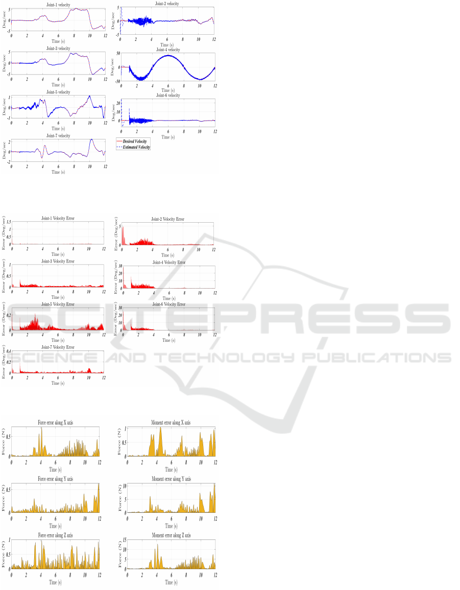
Figure 5: Joint velocity tracking: the desired trajectory (red
solid line ) and the estimated velocity (dashed blue line).
Figure 6: Joint Velocity Tracking Error Over Time.
Figure 7: Tracking error between estimated force and mea-
sured force provided sensor.
more, the robot’s high performance is attributed to
the robust adaptive control implemented in this study
(Brahmi et al., 2024), which effectively accommo-
dates dynamic variations and uncertainties in human-
robot interactions. Fig. 4 presents the joint position
tracking error over time, where errors remain minimal
and stable across all joints. The stability and accuracy
of the admittance control loop further reinforce the re-
liability of the observer in consistently providing state
information necessary for position regulation. Fig. 5
compares the estimated joint velocities (dashed blue
line) with the desired velocity profile (solid red line).
The close correspondence between these two curves
reflects the observer’s capability to reconstruct joint
velocities without requiring direct velocity sensing,
even during dynamic transitions. Fig. 6 quantifies the
joint velocity estimation error, which remains small
and bounded throughout the task duration. This out-
come supports the observer’s applicability for real-
time control applications where velocity feedback is
typically absent or unreliable. Fig. 7 compares the
estimated interaction force against the ground-truth
measurements from the force sensor. The estimated
force closely follows the measured values, exhibit-
ing only minor discrepancies during high-dynamic
phases.
5 CONCLUSIONS
This paper introduces a nonlinear observer-based
technique for estimating force and velocity in a joint-
space admittance-controlled exoskeleton. The system
aims to promote safe and compliant interactions be-
tween humans and robots. A thorough stability anal-
ysis is performed using Lyapunov theory to confirm
the asymptotic stability of the estimated states. The
proposed nonlinear observer effectively estimates ex-
ternal forces and joint velocities by relying solely on
joint position feedback. This ability facilitates sensor-
less admittance control in the ETS-MARSE exoskele-
ton. Experimental results validate the accuracy and
robustness of the method, revealing low tracking er-
rors and high compliance with human-intended move-
ments. Consequently, this approach eliminates the
need for delicate and costly force sensors while en-
suring safe and transparent interactions. Future work
will focus on testing with a broader population to as-
sess generalizability across different biomechanical
profiles. Additionally, we will investigate adaptive
observer tuning and the integration of biosignal inter-
faces (such as EMG) to enhance responsiveness. Our
efforts will also prioritize real-world deployment sce-
narios, including autonomous rehabilitation sessions
Sensorless Admittance Control of a Manipulator Arm Using a Nonlinear Observer for Force and Velocity Estimation
21

and tele-operated assistive systems.
ACKNOWLEDGEMENTS
This work was supported by the Center for Interdis-
ciplinary Research on Intelligent Manufacturing and
Robotics at King Fahd University of Petroleum &
Minerals, Dhahran, Saudi Arabia, under the research
grant INMR2508, titled ”Adaptive Learning Control
Design for Safe and Efficient Human-Robot Collabo-
ration in Dynamic Industrial Environments”.
REFERENCES
Alcocer, A., Robertsson, A., Valera, A., and Johansson, R.
(2003). Force estimation and control in robot ma-
nipulators. In Robot Control 2003 (SYROCO’03): A
Proceedings Volume from the 7th IFAC Symposium,
page 55, Wrocław, Poland.
Brahmi, B., Dahani, H., Bououden, S., Fareh, R., and Rah-
man, M. H. (2024). Adaptive-robust controller for
smart exoskeleton robot. Sensors, 24(2):489.
Brahmi, B., Laraki, M. H., Saad, M., Rahman, M. H.,
Ochoa-Luna, C., and Brahmi, A. (2019). Compli-
ant adaptive control of human upper-limb exoskeleton
robot with unknown dynamics based on a modified
function approximation technique (mfat). Robotics
and Autonomous Systems, 117:92–102.
Brahmi, B. and Saad, M. (2023). Adaptive control of an
electrically driven exoskeleton robot (theory and ex-
periments). Journal of Vibration Engineering & Tech-
nologies, 11(7):3399–3412.
Chen, W.-H., Ballance, D. J., Gawthrop, P. J., and O’Reilly,
J. (2000). A nonlinear disturbance observer for robotic
manipulators. IEEE Transactions on Industrial Elec-
tronics, 47:932–938.
Chen, X., Wang, N., Cheng, H., and Yang, C. (2020). Neu-
ral learning enhanced variable admittance control for
human–robot collaboration. IEEE Access, 8:25727–
25737.
Culmer, P. R., Jackson, A. E., Makower, S., et al. (2010). A
control strategy for upper limb robotic rehabilitation
with a dual robot system. IEEE/ASME Transactions
on Mechatronics, 15:575–585.
Gupta, A. and O’Malley, M. K. (2011). Disturbance-
observer-based force estimation for haptic feedback.
Journal of Dynamic Systems, Measurement, and Con-
trol, 133:014505.
Hahn, W. et al. (1967). Stability of motion, volume 138.
Springer.
Hogan, N. (1985). Impedance control: An approach to ma-
nipulation—part i: Theory; part ii: Implementation;
part iii: Applications. ASME Journal of Dynamic Sys-
tems, Measurement, and Control, 107(1):1–24.
Hongli, C. (2022). Design of a fuzzy fractional order adap-
tive impedance controller with integer order approxi-
mation for stable robotic contact force tracking in un-
certain environment. Acta Mechanica et Automatica,
16(1):16–26.
Hsu, H.-H., Lee, W.-K., and Lee, P.-L. (2025). Designing
an eeg signal-driven dual-path fuzzy neural network-
controlled pneumatic exoskeleton for upper limb re-
habilitation. International Journal of Fuzzy Systems,
pages 1–19.
Ibarguren, A., Daelman, P., and Prada, M. (2020). Con-
trol strategies for dual arm co-manipulation of flexi-
ble objects in industrial environments. In Proc. IEEE
Conf. Ind. Cyberphysical Syst., pages 514–519, Tam-
pere, Finland.
Iqbal, K. and Zheng, Y. F. (1999). Arm-manipulator coor-
dination for load sharing using predictive control. In
Proceedings of the IEEE International Conference on
Robotics and Automation (ICRA), pages 2539–2544.
Jaroonsorn, P. et al. (2020). Robot-assisted transcranial
magnetic stimulation using hybrid position/force con-
trol. Advanced Robotics, 34(24):1559–1570.
Jung, S. and Hsia, T. C. (2000). Robust neural force control
scheme under uncertainties in robot dynamics and un-
known environment. IEEE Transactions on Industrial
Electronics, 47(2):403–412.
Karimi, M. and Ahmadi, M. (2025). ilead: An emg-based
adaptive shared control framework for exoskeleton as-
sistance via deep reinforcement learning. IEEE Trans-
actions on Artificial Intelligence.
Katsura, S., Matsumoto, Y., and Ohnishi, K. (2007). Mod-
eling of force sensing and validation of disturbance
observer for force control. IEEE Transactions on In-
dustrial Electronics, 54(1):530–538.
Li, M., Wen, Y., Gao, X., Si, J., and Huang, H. (2022a). To-
ward expedited impedance tuning of a robotic prosthe-
sis for personalized gait assistance by reinforcement
learning control. IEEE Transactions on Robotics,
38(1):407–420.
Li, Z., Li, X., Li, Q., Su, H., Kan, Z., and He, W.
(2022b). Human-in-the-loop control of soft exosuits
using impedance learning on different terrains. IEEE
Transactions on Robotics, 38(5):2979–2993.
Lynch, K. M., Liu, C., Sorensen, A., Kim, S., Peshkin, M.,
Colgate, J. E., Tickel, T., Hannon, D., and Shiels, K.
(2002). Motion guides for assisted manipulation. In-
ternational Journal of Robotics Research, 21(1):27–
43.
Miller, L. M. and Rosen, J. (2010). Comparison of multi-
sensor admittance control in joint space and task space
for a seven degree of freedom upper limb exoskeleton.
In 2010 3rd IEEE RAS and EMBS International Con-
ference on Biomedical Robotics and Biomechatronics
(BioRob), pages 70–75, Tokyo, Japan.
Newman, W. S. (1992). Stability and performance limits
of interaction controllers. ASME Journal of Dynamic
Systems, Measurement, and Control, 114:563–570.
Otten, A., Voort, C., Stienen, A., Aarts, R., van Asseldonk,
E., and van der Kooij, H. (2015). Limpact: A hydrauli-
cally powered self-aligning upper limb exoskeleton.
ICINCO 2025 - 22nd International Conference on Informatics in Control, Automation and Robotics
22

IEEE/ASME Transactions on Mechatronics, 20:2285–
2298.
Ozkul, F. and Barkana, D. E. (2013). Upper-extremity reha-
bilitation robot rehabroby: Methodology, design, us-
ability and validation. International Journal of Ad-
vanced Robotic Systems, 10:1–13.
Popescu, N., Popescu, D., Ivanescu, M., Popescu, D.,
Vladu, C., and Vladu, I. (2013). Force observer-based
control for a rehabilitation hand exoskeleton system.
In 2013 9th Asian Control Conference (ASCC), pages
1–6.
Qin, X. et al. (2021). The adaptive neural network sliding
mode control for angle/force tracking of the dexterous
hand. Advances in Mechanical Engineering, 13.
Siciliano, B. and Khatib, O. (2016). Robotics and the hand-
book. In Springer Handbook of Robotics, pages 1–6.
Springer.
Siciliano, B. and Villani, L. (2000). Robot Force Control.
Springer, Berlin, Germany.
Xue, T., Wang, W., Ma, J., Liu, W., Pan, Z., and Han, M.
(2020). Progress and prospects of multimodal fusion
methods in physical human–robot interaction: A re-
view. IEEE Sensors Journal, 20(18):10355–10370.
Zarrin, R. S., Zeiaee, A., and Langari, R. (2024).
A variable-admittance assist-as-needed controller
for upper-limb rehabilitation exoskeletons. IEEE
Robotics and Automation Letters.
Zhang, Z. (2021). A computational framework for robot
hand design via reinforcement learning. In Proceed-
ings of the IEEE/RSJ International Conference on
Intelligent Robots and Systems (IROS), pages 7216–
7222, Prague, Czech Republic.
Sensorless Admittance Control of a Manipulator Arm Using a Nonlinear Observer for Force and Velocity Estimation
23
