
Artificial Neural Network-Based MPPT Controller for PV System
Integrated with Grid and Induction Motor
Priyanka Nikhil Mane, Rushikesh Sunil Suryawanshi, Neel Ajit Mangave,
Harshal Anandrao Nalawade and Ayan Firoj Sayyad
Department of Electrical Engineering, Kolhapur Institute of Technology's College of Engineering (Empowered
Autonomous), Kolhapur, India
Keywords: PV, ANN Based MPPT, VSI, PI, LC Filter, SVPWM.
Abstract: The integration of a Photovoltaic (PV) system with an induction motor and grid offers a sustainable solution
for energy generation and utilization, particularly in industrial and commercial applications. However, to
guarantee effective functioning, it is essential to optimize the power extracted from PV system. The PV
system's operating point, which fluctuates with external conditions including temperature and sun irradiation,
must be dynamically adjusted by a Maximum Power Point Tracking (MPPT) controller in order to capture
maximum amount of power. Traditional MPPT algorithms, while effective, may not always provide optimal
performance in fluctuating conditions. To address this, an Artificial Neural Network (ANN) based MPPT
controller enhance the tracking accuracy and efficiency. By learning from system behavior and adjusting in
real-time, the ANN-based controller outperforms conventional methods, offering superior performance and
faster convergence to Maximum Power Point (MPP). When integrated with the grid and an induction motor,
this intelligent MPPT controller ensures not only optimal energy extraction from the PV system but also stable
power delivery. The induction motor, driven by solar energy, operates efficiently with minimal energy losses,
while the grid connection facilitates the exchange of power, ensuring system stability. Simulation results are
obtained using MATLAB, showing that efficiency of the tracking method is 93.5% and the THD value of 2%.
1 INTRODUCTION
In recent years, induction motors have become
indispensable in various industries, serving as the
backbone for many essential operations. Induction
motors account for over 40% of global electric power
consumption, reflecting their widespread usage.
These motors are used to drive machinery in sectors
such as manufacturing, water pumping, HVAC
systems, and various types of compressors. Their
widespread application is primarily due to their
versatility, durability, and cost-effectiveness, making
them the preferred choice for industrial operations
that require reliable, continuous power. However, as
society progresses and the demand for electric motors
continues to rise, so does the need for more electrical
energy. This surge in demand has put significant
pressure on existing power generation systems,
exacerbating the strain on traditional energy sources.
Fossil fuels, the primary source of energy in many
parts of world, are becoming less sustainable due to
the increasing environmental concerns they generate.
The emission of greenhouse gases and depletion of
non-renewable resources have led to mounting
restrictions on expanding fossil fuel-based energy
sources.
To combat these issues and meet growing demand
for energy, Renewable Energy Systems (RES),
especially solar power, are being increasingly
embraced. Solar energy, captured through PV
systems, offers a clean, sustainable and abundant
energy source. The integration of RES with
technologies such as induction motors presents an
opportunity for industries to operate in a more
energy-efficient and environmentally friendly
manner. By utilizing solar energy to power induction
motors, industries reduce their reliance on
conventional, polluting energy sources and decrease
their carbon footprint. This integration not only
addresses the global energy demand but also
promotes a greener, more sustainable future by
mitigating the environmental impacts of traditional
Mane, P. N., Suryawanshi, R. S., Mangave, N. A., Nalawade, H. A. and Sayyad, A. F.
Artificial Neural Network-Based MPPT Controller for PV System Integrated with Grid and Induction Motor.
DOI: 10.5220/0013642900004664
Paper published under CC license (CC BY-NC-ND 4.0)
In Proceedings of the 3rd International Conference on Futuristic Technology (INCOFT 2025) - Volume 3, pages 721-732
ISBN: 978-989-758-763-4
Proceedings Copyright © 2025 by SCITEPRESS – Science and Technology Publications, Lda.
721
energy production. The voltage from the PV system
is increased using a boost converter.
Tracking mechanisms such as Hill Climbing
(Moll and Linda, 2023 – Glowed and Masoud, 2020),
Incremental Conductance (IncCond) (Karan, Bashar,
et al. 2022), and Perturb and Observe (P&O)
(Mohammad, 2024) play a vital role in accurately
measuring the power extracted from PV systems.
Among these, P&O method is known for its high
accuracy and adaptability, however it is sensitive to
variations in solar irradiance, temperature, and panel
orientation. IncCond enhances efficiency and reduces
oscillations, providing more stable tracking
nevertheless it faces challenges in terms of space,
weight, and maintenance. Hill Climbing offers
reliable tracking and flexibility in system
configurations, however it requires significant
computational resources. To address these
limitations, this work proposes the implementation of
an ANN-based MPPT technique, which improves
energy efficiency, ensures precise tracking of the
optimal power from PV systems, and offers
exceptional adaptability for a range of solar power
applications. The key contributions of this study are:
• To maximise the utilisation of renewable
energy sources and preserve grid stability, PV
systems must be integrated with the electrical
grid and BLDC motor.
• The implementation of Boost converter
boosts the low PV panel voltage, improves
efficiency and enhances the reliability of the
PV system.
• ANN based MPPT method is implemented to
track maximum power generated by PV
system.
2 PROPOSED SYSTEM
DESCRIPTION
In this work, a PV system is designed for efficient
energy conversion and seamless integration with the
grid, utilizing advanced control techniques for
optimal performance. When sunlight is converted
into Direct Current (DC) electrical energy by solar
panels, a boost converter increases voltage to
appropriate level for further processing. Using an
MPPT algorithm, which continuously modifies PV
array's operating point to collect maximum power
under changing environmental conditions, energy
extraction is maximized. The increased voltage is fed
into a Pulse-Width Modulation (PWM) generator,
which generates PWM pulses to regulate a converter's
switching function. The power is delivered to an
induction motor, with a proportional-integral (PI)
controller managing the power flow and optimizing
energy delivery while adapting to varying load
conditions. For accurate VSI control, the system
additionally uses Space Vector Pulse Width
Modulation (SVPWM), which guarantees ideal
voltage regulation and effective inverter operation.
Additionally, a three-phase voltage source inverter
(VSI) is used to send excess power from PV system
to the grid. This ensures a stable and effective
interaction between PV system and the grid by
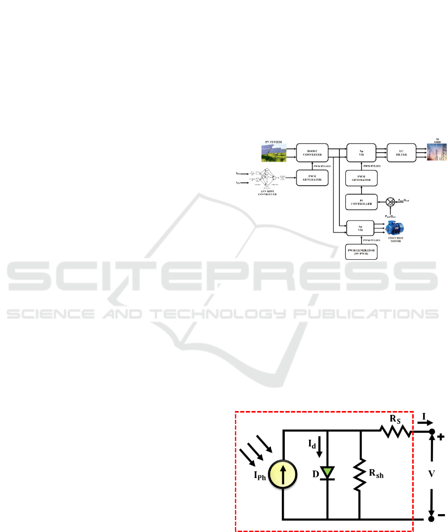
controlling the power transfer. Figure 1 displays the
proposed work's block diagram.
Figure 1: Proposed Block Diagram
3 SYSTEM MODELLING
3.1 PV System
The core part of a solar energy system, a PV cell
converts sunlight directly into electrical energy. The
electrical properties of a large diode is seen in a PV
cell.
Figure 2: PV cell
INCOFT 2025 - International Conference on Futuristic Technology
722
When exposed to light, the output current is the
sum of the dark current (𝐼
) and the photocurrent
(𝐼
), which is expressed as:
𝐼= 𝐼
− 𝐼
(1)
The equivalent circuit of PV system is shown in
Figure 2. In practical, A series resistance is used to
dissipate electricity (𝑅
) caused by ohmic contact on
the front surface, and a shunt resistance (𝑅𝑠ℎ) due to
leakage current, as depicted in Figure 2. Therefore,
the Equation 1 is written as:
𝐼= 𝐼
− 𝐼
− 𝐼
(2)
A PV system's output voltage, which is typically
low, is increased with a boost converter.
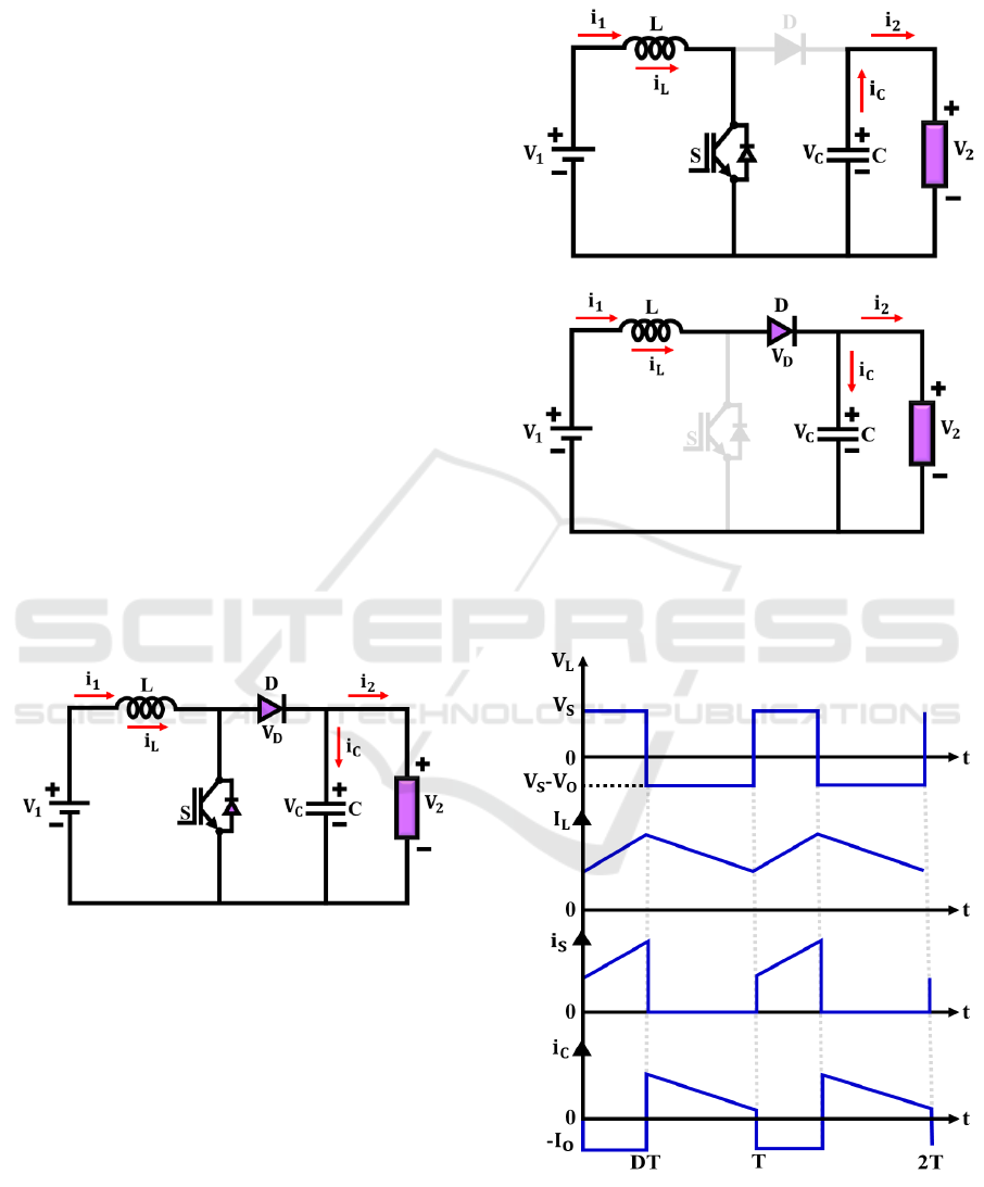
3.2 Boost Converter
A number of important parts are arranged in a specific
way in the boost converter's schematic diagram,
which is displayed in Figure 3. Notably, circuit
features parallel-connected inductors and switches,
with the inductor (𝐿) and switch (𝑆) also arranged in
parallel. Additionally, the diode (𝐷) is configured in
parallel, creating two parallel paths between the input
and output circuits. This configuration improves the
converter’s performance and reliability, making it
ideal for a range of power conversion applications.
Figure 3: Equivalent circuit of Boost converter
Mode 1: In mode 1, switch 𝑆 is in ON condition
and diode 𝐷 is in OFF condition, where the inductor
𝐿 is charging and the capacitor 𝐶 is discharging.
Mode 2: In mode 2, Diode 𝐷 is in ON condition,
and switch 𝑆 is in OFF condition, where Capacitor 𝐶
is charging and Inductor 𝐿 is discharging.
Figure 5 represents the switching waveform of the
boost converter. Boost converters often exhibit
nonlinear dynamics due to switching operations,
control loops, and varying loads. The ANN-based
MPPT controller is well-suited to model these
nonlinearities, providing a more accurate
representation of the converter’s behavior.
Additionally, the tracking of the converter’s output is
achieved using an ANN-based MPPT controller.
(a)
(b)
Figure 4: Equivalent Circuit of Boost converter (a) Mode 1,
(b) Mode 2
Figure 5: Switching Waveform
Artificial Neural Network-Based MPPT Controller for PV System Integrated with Grid and Induction Motor
723
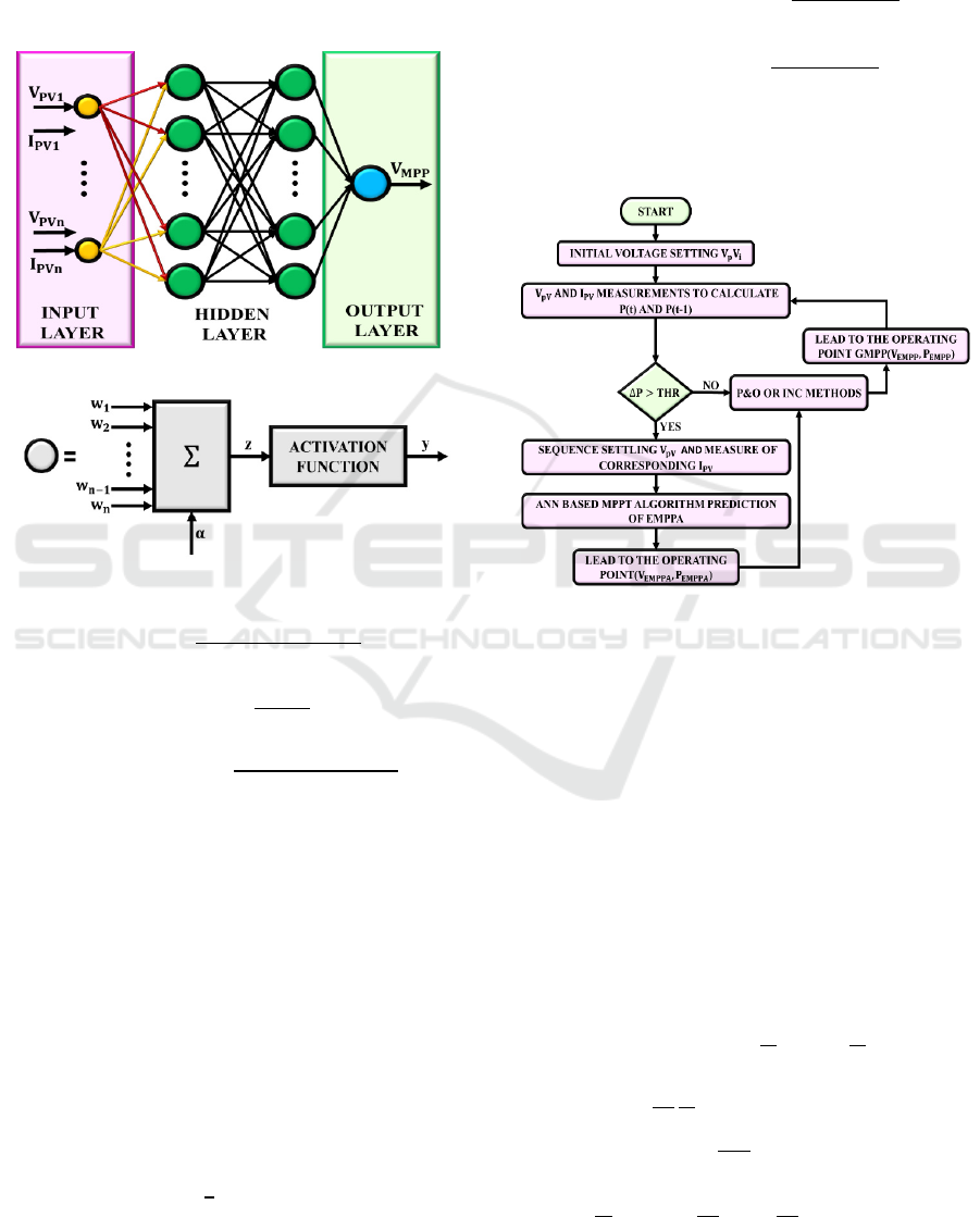
3.3 ANN based MPPT Algorithm
The ANN based MPPT algorithm uses ANN to
optimize the MPPT of PV systems. By learning
relationship between environmental factors and the
system’s output power, ANN predict and adjust the
operating point to ensure maximum power extraction.
Figure 6: Architecture of ANN based MPPT
𝑀𝑎𝑝𝑚𝑖𝑛𝑚𝑎𝑥 =
(
)(
)
(
)
+y
(3)
𝑇𝑎𝑛𝑠𝑖𝑔 =
-1 (4)
𝑀𝑎𝑝𝑚𝑖𝑛𝑚𝑎𝑥_𝑟𝑒𝑣𝑒𝑟 =
(
)(
)
(
)
+x
(5)
As shown in Equation 3, 𝑀𝑎𝑝𝑚𝑖𝑛𝑚𝑎𝑥 function
is employed to normalize input values. In the hidden
layer, the 𝑇𝑎𝑛𝑠𝑖𝑔 function, as defined in Equation 4,
serves as the activation function. The normalized
values are then reverted to their original values using
the 𝑀𝑎𝑝𝑚𝑖𝑛𝑚𝑎𝑥_𝑟𝑒𝑣𝑒𝑟 function, as indicated in
Equation 5.
𝑦
= 𝑓(∑𝑤
𝑥
+𝑏) (6)
Where 𝑥
is the input signal, 𝑤
represents the
connection weight, 𝑓 is the activation function, 𝑦
is
the output neuron and 𝑏 is the bias value.
E =
∑
(𝑦
−𝑦
)
(7)
The performance of ANN is evaluated using
regression coefficient 𝑅
. These performance metrics
are defined in Equations 8 and 9, respectively.
MSE =
∑
(
,
)
(8)
𝑅
=1−
∑
(
,
)
∑
(
,
)
(9)
Where 𝑦
,
is the estimated value, n is the sample
size,𝑦
,
is the measured value, and 𝑦
is the value of
the sampled data.
Figure 7: Flowchart of ANN based MPPT
Flowchart of ANN based MPPT algorithm is
represented in Figure 7, which enhances tracking
efficiency, reduces computation time, and improves
overall system performance.
3.4 Induction Motor
A active electric motor type in industrial settings is
the induction motor, which is dependable, long-
lasting, and requires low maintenance. It spins by
creating a revolving magnetic field that causes the
rotor to conduct current. Particularly when combined
with RES, it is essential to many energy-efficient
systems. The speed of the induction motor is
expressed as:
𝑉
= 𝑖
𝑅
+𝐿
(
𝑖
)
+
(𝜓
) (10)
𝑉
=
(
𝜓
)
+𝑅
𝜎𝐿
)𝑖
(11)
Where, 𝜎=1−
Similarly,
𝜓
=
𝜐
−
(
𝑅
+𝜎𝐿
𝑆
)
𝑖
( 12 )
INCOFT 2025 - International Conference on Futuristic Technology
724
(
𝜓
)
=
𝑖
−𝜔
𝜓
−
𝜓
(13)
(
𝜓
)
=
𝑖
+𝜔
𝜓
−
𝜓
(14)
Where, 𝑇
=
The rotor angle is estimated as follows:
𝜃
=tan
(15)
Hence, speeds of the rotor is computed by using
following equations,
𝜔
=
𝑑
𝑑𝑡
𝜃
=
𝜓
𝜓
−𝜓
𝜓
−
𝜓
𝑖
−
𝜓
𝑖
(16)
The integration of SVPWM with an induction
motor significantly enhances performance and
efficiency of system. Additionally, SVPWM helps in
reducing THD, further contributing to system’s
overall stability and performance. Thus, the
combination of SVPWM and induction motors
proves to be a highly effective resolution for
optimizing induction motor control in RES and other
power-driven applications.
4 RESULTS AND DISCUSSION
In this paper, a boost converter for a PV grid-
connected system with an ANN based MPPT
controller is presented. To assess RES based system's
performance, MATLAB simulations are performed.
These findings support the adoption of this advanced
control strategy for grid and BLDC Motor integrated
PV systems. The parameters for PV system and Boost
converter are provided in Table 1.
Table 1: The parameters for PV system and Boost converter
Parameters Rating
PV system
𝑂𝑝𝑒𝑛 𝐶𝑖𝑟𝑐𝑢𝑖𝑡 𝑉𝑜𝑙𝑡𝑎
𝑔
𝑒 37.25 𝑉
𝑆ℎ𝑜𝑟𝑡 𝐶𝑖𝑟𝑐𝑢𝑖𝑡 𝐶𝑢𝑟𝑟𝑒𝑛𝑡 8.95 𝐴
𝑆𝑒𝑟𝑖𝑒𝑠 𝐶𝑜𝑛𝑛𝑒𝑐𝑡𝑒𝑑 𝑆𝑜𝑙𝑎𝑟 𝑃𝑉 𝑐𝑒𝑙𝑙 2
𝑃𝑎𝑟𝑎𝑙𝑙𝑒𝑙 𝐶𝑜𝑛𝑛𝑒𝑐𝑡𝑒𝑑 𝑆𝑜𝑙𝑎𝑟 𝑃𝑉 𝑐𝑒𝑙𝑙 14
𝑀𝑎𝑥𝑖𝑚𝑢𝑚 𝑃𝑜𝑤𝑒𝑟 𝑣𝑜𝑙𝑡𝑎𝑔𝑒 29.95 𝑉
𝑀𝑎𝑥𝑖𝑚𝑢𝑚 𝐶𝑢𝑟𝑟𝑒𝑛𝑡 8.35 𝐴
Boost converter
L
1 𝑚𝐻
C
2200 𝜇𝐹
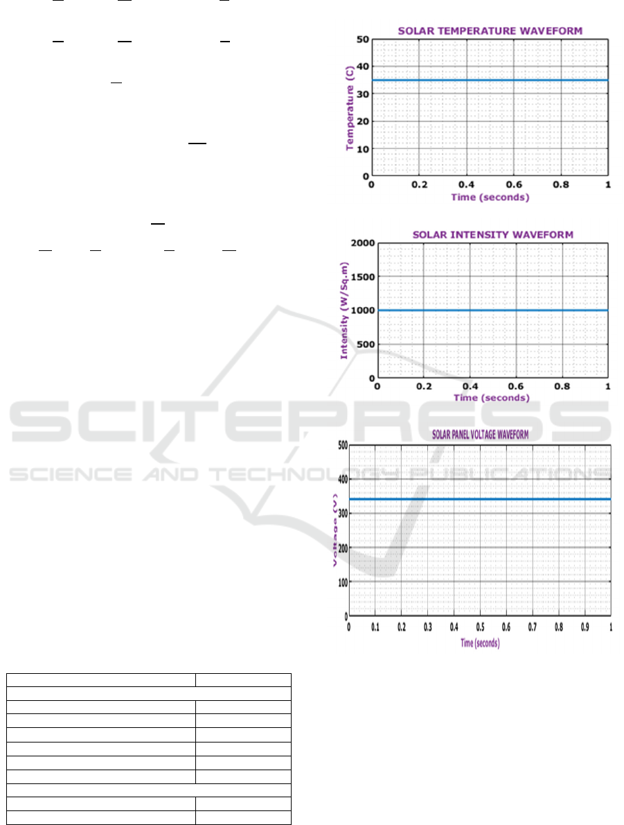
Case 1: Constant Temperature and Irradiance
(a)
(b)
(c)
Figure 8: Solar panel (a) Temperature, (b) irradiance and
(c) Voltage waveform
As shown in figure 8(a), temperature maintains
continual at 35°C. Similarly, figure 8(b) illustrates
that the irradiance remains steady at 1000 W/m²,
while figure 8(c) shows the voltage waveform
maintaining a constant 340V.
Artificial Neural Network-Based MPPT Controller for PV System Integrated with Grid and Induction Motor
725
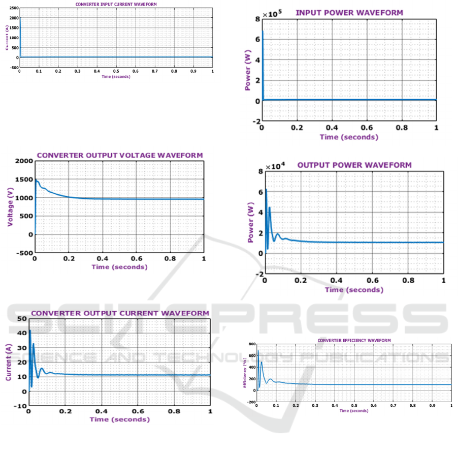
Figure 9: Converter input current waveform
The waveform of converter's input current peaks
at 10A at 0.1 seconds, presenting a significant current
flow at this time.
(a)
(b)
Figure 10: Converter output voltage and output current
waveform
The waveforms in Figure 10 illustrate converter’s
output. The converter, aided by ANN based MPPT
controller, consistently produces a stable voltage and
current. The output voltage quickly stabilizes at
1000V within just 0.1s, while the current settles at
12A within the same brief period.
Figure 11 presents the power waveforms. In
Figu
re
11(a), the input power waveform stabilizes at
10000 Watts following some initial fluctuations.
Meanwhile, Figure 11(b) depicts the output power
waveform, which reaches a peak within 0.1 seconds,
before settling at a steady 12000 Watts for a duration
of 0.05 seconds.
(a)
(b)
Figure 11: Power Waveform (a) Input and (b) Output
Figure 12: Waveform of Efficiency
The efficiency waveform in Figure 12 shows a
rapid increase within the first 0.1 seconds, followed
by stabilization around 83.3% for the remainder of the
duration. This indicates a consistent and efficient
performance of the system.
Case 2: Varying temperature and intensity
Figure 13 displays the solar panel's waveforms. A
speedy and noticeable increase is seen in Figure
13(a), where temperature begins at 25°C and climbs
to 45°C in 0.3 seconds. Figure 13(b) illustrates the
irradiance waveform, which begins at 800 W/m² and
increases to 1000 W/m² after 0.5 seconds. Finally,
Figure 13(c) depicts the voltage waveform, which
stabilizes at 340V.
INCOFT 2025 - International Conference on Futuristic Technology
726
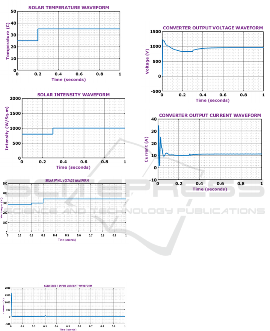
(a)
(b)
(c)
Figure 13: Solar panel waveform (a) Temperature, (b)
Irradiance and (c) Voltage waveform under varying
condition
Figure 14: Converter input current waveform
The input current waveform of the converter
reaches a peak of 10A at 0.1 seconds, indicating a
substantial current flow at this moment.
(a)
(b)
Figure 15: Converter output voltage and current waveform
The converter's output waveforms are displayed
in Figure 15. The converter keeps the voltage and
current steady with the help of ANN based MPPT
controller. The output voltage quickly reaches 900V
in 0.1 seconds, and the current reaches 11A in the
same amount of time.
Figure 16 shows power waveforms: Figure 16(a)
illustrates the input power stabilizing at 9000 Watts,
while Figure 16(b) shows the output power peaking
and settling at 110 Watts. Figure 16 (c) displays
efficiency, rising quickly to stabilize at 81.8%.
Figure 17 illustrates the voltage waveforms of
VAB, VBC, and VCA, each maintaining a consistent
voltage level of 1200V over a duration of 1 second.
These waveforms represent the balanced three-phase
voltage outputs in the system which indicates a stable
operation.
Artificial Neural Network-Based MPPT Controller for PV System Integrated with Grid and Induction Motor
727

Figure 16: Waveform (a) Input Power, (b) Output Power and (c) Converter Efficiency
Figure 17: Voltage waveform (a) VAB, (b) VBC and (c) VCA
INCOFT 2025 - International Conference on Futuristic Technology
728
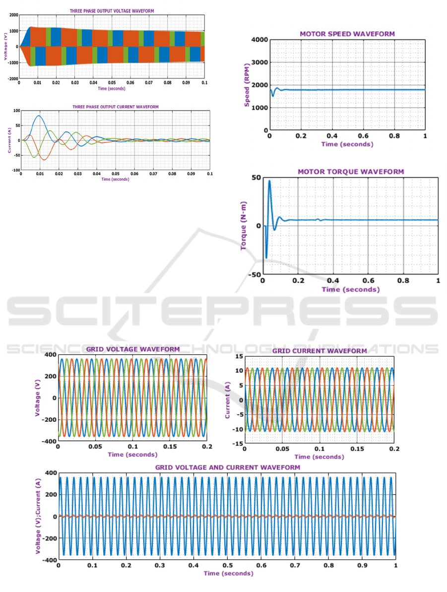
(a)
(b)
Figure 18: Three phase output waveform (a) Voltage, (b)
Current
The three phase voltage waveform depicted in
Figure 18(a) initially rises at a level of 1100V then
falls down and in Figure 18 (b) represents the initial
current value of 80A and then reduces gradually.
The Figure 19 (a) displays two waveforms of a
BLDC motor. The graph shows the motor speed,
initially rising rapidly to around 1800 RPM before
stabilizing. The Figure 19 (b) illustrates the torque,
which exhibits a sharp drop followed by a steady low
value.
(a)
(b)
Figure 19: Waveform of BLDC (a) Speed, (b) Torque
Figure 20: Grid Waveform (a) Voltage, (b) Current and (c) voltage and current
Artificial Neural Network-Based MPPT Controller for PV System Integrated with Grid and Induction Motor
729
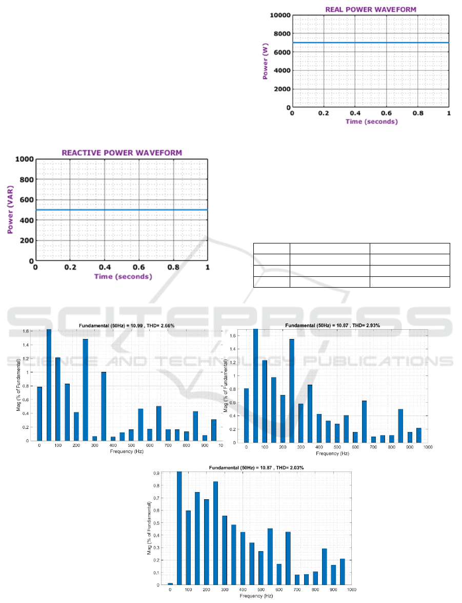
Figure 20 demonstrates grid voltage and current
waveforms, highlighting effective grid voltage
synchronization provided by the PI controller. Both
waveforms are perfectly sinusoidal, in phase, with
DFIG voltage at 370V and current at 12A. Figure
20(c) shows the pitch angle waveform of the DFIG.
Figure 21 illustrates the waveforms of real and
reactive power. The reactive power gradually
increases before stabilizing at a constant level (Fig.
21a), while the real power remains steady after a
certain point (Fig. 21b).
Figure 21: (a) Real power, (b) Reactive power waveform
Figure 22: illustrates Total Harmonic Distortion
(THD) under three-phase grid conditions. As shown
in 22(a), 22(b), and 22 (c), the harmonic distortion
levels are 2.66%, 2.93%, and 2.03% for the R, Y, and
B phases, respectively.
Table 2 Comparison of THD
Sl. No References THD
1 [16] 13%
2 [17] 6.1%
3Pro
p
ose
d
2.03%
Figure 22: Total Harmonic Distortion (THD)
INCOFT 2025 - International Conference on Futuristic Technology
730
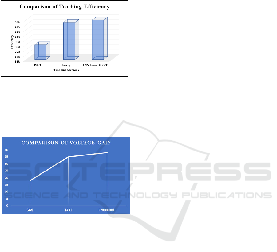
Table 2 presents a comparison of THD values,
showing that the MPPT approach results in a
minimized THD of 2.03%.
Figure 23: Comparison of Tracking Efficiency
The MPPT Tracking Efficiency Comparison of
the values is shown in Figure 23, with the intended
values for Perturbation & Observation (P&O) (Ali,
Mousa, et al. 2023), Fuzzy (Kumar and Channi, 2022)
and proposed ANN based MPPT being 88%, 93%
and 93.5%, respectively.
Figure 24: Comparison of Voltage Gain
Figure 24 illustrates the voltage gain of boost
converters, with recorded values of 18, 35 and 38. In
the proposed work, the converter achieves a voltage
gain of 38.
5 CONCLUSION
In this paper, integration of a PV system with an
induction motor and grid provides a promising
solution for sustainable energy generation and
efficient utilization in industrial and commercial
applications. By constantly adapting to
environmental changes like temperature and solar
irradiation, an ANN based MPPT controller greatly
increases efficiency of power extraction from the PV
system. With better tracking precision and quicker
convergence to the MPP, this unique MPPT method
performs better than conventional algorithms. The
efficient operation of the induction motor, driven by
solar energy, minimizes energy losses, while the grid
connection ensures stable power delivery and system
balance. MATLAB simulation results show that
proposed approach is effective, with a tracking
efficiency of 93.5% and a THD value of 2.03%.
Overall, this system represents a significant step
forward in optimizing renewable energy utilization
for sustainable power generation and efficient motor
operation. Future advancements may focus on real-
time implementation, Improved ANN technique, and
improved grid integration to achieve greater
efficiency, scalability, and reliability.
REFERENCES
Nahin, N. I., Biswas, S. P., Mondal, S., Islam, M. R., &
Muyeen, S. M. (2023) A modified PWM strategy with
an improved ANN based MPPT algorithm for solar PV
fed NPC inverter driven induction motor drives. IEEE
Access.
Villegas-Mier, C. G., Rodriguez-Resendiz, J., Álvarez-
Alvarado, J. M., Rodriguez-Resendiz, H., Herrera-
Navarro, A. M., & Rodríguez-Abreo, O. (2021)
Artificial neural networks in MPPT algorithms for
optimization of photovoltaic power systems: A
review. Micromachines, 12(10): 1260.
Idrissi, Y. E. A., Assalaou, K., Elmahni, L., & Aitiaz, E.
(2022) New improved MPPT based on artificial neural
network and PI controller for photovoltaic
applications. International Journal of Power Electronics
and Drive Systems, 13(3): 1791-1801.
Harndi, H., Regaya, C. B., & Zaafouri, A. (2020) A sliding-
neural network control of induction-motor-pump
supplied by photovoltaic generator. protection and
control of modern power systems, 5(1): 1-17.
Wongsathan, R. (2024) Integrated neural network-based
MPPT and ant colony optimization-tuned PI
bidirectional charger-controller for PV-powered motor-
pump system. Engineering and Applied Science
Research, 51(5): 605-617.
Yap, K. Y., Sarimuthu, C. R., & Lim, J. M. Y. (2020)
Artificial intelligence based MPPT techniques for solar
power system. Journal of Modern Power Systems and
Clean Energy, 8(6): 1043-1059.
Chojaa, H., Derouich, A., Chehaidia, S. E., Zamzoum, O.,
Taoussi, M., & Elouatouat, H. (2021) Integral sliding
mode control for DFIG based WECS with MPPT based
on artificial neural network under a real wind
profile. Energy Reports, 7: 4809-4824.
Elnozahy, A., Yousef, A.M., Abo-Elyousr, F.K.,
Mohamed, M. & Abdelwahab, S.A.M. (2021)
Performance improvement of hybrid renewable energy
sources connected to the grid using artificial neural
network and sliding mode control. Journal of Power
Electronics, 21: 1166-1179.
Artificial Neural Network-Based MPPT Controller for PV System Integrated with Grid and Induction Motor
731

Bana, P. R., D’Arco, S., & Amin, M. (2024) ANN-based
Robust Current Controller for Single-stage Grid-
Connected PV with Embedded Improved MPPT
Scheme. IEEE Access.
Vani, E., Balakrishnan, P., Singaram, G., & Senthil Kumar,
S. (2024) PV Wind Battery Based Dc Microgrid with
Neural Network MPPT. Journal of Electrical
Systems, 20(5s): 430-437.
Al-Jaboury, O. N. R., Hamodat, Z., & Daoud, R. W. (2024)
Design of Power Control Circuit for Grid-Connected
PV System-Based Neural Network. Journal of Robotics
and Control (JRC), 5(3): 821-828.
Mol, E. J., & Linda, M. M. (2023) Integration of wind and
PV systems using genetic-assisted artificial neural
network. Intelligent Automation and Soft
Computing, 35(2): 1471-1489.
Gowid, S., & Massoud, A. (2020) A robust experimental-
based artificial neural network approach for
photovoltaic maximum power point identification
considering electrical, thermal and meteorological
impact. Alexandria Engineering Journal, 59(5): 3699-
3707.
Kiran, S. R., Basha, C. H., Singh, V. P., Dhanamjayulu, C.,
Prusty, B. R., & Khan, B. (2022) Reduced simulative
performance analysis of variable step size ANN based
MPPT techniques for partially shaded solar PV
systems. IEEE access, 10: 48875-48889.
Mohammad, K. A. (2024) Optimization Of Solar Energy
Efficiency Using Neural Network Controllers With
Direct Current Converters.
Kumar, P. S., Sridhar, S., & Kumar, T. R. (2014) Design &
simulation of boost converter for power factor
correction and THD reduction. Int. Jr. of
ScientificEngg. & Tech. Res. IJSETR, 3(42): 8462-
8466.
Nazarkar, S., & Shelar, S. (2016) Design & Simulation Of
Active Power Factor Controller Using Boost
Converter. International Journal of Innovations in
Engineering Research and Technology, 3(3): 1-8.
Ali, A. I. M., Mousa, H. H., Mohamed, H. R. A., Kamel, S.,
Hassan, A. S., Alaas, Z. M., ... & Abdallah, A. R. Y.
(2023) An Enhanced P&O Mppt Algorithm With
Concise Search Area For Grid-Tied Pv Systems. IEEE
Access, 11: 79408-79421.
Kumar, R., & Channi, H. K. (2022) A PV-Biomass off-grid
hybrid renewable energy system (HRES) for rural
electrification: Design, optimization and techno-
economic-environmental analysis. Journal of Cleaner
Production, 349: 131347.
Pirpoor, S., Rahimpour, S., Andi, M., Kanagaraj, N.,
Pirouzi, S., & Mohammed, A. H. (2022) A novel and
high-gain switched-capacitor and switched-inductor-
based DC/DC boost converter with low input current
ripple and mitigated voltage stresses. IEEE Access, 10:
32782-32802.
Ahmad, J., Zaid, M., Sarwar, A., Lin, C. H., Asim, M.,
Yadav, R. K., ... & Alamri, B. (2021) A new high-gain
dc-dc converter with continuous input current for dc
microgrid applications. Energies, 14(9): 2629.
INCOFT 2025 - International Conference on Futuristic Technology
732
