
Impact of Sine PWM on Voltage THD in 5-Level Vs 7-Level
Inverters: A Comparative Analysis
Susheela Nunsavath
a
, Veena Chevula
b
, Shireesha Bollam
c
and Venkateswarlu Tadikamalla
d
Department of Electrical Engineering, Osmania University, Hyderabad, Telangana, India
Keywords: Multilevel Inverter, Total Harmonic Distortion, Modulation Technique.
Abstract: This study focuses on THD and various modulation strategies while analyzing 5-level and 7-level multilevel
inverters for grid systems. As they enable effective DC-to-AC conversion with advantages like lower
switching losses, improved output quality, and compact design, multilevel inverters are essential in renewable
energy applications. These inverters, which are widely used in industrial motor drives, PV systems, and
electric vehicle charging, promote sustainable energy solutions. According to simulation data, the 7-level
inverter provides the best performance with the lowest THD and outperforms the 5-level in terms of THD.
POD is the most successful SPWM approach for reducing THD, according to a comparison analysis. These
results highlight how advanced SPWM techniques and creative inverter designs can enhance grid integration
and power quality.
1 INTRODUCTION
An inverter is a device that converts direct current
(DC) electricity into alternating current (AC)
electricity, enabling the use of DC power sources, like
batteries or solar panels, to power AC appliances. .
This process involves converting a steady DC input
into a switching AC waveform, smoothing it into a
usable sine wave, and adjusting the output voltage as
needed. Inverters are widely used in solar systems,
UPS, electric vehicles, and industrial applications to
provide reliable AC power.
Multilevel Inverters (MLIs) are advanced
inverters designed for high-power and high-voltage
applications (Munawar, Iqbal, et al. , 2024). Unlike
conventional inverters that generate simple two-level
waveforms, MLIs produce a stepped AC output
resembling a sinusoidal waveform. This reduces
harmonic distortion, improves power quality, and
enhances efficiency.
Types of Multilevel Inverters (Singh and
Mohaney, 2024):
a
https://orcid.org/0000-0002-0142-0870
b
https://orcid.org/0009-0005-3058-8129
c
https://orcid.org/0009-0001-4566-7656
d
https://orcid.org/0009-0002-0364-3733
Diode-Clamped MLI: Uses diodes for voltage
balancing. Ideal for medium-voltage applications but
complex for high levels.
Flying Capacitor MLI: Balances voltage using
capacitors, offering redundancy and flexibility but
requiring complex balancing circuits.
Cascaded H-Bridge MLI: Uses multiple H-bridge
units powered by independent DC sources. It is
modular but needs isolated power sources.
Advantages of MLIs:
Power Quality: Reduced Total Harmonic
Distortion (THD) minimizes external filter
requirements.
Efficiency: Lower switching losses improve
energy efficiency.
Scalability: Easily adaptable to medium and
high-power applications.
Reduced Stress: Lower voltage stress enhances
component reliability.
Applications include renewable energy systems,
industrial drives, electric vehicles, and HVDC
transmission (José, Sheng, et al. , 2002). Despite their
complexity, MLIs offer unmatched efficiency,
550
Nunsavath, S., Chevula, V., Bollam, S. and Tadikamalla, V.
Impact of Sine PWM on Voltage THD in 5 - Level Vs 7 - Level Inverters: A Comparative Analysis.
DOI: 10.5220/0013625000004664
Paper published under CC license (CC BY-NC-ND 4.0)
In Proceedings of the 3rd International Conference on Futuristic Technology (INCOFT 2025) - Volume 3, pages 550-556
ISBN: 978-989-758-763-4
Proceedings Copyright © 2025 by SCITEPRESS – Science and Technology Publications, Lda.
making them essential for modern high-power
systems.
Challenges include higher costs, control
complexity, and space requirements, but these are
outweighed by their performance benefits (Susheela,
Chandra, et al. , 2024), (Leon, Vazquez, et al. , 2017).
2 MODULATION TECHNIQUE
SPWM is a modulation technique used to control the
output voltage and frequency of inverters (Akshay,
Rakshith, et al. , 2024), (Susheela and Kumar, 2017).
It generates switching signals by comparing a
sinusoidal reference waveform (desired output) with
a high-frequency triangular carrier waveform.
Sinusoidal Pulse Width Modulation (SPWM) is a
widely used technique for generating AC waveforms,
particularly in inverters and motor drive systems. It
modulates the width of pulses based on a sinusoidal
reference waveform to approximate a sinusoidal
output voltage.
There are many advantages of SPWM like
Improved Efficiency, Lower switching losses
compared to other modulation methods, Better
Harmonic Profile (By increasing the carrier
frequency, higher-order harmonics are shifted away
from the fundamental frequency, making filtering
easier) and Scalability (Output voltage and frequency
can be easily controlled by adjusting the reference
waveform).
In pulse-width modulation (PWM) techniques,
different switching methods are used to control the
inverter’s output waveform. PD (Phase Disposition),
POD (Phase Opposition Disposition), and APOD
(Alternate Phase Opposition Disposition) are multi-
carrier PWM techniques, primarily used in multilevel
inverters to manage how the carrier signals are
arranged. In multilevel inverters, several carriers are
needed because multiple levels of voltage are
generated. The arrangement of these carriers
determines the type of modulation technique (Abbas,
Majid, et al. , 2017), (Susheela and Kumar, 2017).
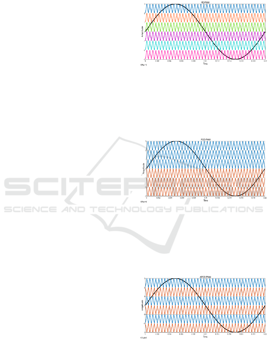
2.1 Phase Disposition
All carrier waves are in phase. Carriers are stacked
vertically as depicted in Figure 1, with each carrier
covering a specific range of the output voltage. The
reference sinusoidal waveform is compared against
all these carriers.
Figure 1: PD PWM Technique
2.2 Phase Opposition Disposition
Carriers are divided into two groups: The carriers
above the reference sinusoidal wave are in phas e
(Susheela and Kumar, 2020). The carriers below the
reference wave are 180° out of phase with those
above it as illustrated in Figure 2.
Figure 2: POD PWM Technique
2.3 Alternate Phase Opposition
Disposition
Each adjacent carrier is 180° out of phase with the
neighbouring carrier (Susheela and Kumar, 2019).
This alternating phase arrangement applies to all
carrier waves as indicated in Figure 3.
Figure 3: APOD PWM Technique
Impact of Sine PWM on Voltage THD in 5 - Level Vs 7 - Level Inverters: A Comparative Analysis
551
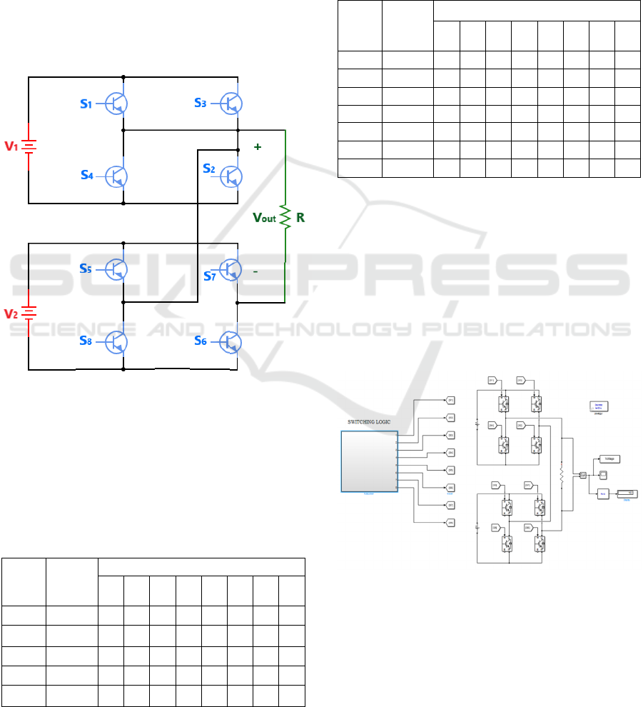
3 TOPOLOGY
The Cascaded H-Bridge (CHB) method is a widely
used topology in multilevel inverters due to its
modularity, scalability, and simplicity in
implementation (Ramaprabha, 2022), (Deshmukh,
Chaturvedi, et al. , 2022). It consists of multiple H-
bridge inverter units connected in series, each
producing a separate voltage level. By combining
these voltage levels, a stepped waveform
approximating a sinusoidal output can be generated,
which reduces total harmonic distortion (THD)
without requiring bulky filters (Babaei, 2008).
Figure 4: Inverter Topology
The topology shown in Fig. 4 is same for 5-Level and
7-Level Inverter. For a 5-Level Inverter voltages are
symmetrical such that V1 = 10 V and V2 = 10 V
whose switching table is provided in Table 1. H-
Bridges produce five levels in the output: +20 V, +10
V, 0, -10 V and -20 V.
Table 1: Switching table for 5 – Level Operation.
Mod
e
Outpu
t
Switching State
S
1
S
2
S
3
S
4
S
5
S
6
S
7
S
8
1 +20 V 1 1 0 0 1 1 0 0
2 +10 V 1 1 0 0 1 0 1 0
3 0 V 1 0 1 0 1 0 1 0
4 -10 V 0 0 1 1 1 0 1 0
5 -20 V 0 0 1 1 0 0 1 1
Similarly, for 7-Level Inverter operation mentioned
in Table 2, H-Bridges produce 7 levels: +30 V, +20
V, 10 V, 0, -10 V, -20 V, -30 V for asymmetric
voltages : V1 = 10 V and V2 = 20 V. Symmetrical
setups offer simpler design and control, while
asymmetrical configurations provide more levels
with fewer components, improving harmonic
performance.
Table 2: Switching table for 7 – Level Operation.
Mod
e
Outpu
t
Switching State
S
1
S
2
S
3
S
4
S
5
S
6
S
7
S
8
1 +30 V 1 1 0 0 1 1 0 0
2 +20 V 1 0 1 0 1 1 0 0
3 +10 V 1 1 0 0 1 1 0 0
4 0 V 1 0 1 0 1 0 1 0
5 -10 V 0 0 1 1 0 0 1 1
6 -20 V 1 0 1 0 0 0 1 1
7 -30 V 0 0 1 1 0 0 1 1
4 SIMULATION RESULTS
4.1 5 – Level Inverter
The Inverter is implemented in Matlab Simulink as
illustrated in Figure 5. V1 and V2 are chosen as 10 V.
The output has 5 levels ranging from +20 V to -20 V,
with an RMS value of voltage being 15.2 V.
Figure 5: Simulink Model of 5 – Level Operation
4.1.1 PD PWM
The output shown in Figure 6 is obtained for the 5-
level operation using PD PWM technique with its
respective THD in Figure 7.
INCOFT 2025 - International Conference on Futuristic Technology
552
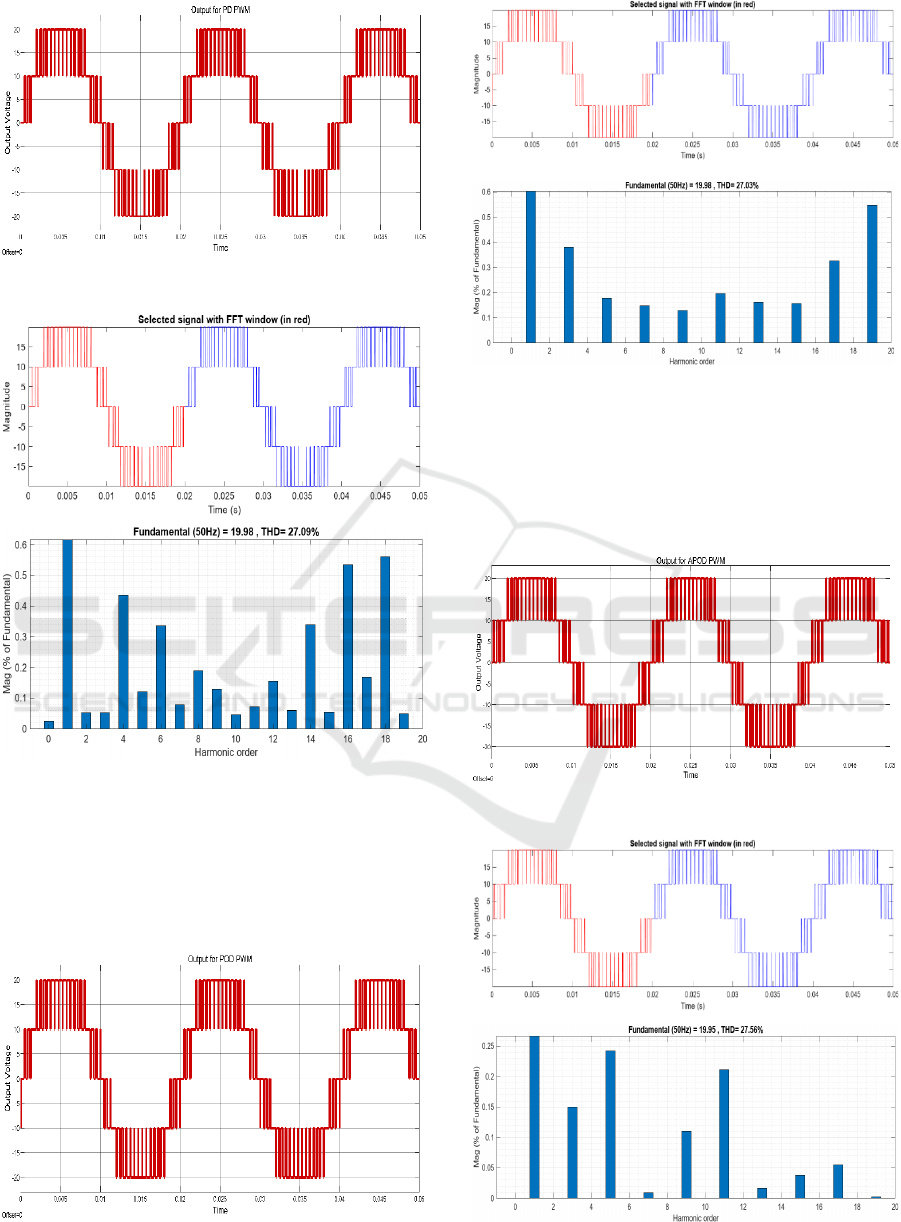
Figure 6: Output using PD PWM
Figure 7: Voltage THD using PD PWM
4.1.2 POD PWM
Using the POD PWM approach, the result seen in
Figure 8 is produced for the 5-level operation, with
the corresponding THD displayed in Figure 9.
Figure 8: Output using POD PWM.
Figure 9: Voltage THD using POD PWM.
4.1.3 APOD PWM
With the application of APOD PWM, the voltage
waveform obtained is in Figure 10 with its THD in
Figure 11.
Figure 10: Output using APOD PWM.
Figure 11: Voltage THD using APOD PWM.
Impact of Sine PWM on Voltage THD in 5 - Level Vs 7 - Level Inverters: A Comparative Analysis
553
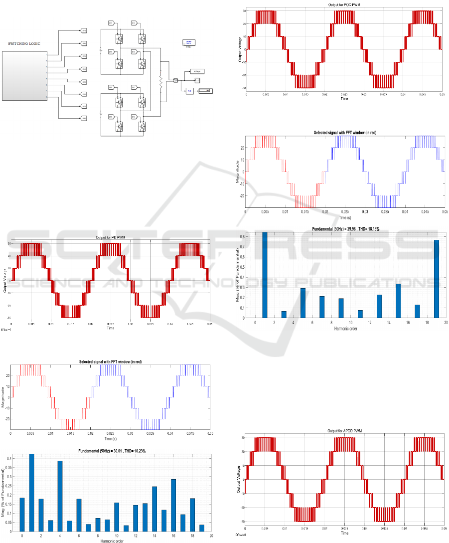
4.2 7 – Level Inverter
Figure 12 shows how the inverter is configured in
Matlab Simulink. V1 and V2 have been set to 10 V
and 20 V respectively. The output contains seven
voltage levels, from +30 V to -30 V, and its RMS
value is 22.4 V.
Figure 12: Simulink model of 7 - Level Operation.
4.2.1 PD PWM
By using the PD PWM technique, the output obtained
is depicted in Figure 13 with the voltage THD in
Figure 14.
Figure 13: Output using PD PWM
Figure 14: Voltage THD using PD PWM.
4.2.2 POD PWM
Using the POD PWM, the result seen in Figure 15 is
produced for the 7-level operation, with the
corresponding voltage THD displayed in Figure 16.
Figure 15: Output using POD PWM.
Figure 16: Voltage THD using POD PWM
4.2.3 APOD PWM
The output shown in Figure 17 is obtained for the 7-
level operation using APOD PWM technique with its
respective voltage THD in Figure 18.
Figure 17: Output using APOD PWM.
INCOFT 2025 - International Conference on Futuristic Technology
554
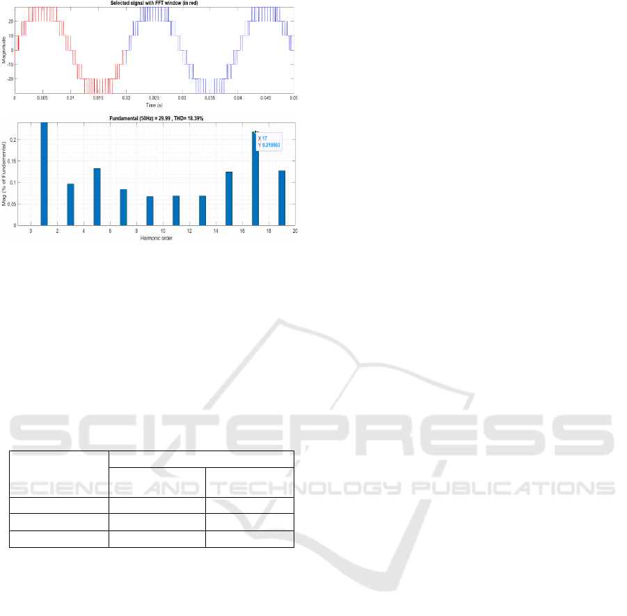
Figure 18: Voltage THD using APOD PWM.
Table 3 shows the comparison of voltage THD
among the PD, POD and APOD modulation
techniques for 5-level and 7-level operation of the
inverter. It is evident from the table that the POD
modulation technique is optimal to use, since it is able
to produce less THD in comparison to other
techniques. It can be observed that increment in the
number of levels is causing the lower value of THD.
Table 3: Comparision of Voltage THD.
Modulation
Technique
Voltage THD (%)
5-level
operation
7-level
operation
PD 27.09 18.23
POD 27.03 18.18
APOD 27.56 18.39
5 CONCLUSION
This study highlights the significance of multilevel
inverters, particularly 5-level and 7-level
configurations, in improving grid integration and
power quality for renewable energy applications by
focusing on Total Harmonic Distortion and various
modulation strategies. The comparative analysis
reveals that the 7-level inverter demonstrates superior
performance with the lowest THD, making it a more
efficient choice over the 5-level counterpart for
achieving optimal power quality. Furthermore, the
investigation of SPWM strategies identifies POD as
the most effective approach for minimizing THD.
These findings emphasize the potential of advanced
SPWM techniques to further enhance the
performance of multilevel inverters in grid systems.
These characteristics make them indispensable in
applications such as industrial motor drives,
photovoltaic systems, and electric vehicle charging
stations. Overall, the study underscores the critical
role of innovative inverter designs and sophisticated
modulation strategies in advancing sustainable
energy solutions. The results provide a strong
foundation for future research aimed at optimizing
multilevel inverters to meet the evolving demands of
modern power systems.
REFERENCES
PECon 2012 : 2012 IEEE International Conference on
Power and Energy : the Magellan Sutera Resort, Kota
Kinabalu, Malaysia : 2 to 5 December 2012. IEEE,
2012.
2013 IEEE Power & Energy Society General Meeting.
IEEE, 2013.
S. Munawar, M. S. Iqbal, M. Adnan, M. A. Akbar, and A.
Bermak, “Multilevel Inverters Design, Topologies, and
Applications: Research Issues, Current, and Future
Directions,” IEEE Access, 2024, doi:
10.1109/ACCESS.2024.3472752.
S. Singh and S. Mohaney, “Improving THD% using
Multilevel Inverter and Comparing Different Types of
Multilevel Inverter,” in 2024 5th International
Conference for Emerging Technology, INCET 2024,
Institute of Electrical and Electronics Engineers Inc.,
2024. doi: 10.1109/INCET61516.2024.10593239.
R. José, L. Jih-Sheng, and P. Fangzheng, “Multilevel
inverters: A survey of topologies, controls, and
applications,” IEEE Transactions on Industrial
Electronics, vol. 49, no. 2, pp. 724–738, 2002.
N. Susheela and V. Revanth Chandra, “THD analysis of 15-
level multilevel inverter using lesser number of
switches with nearest level control technique,”
International Journal of Power Electronics and Drive
Systems (IJPEDS), vol. 15, no. 3, pp. 1609–1616, Sep.
2024, doi: 10.11591/ijpeds.v15.i3.pp1609-1616.
J. I. Leon, S. Vazquez, and L. G. Franquelo, “Multilevel
Converters: Control and Modulation Techniques for
Their Operation and Industrial Applications,”
Proceedings of the IEEE, vol. 105, no. 11, pp. 2066–
2081, Nov. 2017, doi: 10.1109/JPROC.2017.2726583.
S. Akshay, P. Rakshith, Malegowda, N. Chandana, and K.
B. Darshan Gowda, “A Comparative Study of PD, POD
and APOD PWM Techniques with Sinusoidal PWM
Reference Signal on 5 Level Cascaded H Bridge
Inverter,” in 2024 Asia Pacific Conference on
Innovation in Technology, APCIT 2024, Institute of
Electrical and Electronics Engineers Inc., 2024. doi:
10.1109/APCIT62007.2024.10673670.
N. Susheela and P. S. Kumar, “Performance Evaluation of
Carrier Based PWM Techniques for Hybrid Multilevel
Inverters with Reduced Number of Components,”
Energy Procedia, vol. 117, pp. 635–642, Jun. 2017, doi:
10.1016/j.egypro.2017.05.164.
Impact of Sine PWM on Voltage THD in 5 - Level Vs 7 - Level Inverters: A Comparative Analysis
555

M. Q. Abbas, A. Majid, J. Saleem, and M. Arif, “Design
and Analysis of 15-level Asymmetric Multilevel
Inverter with Reduced Switch Count using Different
PWM Techniques,” in Proceedings - 2017 International
Conference on Frontiers of Information Technology,
FIT 2017, Institute of Electrical and Electronics
Engineers Inc., Jul. 2017, pp. 333–338. doi:
10.1109/FIT.2017.00066.
N. Susheela and P. Satish Kumar, “Performance evaluation
of multicarrier based techniques for single phase hybrid
multilevel inverter using reduced switches,” Indonesian
Journal of Electrical Engineering and Computer
Science, vol. 7, no. 3, pp. 676–686, Sep. 2017, doi:
10.11591/ijeecs.v7.i3.pp676-686.
N. Susheela and P. S. Kumar, “Evaluation of POD and
APOD multicarrier SPWM techniques for three-phase
seven-level diode clamped multilevel inverter fed
induction motor drive using FPGA,” International
Journal of Power Electronics, vol. 12, no. 3, p. 282,
2020, doi: 10.1504/IJPELEC.2020.110063.
N. Susheela and P. S. Kumar, “Performance evaluation and
comparison of diode clamped multilevel inverter and
hybrid inverter based on PD and APOD modulation
techniques,” International Journal of Advances in
Applied Sciences, vol. 8, no. 2, p. 143, Jun. 2019, doi:
10.11591/ijaas.v8.i2.pp143-153.
R. Ramaprabha, “A Single Phase Multilevel Inverter with
Cascaded Basic Units,” in 2022 IEEE 3rd Global
Conference for Advancement in Technology, GCAT
2022, Institute of Electrical and Electronics Engineers
Inc., 2022. doi: 10.1109/GCAT55367.2022.9972151.
G. Deshmukh, P. Chaturvedi, and V. Rajderkar, “Single
phase Cascaded H-Bridge Multilevel Inverter
Topology,” in 2022 International Conference on
Futuristic Technologies (INCOFT), IEEE, Nov. 2022,
pp. 1–6. doi: 10.1109/INCOFT55651.2022.10094514.
E. Babaei, “A Cascade Multilevel Converter Topology
With Reduced Number of Switches,” IEEE Trans
Power Electron, vol. 23, no. 6, pp. 2657–2664, Nov.
2008, doi: 10.1109/TPEL.2008.2005192.
INCOFT 2025 - International Conference on Futuristic Technology
556
