
Battery Management System in Autonomous Drones
Mahip Nagori and Deepa Nath
Department of Electrical and Electronics Engineering,
Dr. Vishwanath Karad University MIT World Peace University, Kothrud, Pune, India
Keywords: Battery Management System, Autonomous Drone, Power Management, Safety Protocols, Voltage
Step-Down, Real-Time Monitoring, Mission-Critical.
Abstract: Autonomous drones are extremely adaptable flying devices that are being used more and more in mission-
critical sectors where reliability, safety, and operational efficiency are improved by reducing human
involvement. Applications including package delivery, obstacle avoidance, aerial surveys, environmental
monitoring, and disaster response that need extreme precision and quick decision-making depend heavily on
these drones. The Battery Management System (BMS), An essential circuit that ensures secure yet efficient
power usage while reducing battery-related dangers, is essential to their dependable operation. With
sophisticated multi-level protection circuits (over-current, overcharge/discharge, and thermal) and accurate
voltage and current sensing via a small, noise-resistant PCB layout, this study offers a revolutionary BMS
design specifically suited for autonomous drones. In contrast to traditional designs, the suggested BMS
seamlessly interacts with flight control systems by combining real-time monitoring with improved
communication capabilities via CAN protocol. This design greatly increases drone operational lifespan and
ensures mission success under difficult conditions by enhancing power management precision and system
robustness.
1 INTRODUCTION
Unmanned aerial vehicle (UAV) technology has
advanced quickly, which has accelerated its
incorporation into a variety of applications, such as
package delivery, disaster relief, agricultural
monitoring, and aerial surveillance (Bláha, Severa,
et al. , 2023), (Telli, et al. , 2023) Drones are still
primarily constrained by their reliance on lithium-
based batteries, which have a low energy density.
This makes it difficult to conduct continuous
autonomous operations because it limits flying times
to tens of minutes. Despite the potential benefits
offered by developing battery technologies,
technical and monetary obstacles continue to prevent
their broad implementation (Jiao, Zhang, et al. ,
2023), (Sarsembayev, Yazdi, et al. , 2022). Effective
Battery Management Systems (BMS) are necessary
to get around these restrictions. In addition to
monitoring cell voltage and temperature and
preventing battery-related risks including
overcharging, over-discharging, and overheating, a
BMS guarantees safe operation (Bláha, Severa, et al.
, 2023) (Sarsembayev, Yazdi, et al. , 2022)..
Additionally, sophisticated BMS designs include
functions like real-time communication with drone
control systems and cell balancing, which are
essential for prolonging battery life and guaranteeing
safe navigation during missions (Jiao, Zhang, et al. ,
2023), (Liu, Liu, et al. , 2018) .
Additionally, current
trends highlight effective, lightweight BMS systems
that are customized for the limitations of UAVsClick
or tap here to enter text..
Innovative methods to improve battery
management are highlighted in the literature now in
publication. To reduce downtime during recharge
cycles, for example, automatic battery swapping
systems and external charging stations have been
proposed (Sarsembayev, Yazdi, et al. , 2022)
Onboard BMS upgrades are a more practical way to
achieve higher flight efficiency and safety, but, as
these technologies increase operational complexity
and call for more infrastructure (Jiao, Zhang, et al. ,
2023), (Liu, Liu, et al. , 2018).
The design and deployment of a complete low-
voltage BMS specifically suited for autonomous
drones is presented in this study. Along with
sophisticated monitoring features, (Huang,
Simandjuntak, et al. , 2018) the system has
protection methods like heat, short-circuit, and
Nagori, M. and Nath, D.
Battery Management System in Autonomous Drones.
DOI: 10.5220/0013618000004664
Paper published under CC license (CC BY-NC-ND 4.0)
In Proceedings of the 3rd International Conference on Futuristic Technology (INCOFT 2025) - Volume 3, pages 393-399
ISBN: 978-989-758-763-4
Proceedings Copyright © 2025 by SCITEPRESS – Science and Technology Publications, Lda.
393

overcurrent safeguards. This BMS, which bridges
the gap between traditional designs and the changing
requirements of UAV technology, was created with
STM32 microcontrollers and optimized with
inexpensive components to assure safe, dependable
operations across a variety of applications.
2 LITERATURE REVIEW
This BMS's concepts of effective power use and real-
time monitoring are informed by the Droneport idea,
which was proposed by Bláha et al. (Bláha, Severa,
et al. , 2023) and focused on automated battery
management systems for UAVs. In their study of
UAV applications, Telli et al. (Telli, et al. ,
2023)emphasized the value of sophisticated BMS in
mission-critical situations when safety and
dependability are crucial.
The focus on integrating overcurrent, overcharge,
and heat protection in this design is consistent with
Jiao et al.'s(Jiao, Zhang, et al. , 2023) identification
of BMS research hotspots, including cell balance and
multi-level safety. The need of precise current
sensing and real-time data processing to maintain
battery health during operations was highlighted by
Sarsembayev et al. (Sarsembayev, Yazdi, et al. ,
2022) in their research on dynamic wireless power
transmission using LiPo battery modelling.
Liu et al. created an automated docking and
battery-swapping system for UAVs (Liu, Liu, et al. ,
2018)], emphasizing the significance of smooth
communication protocols like the CAN protocol used
in this BMS and automation in power management.
For drone-based inspections, Huang et al. (Huang,
Simandjuntak, et al. , 2018) developed intelligent
BMS designs, highlighting the need for adaptable
protection techniques in a range of environmental
circumstances.
In their discussion of drone BMS design
problems, Jadhav and Bhosale placed a strong
emphasis on reliable communication systems and
small PCB layouts. This is consistent with the multi-
layer PCB layout of the suggested design, which
improves electromagnetic compatibility and reduces
noise. The exact sensing circuits used in this research
were informed by Lakkireddy and Mathe's
(Lakkireddy and Mathe, 2022) suggested techniques
for precise voltage, current, and temperature
measurements utilizing linear optocouplers.
The incorporation of protective measures was led
by the industry standards for BMS examined by
Gabbar et al. (Gabbar, Othman, et al. , 2022), which
placed a strong emphasis on fault-tolerant designs
and adherence to safety procedures. Prognostics and
system health management strategies were
emphasized by Guo et al. (Guo, Li, et al. , 2021),
who also emphasized the importance of real-time
problem detection and reporting for this BMS's
communication capabilities.
The sophisticated balancing techniques employed
in this design to increase battery life were influenced
by the evaluation of battery balancing techniques
conducted by Scholarworks and Bartek (Bartek, , et
al. , 2019). Degradation prognostics for lithium-ion
battery packs were studied by Che et al. (Che, Deng,
et al. , 2020), which emphasized the project's
emphasis on predictive maintenance and
dependability.
The Zener diode-based design used in this BMS
was informed by Khan's (Khan, , et al. , 2022)
thorough analysis of overcharge prevention circuits.
The microcontroller-driven method for data
collection and real-time analysis was influenced by
Eskandari et al.'s(Eskandari, Venugopal, et al. , 2022)
discussion of enhanced battery electronics
integration. The effective and space-efficient layouts
of this project were guided by Bergström's emphasis
on compact PCB redesign methodologies.
To solve electromagnetic compatibility concerns
that are essential to dependable data transfer, Wey et
al. (Wey, Hsu, et al. , 2013) investigated EMI
avoidance in CAN-based cmomunication for BMS.
To provide insights into layout optimization for
reliable performance, Lee et al. (Lee, Yao, et al. ,
2017) investigated PCB ground regions and their
function in EMI suppression.
The goals of this BMS are in line with those of
Nizam et al.'s assessment of BMS design
considerations for lithium-ion batteries(Nizam,
Maghfiroh, et al. , 2020), which placed a strong
emphasis on efficiency and safety. To provide the
real-time monitoring and processing capabilities that
are essential to this architecture, Rabbani (Rabbani, ,
et al. , 2014) emphasized microcontroller-based data
gathering devices. A very dependable overcurrent
protection circuit was presented by Ding and Feng
(Ding, and, Feng, 2013), strengthening the hardware-
based security measures included in this BMS.
3 DESIGN ARCHITECTURE AND
FUNCTIONALITY OF THE BMS
By keeping an eye on vital battery factors like
voltage, current, and temperature, the BMS
guarantees peak performance, dependability, and
INCOFT 2025 - International Conference on Futuristic Technology
394
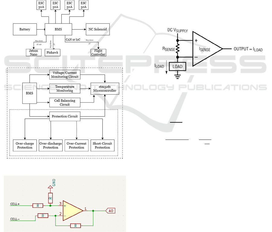
safety. The battery is protected under a variety of
operating scenarios by its sophisticated protective
mechanisms as shown in figure 1, which guard
against overcharge, over discharge, overcurrent, and
thermal runawayClick or tap here to enter text..
Adaptive controls and emergency safety procedures
are made possible by its real-time communication
with the flight controller.
An op-amp-based subtractor circuit is used to
measure the voltage across each battery pack cell.
Compared to a basic voltage divider, this method
reduces mistakes and allows for exact differential
measurement by taking into consideration the
common ground shared by cells. Figure 2 gives a
rundown of the circuit used. To avoid overcharge
and over discharge situations, the voltage data is sent
in real time (Lakkireddy and Mathe, 2022), (Gabbar,
Othman, et al. , 2022).
Figure 1: BMS Block Diagram
Figure 2: Overview of single voltage cell (subtractor
circuit)
A shunt resistor connected to a current detecting
amplifier is used to measure current. This is very
similar to the voltage sensing circuit as the voltage
drop is very minimal across the shunt and that
voltage across the shunt is calculated using a
subtractor circuit, as depicted in figure 3, that value
is sent to the microcontroller and further the current
is calculated using ohms law. High-precision
amplifiers minimize power dissipation across the
resistor while enabling precise overcurrent condition
detection. The flight controller receives the real-time
current values (Guo, Li, et al. , 2021), (Bartek, , et
al. , 2019).
To identify temperature irregularities, NTC
thermistors are positioned thoughtfully across the
cells. When safe operating thresholds are surpassed,
protection mechanisms are activated through the
control systems by the temperature data that is fed
into the microcontroller's ADC for thermal
management and is sent to the flight controller
(Lakkireddy and Mathe, 2022), .
Figure 3: Overview of Shunt Placement (without
protection)
Calculation of temperature using a 12-bit ADC:
Vout =
… (1)
T = [(
) * (
)] - 273.15 (2)
T = Temperature in Kelvin
Vref = Reference voltage supplied to the
thermistor circuit
Vout = Measured voltage from the thermistor
𝛽 = Beta coefficient (a constant specific to the
thermistor type)
R0 = Nominal resistance of the thermistor at a
given temperature
R = Thermistor resistance at the recorded
temperature (calculated from Vout and circuit
resistance)
For the overcharge circuit each cell is connected
to a transistor-zener based circuit, which disconnects
charging path when specified voltage limits are
Battery Management System in Autonomous Drones
395
surpassed. The whole circuit is tuned for maximum
cell voltage charging limit, using zener diode, which
is connected to base of the transistor, when the diode
is activated (i.e., cell is fully charged) the transistor
redirects the charging current to a dummy load,
described in figure 4 below. This stops the cells
from overcharging and elongating the battery life .
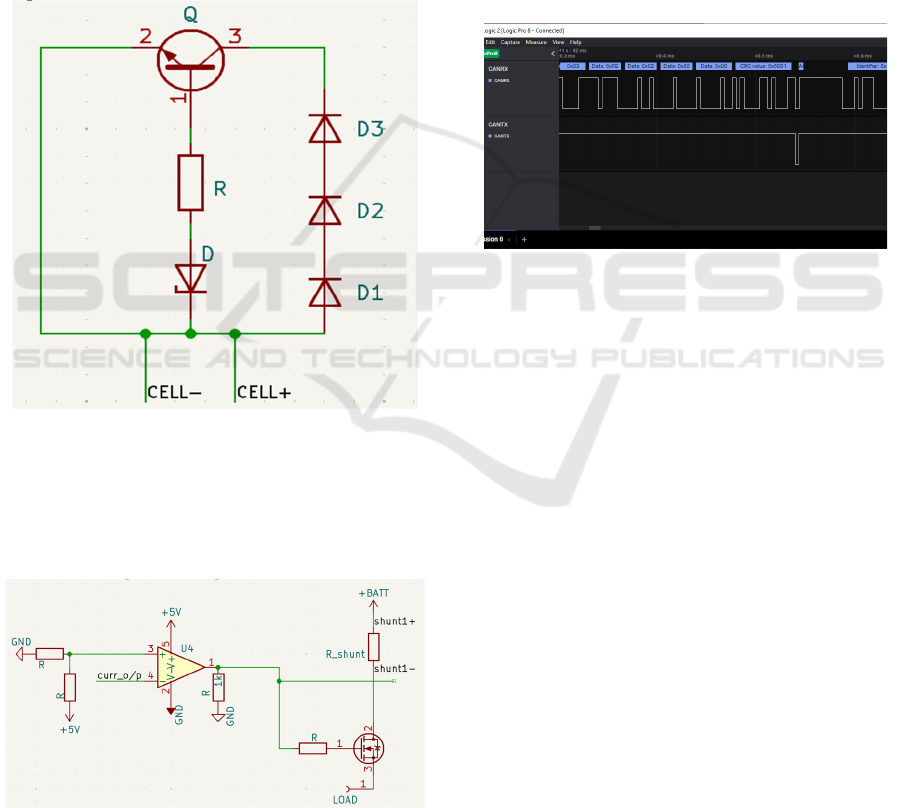
In order to protect against overcurrent through a
comparator, which is also an opamp-based circuit,
the current sensing circuit compares the output
voltage, or the voltage relative to the current value
that the load is consuming, with a reference value, or
the voltage at the highest current value . When the
drain connects to the load, the comparator circuit's
output drives a MOSFET that is connected
Figure 4: Overview of overcharge circuit
to the shunt and determines whether current will
flow. The whole circuit is explained in figure 5.
When there is an overcurrent, the comparator output
drops, disconnecting the load by shutting off the
MOSFET (Ding, and, Feng, 2013).
Figure 5: Overview of Over-Current Circuit
To guarantee precise battery parameter
monitoring, the BMS's firmware controls data
collection, processing, and communication. ADC
peripherals transform analog inputs into calibrated
digital values by sampling signals (Rabbani, , et al. ,
2014) from temperature, voltage, and current
sensors. Error codes are produced for dangerous
situations once these variables are continuously
evaluated to identify threshold violations (Rabbani, ,
et al. , 2014) . Reactive measures like load reduction
and emergency landing are made possible via the
CAN system, which enables reliable, fast
communication of real-time data and fault codes to
the flight controller(Wey, Hsu, et al. , 2013). During
autonomous drone missions, this integration
guarantees effective operation, improves safety, and
preserves system reliability. A CAN data signal is
given below in figure 6.
Figure 6: CAN Reception Signal on Logic Analyzer
A PCB built for stability, compactness, and
electromagnetic compatibility houses the BMS.
High-current components are segregated to lessen
interference, and differential couples diminish noise
in sensor connections. Heat is dissipated during
high-current operations by thermal vias and heat
sinks. By offering low-impedance channels, ground
planes stabilize power during current fluctuations
and lessen noise in delicate circuits Click or tap here
to enter text.. Transient voltage spikes are filtered by
decoupling capacitors, and the microcontroller is
protected by reverse polarity diodes and connections
such as JST-XH, XT60, and Phoenix. The
autonomous drone's BMS is guaranteed to operate
dependably and safely owing to this architecture.
INCOFT 2025 - International Conference on Futuristic Technology
396

4 TESTING RESULTS AND
ANALYSIS
Figure 7: Load Current v/s Current Sense o/p Voltage
Figure 8: Load Current v/s OCP o/p
Figure 9: Load Current v/s Load Voltage
The Current Sensing and Overcurrent Protection
(OCP) circuit is demonstrated in the LTSpice
simulation. In order to identify overcurrent
situations, a subtractor circuit amplifies the voltage
across a shunt resistor network by ten and then
passes it via a comparator. The output plot in figure
7 displays the load voltage response, the amplified
sensing voltage, and the comparator's change from
high to low in figure 8 when the current above 30A.
Plot in figure 9 indicates that the NMOSFET shuts
off during overcurrent situations.
A subtractor topology is used in the Voltage
Sensing Circuit simulation for a 3S battery
arrangement to assess the voltages of individual cells
while taking the accumulated voltages of previous
cells into consideration. The circuit's precision in
detecting and adjusting cell voltages for ADC
interface with the microcontroller is validated by the
output plot in figure 10.
Battery Management System in Autonomous Drones
397

Figure 10: Cell Voltage v/s o/p of the Voltage Sense
Circuit
The overcharge protection circuit for a single cell
in a 3S battery system is shown in the LTSpice
diagram. It makes use of a transistor for switching, a
Zener diode for monitoring cell voltage, and a
dummy load to release extra power in the event of
overcharging.
As the Zener diode conducts at 4.2V, activating
the transistor, figure 11 displays an increase in the
base current of the transistor. Concurrently increase
in the current in the dummy load in figure 12
indicates that protection is engaged and the battery
cell is completely charged. The circuit's activation at
the designated threshold is confirmed by the cell
voltage plot.
Figure 11: Cell Voltage v/s Base Current
Figure 12: Cell Voltage v/s Dummy Load current
5 CONCLUSIONS
A key component of dependability, effectiveness,
and safety, the Battery Management System (BMS)
designed for autonomous drones guarantees
consistent performance in mission-critical
applications. The BMS offers real-time defect
detection and proactive reaction to critical
circumstances by combining accurate current and
voltage monitoring, thermal management, and
reliable communication via the CAN protocol. By
avoiding component damage and reducing hazards
like thermal runaway, advanced safety features, such
as overcurrent and overcharge protections, guarantee
safe operationClick or tap here to enter text..
Effective power distribution maximizes energy use
and prolongs battery life when paired with clear
visual indicators and fault reporting. Autonomous
drones can now do longer and more taxing jobs like
package delivery, environmental monitoring, and
disaster response thanks to this thorough and
creative design, which also increases their
operational reliability. By striking a balance between
technological advancement and real-world
implementation, the BMS raises the bar for
autonomous systems' efficiency and safety
REFERENCES
L. Bláha, O. Severa, M. Goubej, T. Myslivec, and J.
Reitinger, ‘Automated Drone Battery Management
System—Droneport: Technical Overview’, Drones,
vol. 7, no. 4, Apr. 2023, doi: 10.3390/drones7040234.
K. Telli et al., ‘A Comprehensive Review of Recent
Research Trends on Unmanned Aerial Vehicles
(UAVs)’, Aug. 01, 2023, Multidisciplinary Digital
Publishing Institute (MDPI). doi:
10.3390/systems11080400.
S. Jiao, G. Zhang, M. Zhou, and G. Li, ‘A Comprehensive
Review of Research Hotspots on Battery Management
Systems for UAVs’, 2023, Institute of Electrical and
Electronics Engineers Inc. doi:
10.1109/ACCESS.2023.3301989.
INCOFT 2025 - International Conference on Futuristic Technology
398

B. Sarsembayev, S. S. Heidari Yazdi, A. Kapanov, and M.
Bagheri, ‘LiPo Battery Modeling for Dynamic
Wireless Power Transfer in UAV Application’, in
2022 11th International Conference on Renewable
Energy Research and Application (ICRERA), 2022,
pp. 346–351. doi:
10.1109/ICRERA55966.2022.9922909.
Z.-N. Liu, X.-Q. Liu, L.-J. Yang, D. Leo, and H.-W. Zhao,
‘an Autonomous Dock and Battery Swapping System
for Multirotor UAV’, 2018, doi:
10.13140/RG.2.2.19437.90085.
D. Huang, S. Simandjuntak, V. Becerra, A. Fraess-
Ehrfeld, and H. Ma, ‘An Intelligent BMS for Drone-
Based Inspection of Offshore Wind Turbines’.
Jadhav, Vinay & Bhosale, Surendra. (2022). Battery
Management System for Drones.
G. R. Lakkireddy and S. E. Mathe, ‘A Strategy for
Measuring Voltage, Current and Temperature of a
Battery Using Linear Optocouplers’, World Electric
Vehicle Journal, vol. 13, no. 12, Dec. 2022, doi:
10.3390/wevj13120225.
H. A. Gabbar, A. M. Othman, and M. R. Abdussami,
‘Review of Battery Management Systems (BMS)
Development and Industrial Standards’, Jun. 01, 2021,
MDPI. doi: 10.3390/technologies9020028.
Wei. Guo, Steven. Li, and Qiang. Miao, 2019 Prognostics
and System Health Management Conference : PHM-
Qingdao : October 25-27, 2019, Qingdao, China.
IEEE, 2019.
S. Scholarworks@gvsu and W. Bartek, ‘Passive and
Active Battery Balancing Methods Implemented on
Second Use Lithium-ion Batteries’, 2020. [Online].
Available: https://scholarworks.gvsu.edu/theses/975
Y. Che, Z. Deng, X. Tang, X. Lin, X. Nie, and X. Hu,
‘Lifetime and Aging Degradation Prognostics for
Lithium-ion Battery Packs Based on a Cell to Pack
Method’, Chinese Journal of Mechanical Engineering
(English Edition), vol. 35, no. 1, Dec. 2022, doi:
10.1186/s10033-021-00668-y.
K. Khan, ‘Design and Implementation of a Battery
Overcharge protection Circuit’, 2024, doi:
10.13140/RG.2.2.23262.82245.
[ICNERE : the 4th International Conference on Nano
Electronics Research and Education : toward advanced
imaging science creation : 27-29 November 2018, S-
Port, Hamamatsu Campus, Shizuoka University,
Hamamatzu, Japan. Institute of Electrical and
Electronics Engineers, 2018.
ECTI-CON 2013 : 2013 10th International Conference on
Electrical Engineering/Electronics, Computer,
Telecommunications and Information Technology :
Krabi, Thailand : May 15-17, 2013. IEEE, 2013.
L. Ding and Q. Feng, ‘A high reliable over-current
protection circuit with low power consumption’, in
Proceedings - 2013 5th International Conference on
Intelligent Human-Machine Systems and Cybernetics,
IHMSC 2013, 2013, pp. 462–465. doi:
10.1109/IHMSC.2013.116.
G. Rabbani, ‘Microcontroller Based Data Acquisition
System’, 2014. [Online]. Available:
https://www.researchgate.net/publication/281443326
C.-L. Wey, C.-H. Hsu, K.-C. Chang, P.-C. Jui, and M.-T.
Shiue, ‘EMI Prevention of CAN-Bus-Based
Communication in Battery Management Systems’,
2013.
C.-H. Lee, C.-Y. Yao, H.-C. Li, D.-B. Lin, and H.-P. Lin,
‘The Study of PCB Ground Area and Location on EMI
Reduction Effectiveness’, 2017.
E. Bergström, ‘Redesign of a Printed Circuit Board for a
Battery Management System A Master Thesis within
Production Management’.
M. Nizam, H. Maghfiroh, R. A. Rosadi, and K. D. U.
Kusumaputri, ‘Battery management system design
(BMS) for lithium ion batteries’, in AIP Conference
Proceedings, American Institute of Physics Inc., Apr.
2020. doi: 10.1063/5.0000649.
R. Eskandari, P. Venugopal, and G. Rietveld, ‘Advanced
Battery Management Systems with Integrated Battery
Electronics’, in 2022 IEEE 20th International Power
Electronics and Motion Control Conference, PEMC
2022, Institute of Electrical and Electronics Engineers
Inc., 2022, pp. 55–61. doi:
10.1109/PEMC51159.2022.9962868.
Battery Management System in Autonomous Drones
399
