
PV/ Wind/ Battery/ Grid Integrated Hybrid Energy System for EV
Charging Station
Meghana Sonar, Sanjana Aralikatti
Mruthyunjaya Belavatagi and Siddarameshwar H N
Dept of Electrical and Electronics, KLE Technological University, Vidyanagar, Hubballi, India
Keywords: RES, HES, Wind System, PV System, Fuzzy MPPT, EV Charging
Abstract: As fossil fuel supplies run out, renewable energy sources, or RESs, are becoming increasingly important. Due
to their accessibility and user-friendliness, solar and wind energy systems are the most popular RESs. In order
to improve energy efficiency and dependability, this work combines solar (PV) panels, wind energy systems,
and electric vehicle (EV) charging stations into a hybrid energy system (HES). A Maximum Power Point
Tracking (MPPT) system based on fuzzy logic is used to maximize energy conversion in wind and
photovoltaic systems. A fuzzy MPPT controller is used by the wind subsystem to maximize turbine output
under variable wind conditions, while the PV system adapts to changing irradiance, temperature, and
nonlinear circumstances for optimal solar energy harvesting. A charge controller regulates battery energy,
ensuring efficient charging and state of charge (SOC) monitoring. A grid-connected inverter transforms DC
to AC for grid interfacing and a boost converter controls DC voltage for DC loads. Buck-boost converters
control voltage and provide real-time SOC, current, and voltage monitoring for EV batteries. When paired
with pulse width modulation (PWM), the fuzzy MPPT algorithm ensures efficient power flow throughout the
system. Key performance variables, including battery state of charge, load voltage, and current, are
continuously monitored. This hybrid system aims to enhance sustainability and energy efficiency for EV
charging applications in MATLAB/Simulink.
1 INTRODUCTION
The growing need for efficient and sustainable energy
solutions emphasizes how important renewable
energy sources are to solving the world's energy
problems. In particular, solar and wind energy
provide clean, plentiful, and environmentally friendly
substitutes for traditional fossil fuels, which makes
them crucial for cutting greenhouse gas emissions and
halting climate change. In hybrid energy systems,
combining photovoltaic (PV) and wind energy units
takes advantage of their complementary qualities,
where wind may make up for decreased solar output
in
low light levels, guaranteeing a more steady and
dependable energy supply. Furthermore, by
optimizing energy extraction under various
environmental conditions, Maximum Power Point
Tracking (MPPT) algorithms increase the efficiency
of these systems, maximizing performance and
lowering operating costs.
Hybrid energy systems not only improve energy
reliability, but they also help to maintain grid stability
by eliminating variations in power generation and
demand. By incorporating energy storage
technologies such as modern battery systems, these
setups may store extra energy created during peak
production periods and release it during high-demand
periods, assuring continuous energy availability.
Furthermore, the hybrid approach reduces the chance
of power interruptions, especially in rural or off-grid
areas, making it an excellent choice for increasing
energy access in underserved areas.
Grid connectivity strengthens these systems by
allowing for bi-directional energy flow, where
surplus energy may be supplied back into the grid,
generating additional revenue streams and
encouraging a circular energy economy. This also
enables flawless synchronization with the main grid
during periods of high demand, improving system
adaptability and scalability for future energy
requirements.
This work aims to create an integrated energy
system that maximizes the possibilities of renewable
energy and innovative storage technologies. It
220
Sonar, M., Aralikatti, S., Belavatagi, M. and H N, S.
PV/ Wind/ Battery/ Grid Integrated Hybrid Energy System for EV Charging Station.
DOI: 10.5220/0013612500004664
Paper published under CC license (CC BY-NC-ND 4.0)
In Proceedings of the 3rd International Conference on Futuristic Technology (INCOFT 2025) - Volume 3, pages 220-228
ISBN: 978-989-758-763-4
Proceedings Copyright © 2025 by SCITEPRESS – Science and Technology Publications, Lda.

includes sophisticated control systems to ensure
energy efficiency and system stability. The
technology seeks to serve essential applications like
EV charging infrastructure by offering a sustainable
and efficient energy solution. This approach not only
promotes the adoption of electric vehicles by
addressing their charging needs, but it also helps to
achieve the larger aims of lowering greenhouse gas
emissions, improving energy security, and fostering
energy independence. Furthermore, the hybrid
system's adaptability allows for scaling, making it
suitable for a variety of geographical regions and
energy demands. This ensures its relevance in both
urban and remote places, encouraging widespread
adoption of sustainable energy technologies.
1.1 MPPT METHODS
MPPT (Maximum Power Point Tracking) is an
algorithm in charge controllers that maximizes the
output power of PV modules by changing the
operating point to the maximum power point. This
maximizes the energy yield from sunlight, increasing
the efficiency of solar power systems.
The efficiency of The HES (Hybrid Energy
System) based EV Charging Station can be enhanced
by applying following MPPT algorithms:
1.1.1 Perturb and Observe Technique
(P&O)
The Perturb and Observe (P&O) technique tracks the
maximum power point (MPP) by gradually adjusting
PV voltage. While oscillations can happen near the
maximum power point (MPP) in steady-state settings,
it tends to shift toward the MPP as power increases.
It is extensively used because of its versatility and
simplicity, and improvements increase its efficiency.
1.1.2 Incremental Conductance (INC)
The Incremental Conductance method calculates
the maximum power point (MPP) by comparing
incremental conductance to array conductance. It
carefully adjusts voltage to maintain MPP under
changing situations. In comparison to P&O, this
approach is speedier and less likely to cause
oscillations.
1.1.3 Modified Perturb and Observe (P&O)
The modified P&O MPPT algorithm improves on
classic P&O by decreasing oscillations around the
MPP and increasing tracking speed. It handles quick
variations in irradiance or temperature by using
adaptive step sizes or anticipatory adjustments. This
improves both efficiency and stability in power
extraction.
1.1.4 Fuzzy MPPT
The fuzzy MPPT algorithm uses fuzzy logic to
determine the maximum power point (MPP) by
modifying step size in response to irradiance and
temperature. It provides rapid, steady, and adaptive
tracking with minimal oscillations, making it perfect
for dynamic environments.
Among the MPPT algorithms stated above, the
fuzzy MPPT method was chosen for the hybrid
energy EV charging station because it is fast,
adaptive, resistant to nonlinearity, and successfully
manages hybrid system integration.
Because of its versatility, accuracy, and dynamic
reaction, the fuzzy MPPT algorithm is favoured for
managing abrupt changes in temperature and
irradiance. It employs fuzzy logic to deliver faster,
more reliable tracking of the maximum power point
(MPP) with fewer oscillations than traditional
techniques like P&O and INC. It effectively harvests
maximum power under a variety of scenarios by
dynamically altering step sizes, guaranteeing the
smooth integration of grid, PV, wind, and battery
systems. This outperforms conventional MPPT
algorithms in terms of energy yield, stability, and
overall hybrid energy system performance for EV
charging.
2 LITERATURE SURVEY
The proposed work(Muthammal, 2018) focuses
on a hybrid solar and wind energy system for EV
recharging to meet long-distance travel needs. A
MATLAB-Simulink model demonstrates significant
power generation under various scenarios. Battery
swapping reduces charging time, increasing EV
adoption and lowering emissions.
In this work titled (Jatoth, 2024)
MATLAB/Simulink is used to demonstrate a multi-
input transformer-coupled active bridge converter
with PV, wind, and battery storage. The stand-alone
system maintains steady DC and AC voltages and
utilizes P&O MPPT to maximize power extraction. It
PV/ Wind/ Battery/ Grid Integrated Hybrid Energy System for EV Charging Station
221
ensures consistent power delivery under fluctuating
load and environmental circumstances.
In the study (Savio, Juliet, et al. , 2019), the author
proposed an on-grid solar and wind hybrid system for
EV charging that provides dependable power while
decreasing grid dependency. It reduces renewable
intermittency, lowers carbon emissions, and provides
long-term savings. The system promotes green
transportation and encourages the use of hybrid
renewable energy systems.
In this work (Katageri, Nisahathfareen, et al. ,
2021) the researcher, In order to reduce pollution and
grid reliance, the author developed a hybrid fast-
charging system that uses local renewable energy. For
EV charging, a MATLAB-Simulink model illustrates
how solar and wind energy operate under various
circumstances. By cutting down on charging time,
battery switching encourages EV adoption and
contributes to a cleaner environment.
In the proposed work (Reddy and Birudala, 2024),
the researcher developed an off-grid PV-based EV
charging station that uses energy storage systems
(ESS) rather than grid electricity. The system
produces enough energy based on irradiance and
temperature, with ESS providing backup when solar
power is insufficient. The model is both cost-effective
and sustainable. It demonstrates the potential for
future EV charging applications.
In this work (Kumar and Rajan, et al. , 2023), the
author in order to efficiently satisfy load demands,
MATLAB/Simulink was used to simulate a hybrid
energy system (HES) that included PV, WECS, a
diesel generator, and battery storage. MPPT
algorithms and converters ensure voltage
management and consistent performance. The
method is ideal for both remote communication and
precise watering. During periods of low demand,
surplus power can be fed back into the system.
3 METHODOLOGY
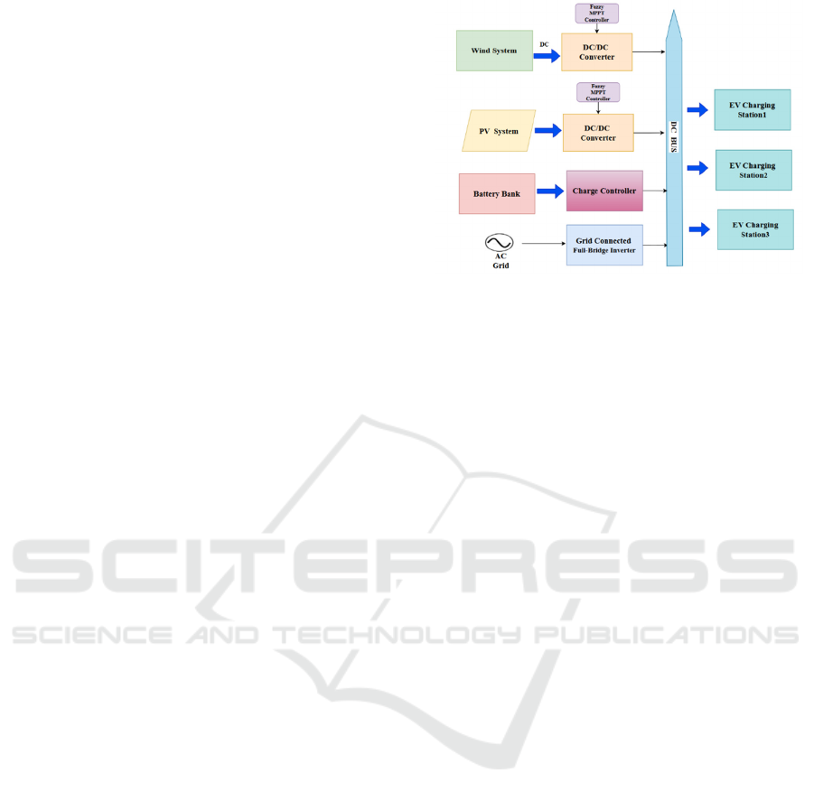
Fig.1 shows the block diagram of the proposed
method and the motivation behind developing the
HES based EV Charging station is to promote a
cleaner and eco-friendly transportation instead of
depending on fossil fuels.
Figure 1: Block Diagram of HES based EV Charging
Station
This block diagram illustrates a hybrid energy
system that combines wind, solar (PV), battery
storage, and the AC grid to power EV charging
stations.
The wind and PV systems create DC power,
which is optimized with fuzzy MPPT controllers and
DC/DC converters. Excess energy is stored in the
battery bank and regulated by a charge controller.
When renewable sources are insufficient, the AC grid
provides electricity, which is converted to DC using
a full-bridge inverter. The DC bus takes electricity
from multiple sources and transfers it to three EV
charging stations, ensuring efficient and long-lasting
power delivery.
The proposed system Illustrates the
MATLAB/Simulink model of HES based EV
Charging Station.
In order to guarantee a dependable
power source for EV charging, the hybrid energy
system integrates solar (PV) and wind energy with
battery storage, charge controllers, and grid
connectivity. Energy from renewable sources is
controlled and directed by charge controllers to either
the DC bus for instant consumption or the battery for
storage. While buck-boost regulators effectively
charge EV batteries, the grid-connected inverter
synchronizes with the grid for energy consumption or
output.
Hence let’s understand the working of whole
model in a Detailed manner :
INCOFT 2025 - International Conference on Futuristic Technology
222
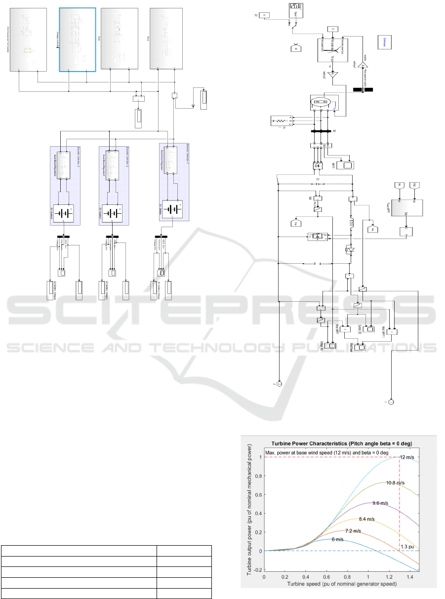
Figure 2: Shows the Simulation of the proposed system
3.1 Wind System
The figure depicts the wind system which has a
variable input source. In a In a hybrid energy system,
wind energy is converted into electrical power using
a turbine, generator, rectifier, and boost converter
with MPPT management. The generated electricity is
fed into a DC bus, which charges batteries, powers
the grid, and provides renewable energy for EV
charging. It ensures effective energy use and
complements solar PV. Therefore, the specifications
of Wind System are illustrated in the given below
Table 1
Table 1: Specifications of Wind System
Nominal mechanical out
p
ut
p
owe
r
2.5kW
Base power of the electrical generato
r
2777.8VA
Base wind spee
d
12m/s
Maximum power at base wind spee
d
1pu
Base rotational s
p
ee
d
1.3m/s
Figure 3: Simulation of Wind System
Figure 4: Turbine Speed vs Turbine output power
characteristics of wind Turbine for 6 to 12m/s
PV/ Wind/ Battery/ Grid Integrated Hybrid Energy System for EV Charging Station
223
The above figure depicts the speed vs output
power characteristics of WECS or Wind system of
EV Charging station for 6 to 12m/s and a fixed pitch
angle (β=0 degrees). The turbine highlights the ideal
operating locations for the greatest efficiency at each
wind speed by achieving maximum power at a certain
turbine speed.
3.2 PV System
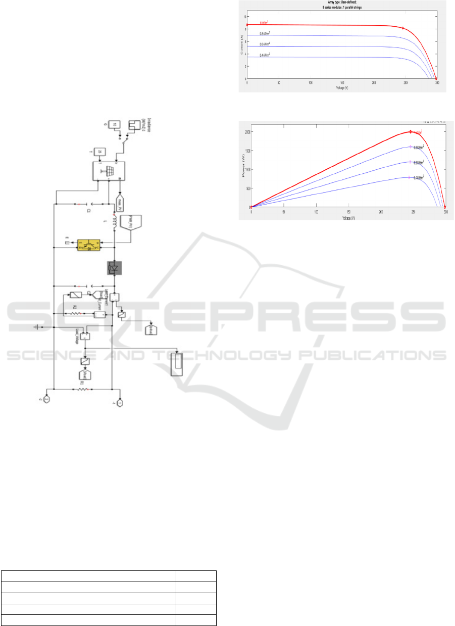
Figure 5: Simulation of PV system
The above figure illustrates the PV system in
which the hybrid energy arrangement that turns solar
irradiance into DC electricity via solar panels. A DC-
DC converter with MPPT optimizes power
production, and energy is stored in batteries or
delivered directly for EV charging. It integrates
smoothly with wind and grid inputs to ensure
consistent energy delivery.
Table 2: Specifications of PV System
Maximum Power
(
W
)
250.205
Open circuit voltage Voc (V) 37.3
Short circuit current Isc (A) 8.66
Voltage at maximum power point Vmp (V) 30.7
Current at maximum
p
ower
p
oint Im
p
(
A
)
8.15
Figure 6(a): V-I Characteristics of PV Panel
Figure 6 (b): P-V Characteristics of PV Panel
Figure 6(a) Illustrates the V-I Characteristics of
PV Panel Which is a plot of Current(A) vs Voltage
(V) of PV Panel where the results reveal that the
voltage and current oscillate steadily following
transients, and the power stabilizes at a constant
amount. This demonstrates that the recommended
control technique is successful.
Figure 6(b) Illustrate the P-V Characteristics of
PV Panel under varying irradiance levels, which is
plot of Power (W) vs Voltage (V) of PV Panel that
shows the system's versatility that indicate a change
in the maximum power point with increasing
irradiance. This demonstrates how adaptable it is to
changes in the environment.
The PV installation has to ensure that the panels
receive the most sunlight possible, and the charging
station's solar plant area (Area α Power output) is
minimal. Some may suggest using high-power
concentrators to boost power production; however,
doing so raises the cost.
The plant's cost and upkeep. Choosing hybrid
solutions like wind, biomass, or small hydro plants
is a better idea. For dry regions, a solar-wind hybrid
is the greatest choice when taking integration costs
and efficiency into account.
The PV installation has to ensure that the panels
receive the most sunlight possible, and the charging
station's solar plant area (Area α Power output) is
minimal. Some may suggest using high-power
concentrators to boost power production; however,
doing so raises the cost.
INCOFT 2025 - International Conference on Futuristic Technology
224
The plant's cost and upkeep. Choosing hybrid
solutions like wind, biomass, or small hydro plants
is a better idea. For dry regions, a solar-wind hybrid
is the greatest choice when taking integration costs
and efficiency into account.
3.2 Fuzzy MPPT controller for Wind
and PV System
Figure 7: Simulation of Fuzzy MPPT controller
The fuzzy MPPT controller uses fuzzy logic to
calculate the appropriate duty cycle for the DC-DC
converter. It uses inputs such as PV voltage and
current to track the maximum power point (MPP)
under changing irradiance and temperature
conditions, assuring maximum energy extraction
from the PV system.
3.3 Charge Controller
Figure 8: Simulation of Charge controller
The above figure illustrates the charge controller
controls the flow of power between the battery, EVs,
and PV/wind energy sources. It keeps the battery
from being overcharged or deeply discharged,
extending its lifespan. For optimum system efficiency
and smooth grid integration, it also controls energy
distribution. Let’s understand the working of charge
controller in depth
The producing plant uses MPPT control, and the
charging control is mostly reliant on the ESS's SOC
and power supply. The terms Power from Hybrid
Plant (Hp), Power Demand (Pd), and SOC of ESS
(Se) refer to its four operating modes.
Mode 1:
When PP > PD and SE is within maximum
and minimum limits, electricity is given to the EV and
surplus power is sent to ESS.
Mode 2: When PP>PD and SE is out of limits, the
surplus power will be given to grid or connected to
dummy loads for Power balance.
Mode 3:
When PP, PD, and SE are between
limitations, ESS supplies the demand from EV.
Mode 4: When Hp < Pd and Se < minimal value,
energy demand is taken from grid to DC bus. If our
charging station is in an off- grid area, we intend to
operate in the above 3 modes. Similar to a solar plant.
Figure 9: Battery Voltage vs Time, Battery Current vs
Time, SOC vs Time output
The above figure illustrates the output of battery
whose working is observed in Charge controller.
The
battery voltage stabilizes, the current varies while
charging, and the state of charge (SOC) increases
linearly with time, according to the data. This attests
to the battery charging system's efficient operation.
PV/ Wind/ Battery/ Grid Integrated Hybrid Energy System for EV Charging Station
225
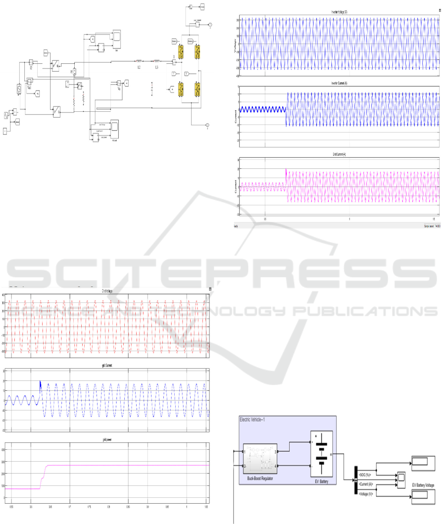
3.3 Grid connected Full bridge DC-AC
Converter
Figure 9: Simulation of Grid connected Full bridge DC-AC
Converter
The hybrid energy system's grid-connected full-
bridge DC-AC converter converts DC power from
renewable sources and batteries into AC power that is
synced with the voltage and frequency of the power
grid. It allows the system to either export surplus
energy to the grid or draw energy when demand
exceeds generation, guaranteeing a consistent power
supply for EV charging.
Figure 10: Grid Voltage vs Time, Grid Current vs Time,
Grid power vs Time outputs
Figure 10 illustrates the output Grid whose
working is observed in Grid connected Full bridge
DC-AC Converter. Here we can observe that battery
performs efficiently when the SOC rises gradually,
the voltage stays constant, and the current
dynamically fluctuates in response to changes in the
load.
Figure 11. Inverter Voltage vs Time, Inverter Current vs
Time, Grid Current vs Time output
Figure 11 illustrates the outputs of inverter whose
working is observed in Grid connected Full bridge
DC-AC Converter. The results indicate that after
initial transients, inverter voltage and current stabilize,
and grid current synchronizes. This attests to reliable
functioning and good grid integration.
3.4 EV Charging Station
Figure 12: Simulation of EV Charging Station
If the EV charging station above is not linked to
the hybrid energy system, it gets its electricity straight
from the grid. Power converters transform the AC
INCOFT 2025 - International Conference on Futuristic Technology
226
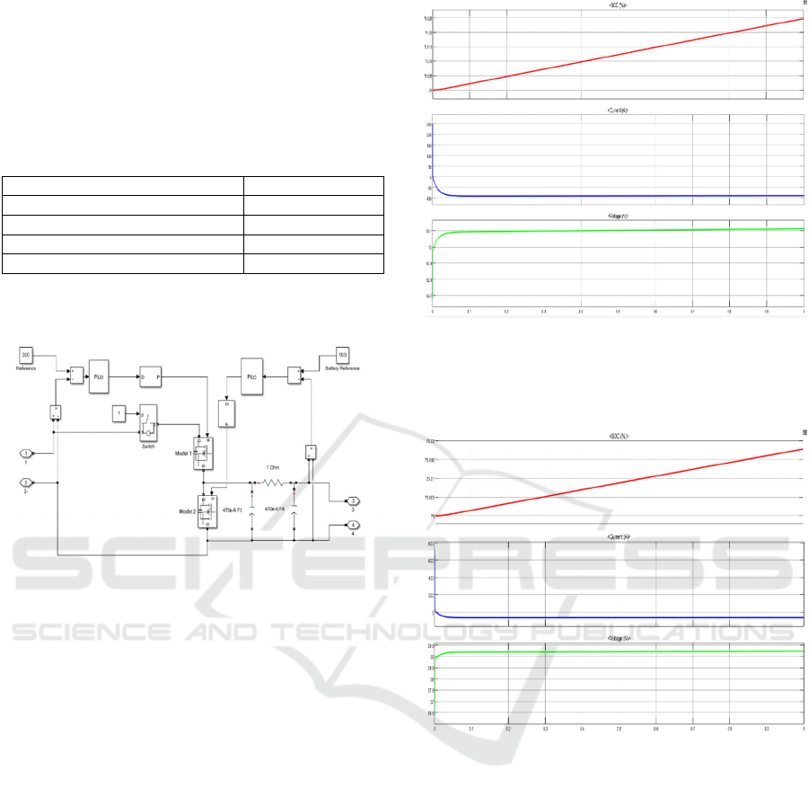
power from the grid into the proper DC voltage.
Buck-boost regulators guarantee that the voltage is
changed to satisfy the unique charging needs of the
EV battery, resulting in safe and effective charging.
The Specifications of EV battery are shown below.
Table 2. Specifications of EV Battery
T
yp
e Lithium-Ion
Nominal Volta
g
e
(
V
)
12
Rated Ca
p
acit
y
(
Ah
)
100
Initial State-of-Charge(%) 75
Battery response time (s) 30
Figure 13: Simulation of Buck-Boost Regulator of EV
Charging Station
An EV charging station's buck-boost regulator
modifies the hybrid energy system's voltage to meet
the needs of the EV battery. In order to ensure a
steady and effective charging process and safeguard
the battery from overvoltage or undervoltage
situations, it adjusts the input voltage as necessary.
In this way all the subsystems integrated with Hybrid
energy system collectively work together.
4 RESULTS
4.1 Results for EV Charging Station 1
The simulation results in Figure 14 indicate that
while charging, SOC increases linearly, current
decreases exponentially, and voltage stabilizes with
time. This attests to the system's effective and
regulated battery charging mechanism.
Figure 14: SOC, current and voltage vs time for EV
Charging Station 1
4.2 Results for EV Charging Station 2
Figure 15: SOC, current and voltage vs time for EV
Charging Station 2
The simulation results in Figure 15 demonstrate
the battery's performance under load, with SOC
dropping linearly, current stabilizing following an
initial transient, and voltage attaining steady state,
assuring a consistent energy supply.
4.3 Results for EV Charging Station 3
The simulation results demonstrate the battery's
behaviour under load, with SOC dropping linearly,
current stabilizing after an initial transient, and
voltage attaining steady state, resulting in constant
energy production.
PV/ Wind/ Battery/ Grid Integrated Hybrid Energy System for EV Charging Station
227
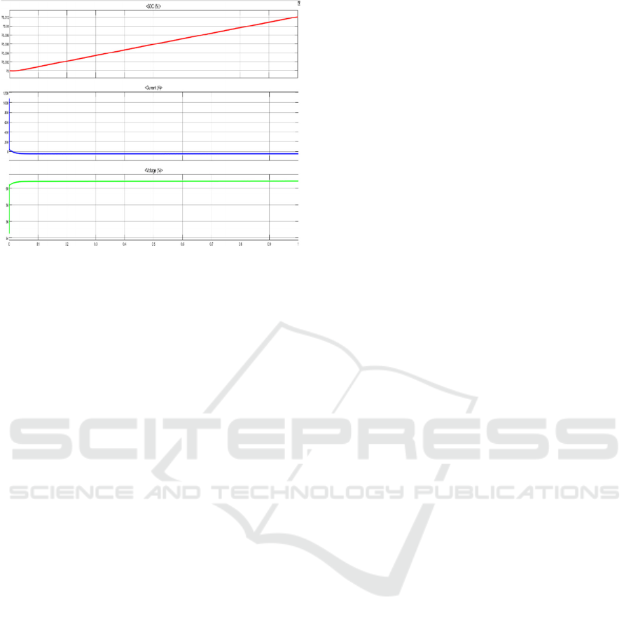
Figure 16: SOC, current and voltage vs time for EV
Charging Station 3
5 CONCLUSIONS
The PV/Wind/Battery/Grid Integrated Hybrid Energy
System for EV Charging Stations provides an
economical and environmentally friendly way to
satisfy the increasing energy needs of EVs. The
system guarantees a consistent and dependable power
supply by utilizing renewable energy sources such as
wind and solar power, in addition to battery storage
and grid connectivity.
It limits reliance on non-renewable energy
sources, maximizes energy use, and lowers carbon
emissions. Sophisticated power converters, charge
controllers, and energy management systems enhance
its overall efficiency and operating stability. In
addition to meeting EV charging requirements, this
hybrid strategy makes a substantial contribution to the
worldwide shift to cleaner and greener energy
systems.
6 FUTURE SCOPE
Future improvements include incorporating AI-
powered smart grids, blockchain for energy trading,
and vehicle-to-grid (V2G) technology to improve
energy management. Improvements in battery
technology, Calculation of both SOC and SOH. Ultra-
fast charging will boost system performance.
REFERENCES
R., Muthammal. (2018). Solar and Wind Energy based
charging station for Electric Vehicles. International
Journal of Advanced Research in Electrical Electronics
and Instrumentation Engineering. 7.
Ramesh Jatoth. (2024). PV Wind Based Stand-Alone Multi
Input Electric Vehicle Charging Stations. International
Journal of Intelligent Systems and Applications in
Engineering, 12(23s), 920–926. Retrieved from
https://ijisae.org/index.php/IJISAE/article/view/7063
https://jespublication.com/uploads/2024V15I70102.pd
f
Savio, D.A.; Juliet, V.A.; Chokkalingam, B.; Padmanaban,
S.; Holm-Nielsen, J.B.; Blaabjerg, F. Photovoltaic
Integrated Hybrid Microgrid Structured Electric
Vehicle Charging Station and Its Energy Management
Approach. Energies 2019, 12, 168.
https://doi.org/10.3390/en12010168
https://www.ijnrd.org/papers/IJNRD2312166.pdf
S. HN, P. M. Katageri, P. R, Nisahathfareen and A. P,
"Development of PV/Wind/Generator based Grid
Integrated Hybrid Energy System," 2021 IEEE Mysore
Sub Section International Conference (MysuruCon),
Hassan, India, 2021, pp.1-5, doi:
10.1109/MysuruCon52639.2021.9641665.
Reddy, Birudala & Chengaiah, Prof. (2024). A Solar-Wind
based EV Charging Station Model using MATLAB
Simulink. IOP Conference Series: Earth and
Environmental Science. 1382. 012003. 10.1088/1755-
1315/1382/1/012003.
R. Tharwin Kumar, C. Christober Asir Rajan, Integration of
hybrid PV-wind system for electric vehicle charging:
Towards a sustainable future, e-Prime - Advances in
Electrical Engineering, Electronics and Energy,
Volume 6,2023,100347, ISSN 2772-6711,
https://doi.org/10.1016/j.prime.2023.100347.
INCOFT 2025 - International Conference on Futuristic Technology
228
