
Optimization and Validation of Microstrip Patch Antenna for
Endoscopy Application
Juily Nachiket Tarade
1a
and Uday Pandit Khot
2
1
Electronics and Telecommunication Engineering Department, Ramrao Adik Institute of Technology, Nerul, Navi Mumbai,
Mumbai University, Maharashtra, India
2
Electronics and Telecommunication Engineering Department, St. Francis Institute of Technology, Borivali,
MumbaiUniversity, Maharashtra Maharashtra, India
Keywords: Microstrip Patch Antenna, Electromagnetic Bandgap, Non-Invasive, Specific Absorption Rate, Wireless
Capsule Endoscopy, Link Budget.
Abstract: Compared to standard endoscopy, wireless capsule endoscopy with non-invasive antennas has gained more
attention. Since the transmitting antenna of a wireless capsule endoscope (WCE) is located inside the body as
opposed to the receiving antenna, which is located outside of it, designing the transmitting antenna is a
difficult challenge. Simultaneously achieving high data rates, small size, omni-directionality, acceptable
specific absorption rate (SAR), and large bandwidth in telemetry systems are major hurdles faced by these
antennas. This is because many parts of the gastrointestinal tract have different dielectric constants and
thicknesses. To overcome these obstacles, antennas must be characterized for WCE. With a modified partial
ground plane, the suggested antenna is a small planar slotted microstrip patch antenna. It is a miniature
ingestion-capable Ultra-Wide Band (UWB) antenna. The substrate material for the antenna is Rogers TMM
13i. An environment that roughly represents the full human gastrointestinal (GI) tract, including surrounding
tissues is created using the High Frequency Structure Simulator (HFSS 13.0). The performance of the antenna
is evaluated by placing it in the middle of the various GI tracts. The suggested antenna's dimensions are 40
mm
3
(10 mm × 10 mm × 0.4 mm) and is a mere 1.26 percent of the capsule's volume. About 4.3 GHz and 6.7
GHz, with a -3 dB bandwidth of about 20.4 MHz and 950 MHz, respectively, are the resonant frequencies.
The advantage of having multiple resonant frequencies is that the proposed single antenna can be used for all
the GI tract although the dielectric constant varies over the entire GI tract. The existing literature needs
different antennas for different GI tracts. In the biological model, the radiation pattern is circularly polarized
and omnidirectional. The maximum radiation efficiency of 95.65% has been observed. For the purpose of
biocompatibility analysis, the SAR value in the GI tract is also calculated and is in well limit. Once patch is
designed for endoscopy application, it needs to be validated which can be done with the help of link budget
where A
P
> R
P.
To establish a stable communication link between the endoscopic antenna and external device,
the antenna power (A
p
) should be higher than the required power (R
p
).
1 INTRODUCTION
Today's cutting-edge wireless capsule endoscopy
technology replaces the conventional endoscopy
method, which uses a wired endoscope to diagnose
the digestive tract. Due to the fact that endoscopy can
only access the duodenum, which is the upper portion
of the small intestine, because of its horrible
consequences, particularly in younger aged
individuals and children (Mulugu and Saha , 2020).
a
https://orcid.org/0009-0008-2851-5707
A contemporary non-invasive method for diagnosing
life-threatening conditions including inflammatory
small intestinal diseases like Crohn's disease is called
wireless capsule endoscopy. Cancer, colon polyps,
tumours, and gastrointestinal bleeding in the
digestive tract that, if discovered at preliminary
phases (Mulugu and Saha , 2020). Therefore, this
diagnosing method which has gained attention
recently is of the utmost relevance. The antenna,
which transfers image data from the sophisticated
CMOS image sensor in the capsule to the on-body
Tarade, J. N. and Khot, U. P.
Optimization and Validation of Microstrip Patch Antenna for Endoscopy Application.
DOI: 10.5220/0013611900004664
Paper published under CC license (CC BY-NC-ND 4.0)
In Proceedings of the 3rd International Conference on Futuristic Technology (INCOFT 2025) - Volume 3, pages 197-205
ISBN: 978-989-758-763-4
Proceedings Copyright © 2025 by SCITEPRESS – Science and Technology Publications, Lda.
197

receiver antennas, is a crucial part of the wireless
capsule endoscopy system. The challenge of
designing a miniaturised antenna that can fit into a
capsule of this size and still leave room for other
essential components like LEDs, a CMOS imager, an
antenna, a battery, and other electronics arises from
the capsule's size restrictions due to the narrow
passageways of the digestive system (Mulugu and
Saha , 2020). An antenna with an omnidirectional
radiation pattern is necessary due to the capsule's
uncontrollably orientated orientation. Another design
problem to satisfy high data rate needs for
transmitting high-resolution images at fast frame
rates is wide bandwidth. Furthermore, the antenna's
broad bandwidth lessens the impact of significant
frequency fluctuations on its performance, allowing it
to endure the fluctuating conditions of the digestive
system (Sarestoniemi, et al. , 2020). Recent history
reports a great deal of research and advancement in
this field.
A compact planar slotted microstrip patch antenna
with a modified partial ground plane and resonance
frequencies of around 4.3 and 6.6 GHz is the
proposed antenna in this research. The design of this
structure at UWB frequency offers a significant deal
of opportunity for increasing bandwidth and utilizing
UWB technology's low power and high penetration
capabilities, among other benefits. The size of the
proposed antenna is 90 mm
3
(10 mm × 10 mm × 0.9
mm) which is only 1.26% of the capsule volume.
Normally the capsule is of (26x11 mm
2
). The
radiation pattern is omnidirectional with circular
polarization in the biological model. It is observed
that the maximum radiation efficiency is 95.65%. The
EBG structure is optimized using the Particle Swarm
Optimization (PSO) method in order to reduce SAR.
There is significant reduction in SAR values at every
stage of GI track. SAR values significantly decrease
over the whole GI track. The EBG structure causes a
little drop in gain (15.65% decrease in antenna gain
in the esophagus at 6.7 GHz as compared to the
absence of EBG), but this has no effect on the gearbox
because the radiated power (2.89 mW) and radiation
efficiency (typically ranges between 40% and 70%)
are within an acceptable range. The acceptable range
of radiated power is 3.1 mW and radiation efficiency
(typically ranges between 40% and 70%) for
endoscopy application. There is little impact on the
fractional BW. The entire simulations are performed
in HFSS 13.0. The antenna design, simulation setup,
results, link budget and conclusions are organized
into sections 2, 3, 4, 5 and 6 respectively.
2 DESIGN OF MICROSTRIP
PATCH ANTENNA FOR
ENDOSCOPY APPLICATION
The proposed UWB compact planar slotted patch
antenna is designed on a Rogers TMM 13i substrate
with a high relative permittivity, allowing for a
reduction in effective wavelength. Table 1
summarizes the dimensions of the proposed antenna.
The antenna's radiation properties are enhanced by
using the partial ground plane, with the upper corners
of the ground deleted and notches added to improve
bandwidth and impedance matching. A plus (+) form
slot is added in the middle of the patch, and a split
ring slot is placed around the slot to maximize
resonance frequency and improve bandwidth. Two
square slots are added to create a single feed,
circularly polarized antenna. Human models of the
stomach, esophagus, small intestine, and large
intestine are built for simulation to study anatomical
factors affecting the effectiveness of the transmitting
antenna. The antenna provides circular polarization
and an omnidirectional emission pattern, with a -3 dB
fractional bandwidth of 1.16% and 9.55%
respectively. Paper (Tarade and Khot , 2024)
addressed the design, simulation, and analysis of a
miniature UWB ingestible capsule antenna for
wireless capsule endoscopy. For better transmission,
radiation efficiency need to be improved while
antenna travels through small and large intestine.
SAR need to be reduce.
Table 1: Dimensions of Proposed Antenna (Wang, et al. ,
2018)
Parameters Values (mm)
Substrate length = 10, Width (W)= 10,
Thickness = 0.4,
Patch C1 = 2.5; C2 = 1.5; C3 = 1.3, S1 =
1; S2 = 0.5; Thickness = 0.25
Feed line Thickness = 0.25, M = 3.2, F1 =
1.8; F2 = 1.8
Ground Thickness = 0.25, A = 3; B = 1; C =
2.8283
2.1 Reduction of SAR using Optimized
EBG Structure
The Specific Absorption Rate (SAR) is a crucial
aspect of antenna design, particularly for portable
communication systems. It is determined by the
Institute of Electrical and Electronics Engineers
(IEEE) and the International Commission on Non-
Ionizing Radiation Protection (ICNIRP) (Mously, et
INCOFT 2025 - International Conference on Futuristic Technology
198
al. , 2011). The EBG structure is a man-made periodic
structure that helps electromagnetic waves propagate
or divert due to the periodic variation in the refractive
index inside it. The EBG method is preferred for SAR
reduction due to its wide range of resonant and cross
polarization effects (Bhavarthe, Rathod , et al. ,
2018).
The EBG structure is optimized using the Particle
Swarm Optimization (PSO) method, which tracks a
swarm of particles representing potential resolutions.
The dispersion analysis is the first step in designing
an EBG structure, with unit cell modeling and
application of periodic boundary conditions in the
appropriate directions as the foundation. The fitness
function F is formulated as a two-criterion function,
which is shown in equation (1) and a minimization of
the function is planned (Dutta, Jayasree , et al. , 2016).
−
−
−
+
=
c
C
f
ff
f
ff
F
minmaxminmax
2
(1)
Where
C
f
0
0
min
2
1
2
πηπ
ω
+=
(2)
minmax
ff −=
π
ω
(3)
Where f
min
is the lower limit and f
max
is the upper limit
of the band gap, which is shown in the equation (2)
and (3). This fitness function has been used in PSO
for optimizing the EBG structure. The PSO algorithm
has been tested on a simple planar EBG unit cell
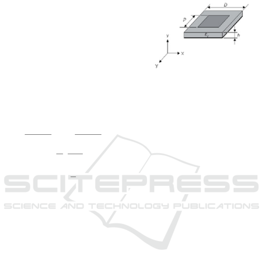
depicted in Figure 1. The square patch size P and the
period D were chosen as the state variables for the
optimization (Dutta, Jayasree , et al. , 2016).
The best approach is to use RF-Shields,
particularly when using the EBG substrate. However,
care must be taken to preserve other crucial elements
impacting the antenna's performance, such as
impedance matching, which offers high efficiency,
shrinks the antenna's size, increases its compactness
and robustness, and integrates with existing RF
circuit component.
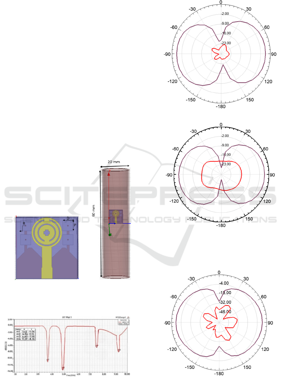
2.2 Simulation Results
The proposed antenna with EBG Structure is shown
in the Figure 2 (a) The antenna is placed at the center
of the esophagus tissue models of the GI tract, as
shown in Figure 2 (b) and corresponding simulations
are carried out to by using HFSS ver. 13.0.
Figure 1: EBG cell under consideration (Kennedy and
Eberhart , 1995)
2.2.1 S- Parameter and Bandwidth
The reflection coefficient (|S11|) of the ingestible
capsule antenna at the center of the esophagus tissue
models of GI tract are exhibited in Figure 3.
The antenna resonates at 3.62 GHz and 4.84 GHz
inside the esophagus, with a reflection coefficient of
-11.01 dB and -13.52 dB respectively.
2.2.2 Radiation Pattern
The 2D far field radiation pattern of the antenna in E-
plane and H-plane inside the oesophagus tissue
models at the resonant frequencies 3.62 GHz and 4.84
GHz are shown in the Figure 4 (a), (b) and Figure 5
(a), (b) respectively. It exhibits an omni-directional
radiation pattern, transmitting information in all
directions. From the radiation pattern, it is obvious
that the antenna exhibits omni-directional radiation
pattern throughout the oesophagus. So the antenna
will be able to transmit information in all directions
independent of the direction and orientation of the
capsule which is essential for ingestible antenna.
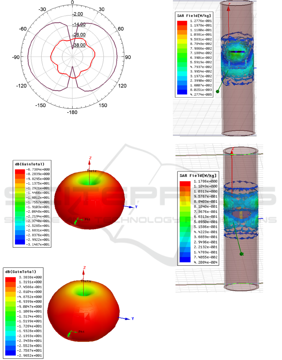
3-D polar plot inside esophagus tissue model for
proposed antenna with EBG is shown in the Figure 6.
Maximum gain is about -28 dB at 4.3 GHz and -29.60
dB at 6.6 GHz.
2.2.3 Specific Absorption Rate (SAR)
The simulated distributions of local SAR averaged
over 10 g tissue when the capsule antenna with EBG
is placed inside esophagus models are shown in the
Figure 7 (a) and (b). IEEE C95.1- 2005 standard
limits 10g-avg SAR is 2 W/Kg and the IEEE C95.1-
1999 standard limits 1g-avg SAR is 1.6 W/Kg. The
maximum SAR is calculated for input power of 1W
through the esophagus averaged over 10g of tissue is
0.127 W/kg at 4.3 GHz and 1.17 at 6.6 GHz. In order
to keep match with IEEE C95.1-2005 standard, the
maximum allowable net input power for the proposed
Optimization and Validation of Microstrip Patch Antenna for Endoscopy Application
199
design of capsule antenna at 3.62 GHz is 854.3 mW
and 736.7 mW at 4.84 GHz. Since Rogers TMM 13i
is a ceramic thermoset polymer composite
(Rogerscorp.com , et al. , 2018), it might be harmless
to the GI tract in case of unexpected disruption of the
capsule.
In summary, achieving a low SAR is essential for
various antenna applications, including wearable or
mobile phone antennas. The EBG structure is a
significant design that can enhance antenna
performance without sacrificing bandwidth.
3 OPTIMIZED MICROSTRIP
PATCH ANTENNA DESIGN
All performance and safety measures of the ingestible
antenna (without EBG) for four different tissue
models of GI tract (esophagus, stomach, small
intestine, and large intestine for two resonant
frequencies are exhibited in Table 2 and all the
performance measures of the ingestible antenna (with
EBG) shown in the Table 3.
(a) (b)
Figure 2: Proposed antenna with (a) EBG Structure (b)
antenna with EBG Structure place in Esophagus tissue
model.
Figure 3: Reflection coefficient frequency responses of the
antenna with EBG in esophagus model.
(a)
(b)
Figure 4: Far-field directivity radiation pattern of the
antenna with EBG at 3.62 GHz through the esophagus
tissue model (a) E – Plane (b) H - Plane
(a)
INCOFT 2025 - International Conference on Futuristic Technology
200
(b)
Figure 5: Far-field directivity radiation pattern of the
antenna with EBG at 4.84 GHz through the esophagus
tissue model (a) E – Plane (b) H – Plane
(a)
(b)
Figure 6: 3-D polar plot of proposed antenna with EBG at
(a) 3.62 GHz and (b) 4.84 GHz
(a)
(b)
Figure 7: Simulated distributions of local SAR averaged
over 1 g tissue for esophagus model at resonant frequency
(a) 3.62 GHz (b) 4.84 GHz
Table 4 shows comparison of SAR reduction by using
EBG Method. There is significant reduction in SAR
values at every stage of GI track. Although because
of the EBG structure there is a slight reduction in
gain, the radiated power and hence radiation
efficiency is in acceptable range which will not affect
the transmission. The fractional BW is not getting
affected much.
Optimization and Validation of Microstrip Patch Antenna for Endoscopy Application
201

4 VALIDATION USING LINK
BUDGET
Using implanted transducers, a biomedical telemetric
link enables remote physiological assessments.
Consequently, a trustworthy channel of
communication is necessary between the patient's
external controlling and/or monitoring equipment and
the in-body device. However, a number of losses,
including route loss, reflection, absorption (Zada and
Yoo , 2018), and polarisation mismatch losses (Shah
and Yoo , 2018), make it difficult to guarantee the
communication link's robustness. We attributed the
highest value of polarisation losses in our connection
analysis to the use of a linearly polarised antenna,
which is capable of changing orientation as it passes
through the GI tract. Additionally, implantable
devices have limited input power and effective
isotropic radiated power (EIRP) to prevent safety
concerns and interference with adjacent devices using
the same frequencies. As a result, for the 402 MHz
and 915 MHz bands, respectively, the EIRP must be
less than or equal to the EIRP
max
= -16 dBm and 36
dBm. Compared to higher frequencies, the signal
travels through the body more consistently at lower
frequencies. Therefore, deep skin implantations and
GI applications are better suited for lower
frequencies. Endoscopic devices may have additional
power limitations due to their electronic circuitry and
batteries than EIRPs (Faisal and Yoo , 2019). The
devices of the endoscopic capsule type employ 20
mW silver oxide batteries, which can constantly
supply the circuit with 3V at 55 mAh for 8–10 hours.
The transmitter power (P
t
), which is less than the
maximum permitted input power (determined using
the maximum SAR values), is kept at -4 dBm in
consideration of these difficulties. Because high data
rates are necessary for capsule endoscopy in order to
transport high-quality images to the external base
station, the value of Br is taken to be 1 Mb/s. In order
for the endoscopic antenna and external device to
create a reliable communication link, the antenna
power (A
p
) must to be greater than the needed power
(R
p
). The following is a method for calculating A
p
and
R
p
values:
A
p
(dB) = P
T x
+ G
T x
+ G
Rx
− L
f
− P
L
, (4)
R
P
(dB) = Eb /N
o
+ KT
o
+ B
r
, (5)
Table 2: Antenna Parameters in Different Tissues at Different frequencies (Without EBG) (1 Watt I/p Power)
Parameters Eso
p
ha
g
us Stomach Small Intestine Lar
g
e Intestine
4.3 GHz 6.6 GHz 4.3 GHz 6.6 GHz 4.3 GHz 6.6 GHz 4.3 GHz 6.6 GHz
|S11|dB -10.76 -15.34 -9.239 -23.55 -6.102 -4.459 -7.17 -5.077
BW
3dB
(
MHz
)
170 760 160 930 140 340 150 390
Fractional
BW (%)
3.96 11.51 3.71 14.13 3.24 5.11 3.48 5.90
Radiation
Efficiency
(
dB
)
6.38 95.65 5.40 96.09 1.27 35.18 5.10 61.43
Maximum
Gain (
d
B)
-13.75 -18 -12.25 -22.15 16.60 -22.25 -11.70 -11.25
Max. SAR
[W/kg]
0.079 40.8 0.0045 7.54 1.368 1050 234 208
Radiated
power
(Mw)
0.430 276.4 0.372 372.01 9.483x10
-
5
234.05 0.388 79.75
Accepted
Power
(
Mw
)
6.738 288.99 6.884 387.12 7.41 665.21 7.60 129.81
Peak
Gain(dBi)
0.108 1.6035 0.0688 1.6794 0.0309 0.6130 0.1389 1.1951
Front to
b
ack ratio
2.385 1.068 1.2529 1.1004 1.4126 1.7683 2.3193 1.4425
Peak
Directivit
y
1.702 1.6764 1.274 1.7476 2.4188 1.7425 2.7225 1.9452
INCOFT 2025 - International Conference on Futuristic Technology
202

Table 3: Antenna Parameters in Different Tissues at Different Frequencies (With EBG) (1Watt I/p Power)
Parameters Eso
p
ha
g
us Stomach Small Intestine Lar
g
e Intestine
f
r
(
GHz
)
3.62 4.84 3.62 4.84 3.62 4.84 3.62 4.84
|
S11
|
dB -3 -3.1 -10 -11.06 -8.06 -8.09 -8.5 -7.01
BW
3dB
(MHz) 700 420 370 360 360 340 370 410
Fractional BW
(
%
)
10.66 9.37 9.67 8.12 7.89 9.89 7.23 8.23
Radiation
Efficiency (%)
12.3 93.12 2.40 26 2.38 26 12.15 22.95
Maximum Gain
(dB)
-28 -29.60 -26.75 -30.30 26.70 -30.30 -27.75 30.25
Max. SAR
[W/k
g
]
0.127
1.78 0.0045 7.45 1.368 2.45 1.06 57..22
Radiated
p
ower
(
mW
)
1.798 24.52 0.325 2.89
0.324
2.89 1.76 2.78
Accepted Power
(mW)
14.56 26.33 13.5 11.14 13.7 11.14 14.5 12.14
Peak Gain(dBi) 0.211 2.18 0.042 0.68 0.043 0.68 0.20 0.61
Front to back
ratio
1.065 1.03 2.56 1.11 2.55 1.11 1.13 1.15
Peak Directivit
y
1.72 2.34 1.77 2.62 1.81 2.62 1.69 2.66
Table 4: Comparison of SAR reduction by using EBG Method
Parameters Eso
p
ha
g
us Stomach Small Intestine Lar
g
e Intestine
f
r
(
GHz
)
4.3 6.6 4.3 6.6 4.3 6.6 4.3 6.6
Max. SAR [W/kg]
Without EBG
0.145 1.17 38.45 59.47 41.34 1050 234 208
Max. SAR [W/kg] With
EBG
0.127 0.198 0.0045 7.54 1.368 25.45 1.06 51.22
Reduction in SAR % 13.79 83.07 99.98 87.32 96.69 97.57 99.54 75.37
where G
Rx
, G
Tx
, and P
Tx
stand for the receiver
antenna's gain, transmitter power, and transmitter
gain, respectively. Receiving antenna is placed on
body near esophagus (approximately 5 cm distance
from transmitting antenna) which is moving through
GI tract. As the transmitting antenna moves
through stomach, small intestine, large intestine the
distance increases. Figure 8 shows the plotted
connection margins for the stomach, large intestine,
and small intestine. Table 5 shows that the value of
G
Tx
varies depending to the implantation scenario,
whereas the value of G
Rx
is thought to be constant at
0.042 dBi. The free space and polarisation mismatch
losses are represented by L
f
and P
L
, respectively. In
general, the distance (d) between the transmitter and
the receiver determines L
f
. The following formulas
can be used to calculate this loss:
L
f
(dB) = 20 log (4πd/ λ ) (6)
In equation (5), the optimal phase shift keying,
temperature, Boltzmann constant, and data rate are
denoted by Eb/N
0
, K, T
0
, and B
r
, respectively.
Table 5: Key factors taken into account for link budget
analysis.
Parameters Value
Resonance frequency f
o
(GHz)
3.62/4.84
Noise power density N
o
(
dB/Hz
)
-203.93
Transmitter power P
Tx
(dBm)
-4.33
Polarization mismatch
loss P
L
(dB)
1
Temperature T
o
(Kelvin) 273
Free space path loss L
f
(
dB
)
Distance dependent
Transmitter antenna gain
G
T x
(
dBi
)
Scenario dependent
Receiver antenna gain G
Rx
(dBi)
0.042
Boltzmann Constant
K
1.38 × 10⁻²³
Available
p
ower A
P
(
dB
)
Distance de
p
endent
Bit rate B
r
(
Mb
p
s
)
1
Required power R
P
(dB) -134.64
Margin A
p
-R
p
(dB) Fig. 8
Optimization and Validation of Microstrip Patch Antenna for Endoscopy Application
203
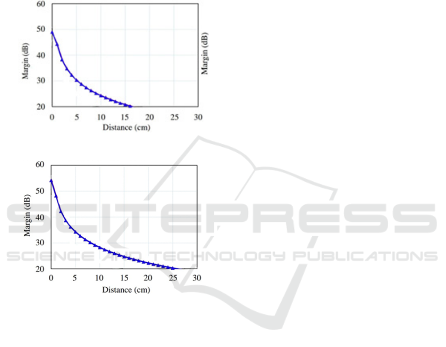
Table 5 contains a list of all the previously
discussed parameters together with their values used
to calculate the connection. The suggested
endoscopic antenna has been shown to reliably
transmit data across a distance of over 25 cm at 20 dB
margins for both frequencies in a variety of implanted
circumstances.
(a)
(b)
Figure 8: Link budget analysis at 1 Mbps in different
implanted organs (a) 3.62 GHz (b) 4.84 GHz.
5 CONCLUSIONS
The Specific Absorption Rate (SAR) is the most
important factor to consider. Because the absorption
of harmful electromagnetic waves can cause serious
injury to the human body. Especially when designing
antennas for wearable technology or cell phones that
come into direct touch with the human body. It is
possible to reduce the SAR value by adjusting a
number of parameters, such as antenna position, size,
and thickness. The EBG substrate is the most
effective method. But when using this method to
reduce the SAR value, it's important to keep in mind
other important factors that affect the antenna's
performance, like impedance matching, which
provides high efficiency, reduces the size of the
antenna, makes it more compact and robust, and
integrates with the existing RF circuit components.
The proposed antenna is only 1.26 percent of the
capsule's volume, measuring 40 mm3 (10 mm × 10
mm × 0.4 mm). The resonant frequencies are around
4.3 GHz and 6.7 GHz, with a -3 dB bandwidth of
roughly 20.4 MHz and 950 MHz, respectively.
Having numerous resonant frequencies has the
benefit of allowing the proposed single antenna to
cover the whole GI system, even if the dielectric
constant changes throughout the GI tract. Different
antennas are required for various GI tracts in the
literature currently under publication. The radiation
pattern is omnidirectional and circularly polarized in
the biological model. The highest recorded radiation
efficiency was 95.65%. Additionally computed for
the purpose of biocompatibility analysis, the GI tract's
SAR value is within the well limit. PSO aids in
lowering the SAR by optimizing the EBG structure's
dimensions. Table VI shows a considerable drop in
SAR values at each level of the GI track. The gearbox
won't be impacted by the EBG structure's little
reduction in gain because the radiated power and,
consequently, radiation efficiency, are within a
reasonable range. The fractional BW is not much
affected. The link budget and SAR analysis were
conducted to ensure the reliability of the wireless link
and user safety, respectively.
6 FUTUTRE SCOPE
Additional body parameters may be included in
channel modelling of communication for more
accuracy purpose.
REFERENCES
R. Mulugu, and C. Saha, “Design, Development and
Realization of UWB Antenna for Wireless Capsule
Endoscopy,” In IEEEInt.Symp. on Antennas & Propag.
(APSYM), pp.19-21, Dec. 2020.
M. Sarestoniemi et al., “WBAN channel characteristics
between capsule endoscope and receiving directive
UWB on-body antennas,” IEEE access, vol. 8,
pp.55953-55968, Mar. 2020.
J. Wang et al., “An Implantable and Conformal Antenna for
Wireless Capsule Endoscopy” IEEE Antennas and
Wireless Propag. Lett., vol. 17, no. 7, pp. 1154-1157,
May 2018.
J. Tarade and U. P. Khot, “Characterization of Microstrip
Patch Antenna for Endoscopy Application” Int. J. of
INCOFT 2025 - International Conference on Futuristic Technology
204

Electronics and Communication Engineering (IJECE),
vol. 11(8), pp. 207-217, August 2024.
S. I. Al-Mously, "Factors influencing the EM interaction
between mobile phone antennas and human head," In
Int. Conf. on Digital Information and Communication
Technology and Its Applications, 2011, pp. 106-120.
P. P. Bhavarthe, S. S. Rathod, and K. Reddy, "A compact
dual band gap electromagnetic band gap structure,"
IEEE Trans. on Antennas and Propagation, vol. 67, pp.
596- 600, 2018.
P. K. Dutta, P. V. Y. Jayasree, and V. S. S. N. S. Baba,
"SAR reduction in the modelled human head for the
mobile phone using different material shields," Human-
centric Computing and Information Sciences, vol. 6,
pp. 1-22, 2016.
J. Kennedy, and R. Eberhart, “Particle swarm
optimization,” In Proc. of ICNN'95- IEEE int.
conference on neural networks, vol. 4, pp. 1942-1948,
Nov. 1995.
Rogerscorp.com, ‘TMM® 13i Laminates’, 2018 [online].
Available:
https://www.rogerscorp.com/acs/products/51/TMM-
13iLaminates.aspx. [Accessed: 10- Jan- 2018].
M. Zada and H. Yoo, “A miniaturized triple-band
implantable antenna system for bio-telemetry
applications,” IEEE Transactions on Antennas and
Propagation, vol. 66, no. 12, pp. 7378–7382, Dec. 2018.
S. A. A. Shah and H. Yoo, “Scalp-Implantable Antenna
Systems for Intracranial Pressure Monitoring,” IEEE
Transactions on Antennas and Propagation, vol. 66, no.
4, pp. 2170–2173, Aprl. 2018.
F. Faisal and H. Yoo, “A miniaturized novel-shape dual-
band antenna for implantable applications,” IEEE
Transactions on Antennas and Propagation, vol. 67, no.
2, pp. 774–783, Feb. 2019.
Optimization and Validation of Microstrip Patch Antenna for Endoscopy Application
205
