
Fault Detection and Power Quality Compensation Using Fuzzy Logic
Based Dynamic Voltage Restorer
Kumari Santosh
1
, Seema Agrawal
1
and Tapesh Yogi
2
1
Department of Electrical Engineering, Rajasthan Technical University Kota, Kota, India
Keywords: Power Quality, Dynamics Voltage Restorer, Fuzzy Logic, Voltage Sag, PI, PID, Voltage Swell.
Abstract: The current vitality situation faces a significant challenge in power quality. With the increasing use of
sensitive hardware, power quality has become a crucial aspect, particularly in terms of input power supply.
Power quality issues can lead to the failure of advanced devices due to unusual current and voltage
frequencies. The primary concern lies in voltage enlargement and dips. A specific system is proposed to
address this issue to prevent voltage enlargement and dips. Modified power equipment, such as Dynamic
Voltage Restorers (DVRs), are employed to resolve this issue. DVRs are advanced, customized control
devices used in power distribution systems, offering advantages like compact size, low cost, and excellent
dynamic response to disturbances. This study presents MATLAB 2021 results for a model based on Fuzzy
Logic (FL) and DVR controllers. FL-based DVR controllers are used in the suggested method to improve the
composite microgrid system's performance. The goal is to develop a faster and more efficient controller than
traditional procedures. The performance will be evaluated using MATLAB simulation tools.
1 INTRODUCTION
Now a days Power distribution lines are crucial for
transmitting electricity over long distances to
consumers. However, these lines are vulnerable to
various hazards, including harsh weather, mechanical
damage, and insulation failure.
Faults in a power system refer to any abnormal
condition that disrupts the normal flow of electrical
current. These faults can occur due to various reasons
such as equipment failure, human error, natural
disasters, or aging infrastructure. Faults can be
classified into several types, including symmetrical
faults, such as three-phase faults, and unsymmetrical
faults, such as phase-to-phase faults, phase-to-ground
faults, and open circuit faults. When a fault occurs, it
can cause a short circuit, leading to an increase in
current flow, which can damage equipment and pose
a risk to human safety. Therefore, it is essential to
detect and clear faults quickly to prevent damage and
ensure the reliable operation of the power system.
This is typically achieved through the use of
protective devices, such as circuit breakers and fuses,
which can detect abnormal conditions and interrupt
the flow of current to prevent further damage.
(Khandakar, Rabbi, et al. , 2024). Fault detection in
power systems is a critical concern for maintaining
system reliability. Consequently, numerous
techniques have been proposed to address this
challenge(Manglik, Li, et al. , 2016).
Increasing power quality by addressing voltage
sags, a prevalent issue within power systems. To
mitigate sags arising from diverse fault scenarios, the
use of a Dynamic Voltage Restorer (DVR) with a
Proportional-Integral (PI) controller is suggested in
the study (Srinivas., Amarendar, et al. , 2024). Power
quality indicators and employs a detection system to
pinpoint faults within distribution networks. The
study emphasizes the system's efficacy in improving
power quality, enhancing fault identification
accuracy, and ultimately bolstering the overall
reliability of power supply (Wanru, He., et al. , 2023).
Dynamic Voltage Restorers (DVRs) are versatile
power devices that can effectively address various
voltage quality issues. By being connected in series
with the power system, DVRs can inject or absorb
reactive power to regulate voltage levels. This paper
provides a comprehensive exploration of DVR
implementation and simulation, with a particular
emphasis on the crucial aspect of switching control
strategy. A pulse width modulation (PWM) scheme is
employed to regulate the output voltage of the DVR,
and detailed results demonstrating its effectiveness
are presented (Rajesh, Mishra, et al. , 2023).
106
Santosh, K., Agrawal, S. A. and Yogi, T.
Fault Detection and Power Quality Compensation Using Fuzzy Logic Based Dynamic Voltage Restorer.
DOI: 10.5220/0013609500004664
Paper published under CC license (CC BY-NC-ND 4.0)
In Proceedings of the 3rd International Conference on Futuristic Technology (INCOFT 2025) - Volume 3, pages 106-113
ISBN: 978-989-758-763-4
Proceedings Copyright © 2025 by SCITEPRESS – Science and Technology Publications, Lda.

DVRs are specialized power devices designed to
counteract voltage sags, swells, and harmonics within
distribution networks. Their construction involves a
combination of power electronic components, control
systems, and energy storage elements. By
strategically injecting or absorbing reactive power,
DVRs effectively mitigate voltage quality issues,
ensuring reliable and efficient power delivery.
Dynamic Voltage Restorers (DVRs) are versatile
power electronic devices used to improve voltage
quality in power systems (Abas, Dilshad, et al. ,
2020). They are particularly effective in addressing
voltage sags, swells, and harmonics, which can
negatively impact the performance of sensitive
equipment. By injecting or absorbing reactive power,
DVRs can maintain voltage levels within acceptable
limits, ensuring reliable and efficient power delivery.
This is especially important in modern power grids
with increasing penetration of renewable energy
sources and sensitive electronic loads (AppalaNaidu,
2016).Fuzzy logic controllers (FLCs) have gained
significant attention from researchers due to their
simplicity and effectiveness in various control
applications, including power converters, motor
drives, and process control. Compared to other
intelligent control techniques(Thaha and Prakash,
2020). FLCs are relatively straightforward to
integrate into systems. This simplicity, coupled with
their ability to provide superior performance
compared to conventional controllers, has made
FLCs a popular choice for a wide range of control
tasks (Elkhateb, Rahim, et al. , 2014).Dynamic
Voltage Restorers (DVRs) often employ Proportional
Integral (PI) controllers to regulate their output.
While effective, PI controllers can be further
optimized by integrating fuzzy logic. Fuzzy logic
enhances the PI controller's adaptability by adjusting
its error and rate of error parameters. This intelligent
approach enables the DVR to perform more
effectively under diverse operating conditions,
surpassing the capabilities of traditional PI controllers
(Saha and Biswas, 2021), (Bhatnagar and Yadav,
2020). A Type-2 fuzzy logic controller is developed
from a Type-1 fuzzy logic controller optimized using
Bee Colony Optimization for engine speed control
(Gurjar, Yadav, et al. , 2020). A shunt active power
filter with a self-tuned harmonic filter and fuzzy logic
controller for harmonic mitigation, reactive power
compensation, and power factor correction (Agrawal,
Sharma, et al. , 2017).
2 PROPOSED DVR
ARCHITECTURE
In a power system, faults can be broadly classified
into two main categories: symmetrical faults and
unsymmetrical faults. Symmetrical faults occur when
all three phases are involved equally, such as a three-
phase fault, which is the most common type of
symmetrical fault. Unsymmetrical faults, on the other
hand, occur when one or two phases are involved.
These include phase-to-ground faults, which occur
when one phase comes into contact with the ground,
phase-to-phase faults, which occur when two phases
come into contact with each other, and phase-to-
phase-to-ground faults, which occur when two phases
come into contact with each other and with the
ground. Additionally, open circuit faults can also
occur, which involve the disconnection of one or
more phases. Each type of fault has distinct
characteristics and effects on the power system, and
understanding these differences is crucial for the
design and operation of protective devices and
systems to detect and clear faults quickly and
efficiently.
Now a days Power distribution lines are crucial
for transmitting electricity over long distances to
consumers. However, these lines are vulnerable to
various hazards, including harsh weather, mechanical
damage, and insulation failure. These factors can lead
to short circuits or shunt faults. Shunt faults can be
classified as symmetrical or unsymmetrical, and
further categorized into ten main types based on the
phases involved (LG, L-L-L, L-L-L-G, L-L). In a
typical power system, faults occur when there is an
abnormal flow of current in an electrical circuit, often
leading to disruptions in power supply and potential
damage to equipment. Accurate and timely detection
of these faults is essential to prevent power outages
and protect connected equipment. Power systems
employ various protection devices, such as relays,
circuit breakers, and fuses to mitigate the impact of
faults. These devices are designed to detect faults,
isolate the affected area, and restore power to the rest
of the system. (Khandakar, Rabbi, et al. , 2024).
Figure 1: Classification of fault in power system
Power System
Fault
Open Circuit
Fault
Short Circuit
Fault
One Conductor
Open
Two Conductor
Open
Three Conductor
Open
Symmetrical
Fault
Unsymmetrical
Fault
Single Line-to-
Ground-Fault
Double Line-to-
Ground Fault
Line-to-Line
Fault
Three Phase
Short Circuit
Fault
Three Phase to
Ground Fault
Fault Detection and Power Quality Compensation Using Fuzzy Logic Based Dynamic Voltage Restorer
107
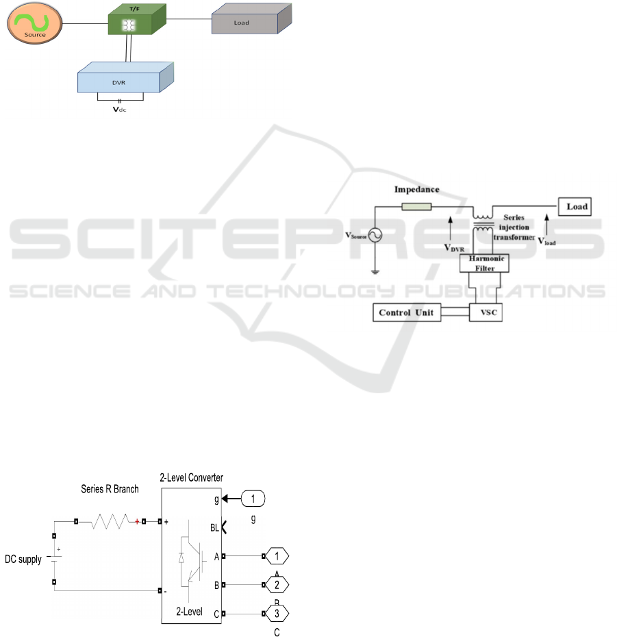
2.1 Dynamic Voltage Restorer (DVR)
A DVR typically consists of four main components:
an energy storage unit, an injection transformer, a
voltage source inverter, and a filtering section.
The
provided image illustrates the operational principle of
a Dynamic Voltage Restorer (DVR), a power
electronic device used to improve voltage quality in
power systems. The DVR consists of several
components, including a source voltage, impedance,
series injection transformer, the DVR itself, a voltage
source converter (VSC), a harmonic filter, and a load.
Figure 2: Schematic Layout of DVR
The DVR system comprises several key
components. These include a storage device for
energy, an injection transformer to interface with the
power system, a voltage source inverter to control
power flow, and a filter to mitigate harmonic
distortion. As given in Figure 1.Power system
disturbances, such as voltage sags and swells, can
significantly impact the reliability and quality of
power supply. Dynamic Voltage Restorers (DVRs)
are a type of Flexible AC Transmission Systems
(FACTS) device that are designed to mitigate these
voltage fluctuations. This paper delves into the
principles of operation, control strategies, and
applications of DVRs in power systems. The paper
also discusses the advantages and limitations of
DVRs, as well as future trends and challenges in their
implementation (Abas, Dilshad, et al. , 2020).
2.2 Block diagram
Figure 3: Circuit diagram of DVR
The given diagram illustrates a 2-level converter
system, which is a key component in various power
electronic applications. The system comprises a
series R branch, a 2-level converter, and a DC supply.
The series R branch consists of a resistor, which is
crucial for controlling the current flow within the
circuit. The 2-level converter is a power electronic
circuit that converts DC power into AC power,
enabling the efficient transfer of energy.
The DC supply provides the necessary input
voltage for the converter. The diagram also includes
a block labelled "g," which likely represents a control
signal that regulates the operation of the 2-level
converter. The numbered blocks (1, 2, 3) might
indicate different switching states of the 2-level
converter, influencing the output waveform.
Overall, this diagram provides a simplified
representation of a 2-level converter system,
highlighting its key components and their
interactions.
2.3 Operation of DVR
Figure 4: Operation of DVR
The Dynamic Voltage Restorer (DVR) operates
on a fundamental principle: it compensates for
voltage disturbances by injecting a compensating
voltage to maintain the desired load voltage.
Specifically, whenever the source voltage
experiences unbalance or distortion, the DVR injects
a voltage of appropriate magnitude to restore the
load-side voltage to its desired amplitude. In essence,
the primary function of the DVR is to continuously
regulate the load voltage waveform. In the event of a
voltage sag or swell, the DVR injects the necessary
voltage to maintain the desired load voltage at the
point of common coupling. Mathematically, the
principle of DVR operation can be represented by the
following equation, which must always be satisfied.
𝑉
𝑆𝑜𝑢𝑟𝑐𝑒
𝑉
𝐷𝑉𝑅
𝑉
𝐿𝑜𝑎𝑑
(1)
INCOFT 2025 - International Conference on Futuristic Technology
108
A DVR consists of a voltage source inverter
(VSI), a coupling transformer, and a control system.
The VSI generates a voltage waveform that is injected
into the power system through the coupling
transformer to compensate for voltage fluctuations.
The control system monitors the system voltage and
generates the necessary control signals to regulate the
output voltage of the VSI (Rajesh, Mishra, et al. ,
2023). DVR control strategies involve detecting
voltage sags/swells and injecting compensating
voltages. Common techniques include proportional-
integral (PI) control for its simplicity, and
synchronous PI decoupling for improved linearity.
The control circuit determines the magnitude,
frequency, and phase shift of the injected voltage,
generated by the power circuit. DVRs can
compensate for both balanced and unbalanced
voltage disturbances, ensuring load voltage remains
within acceptable tolerances. Various control
schemes exist, including energy-optimal, in-phase,
and pre-sag compensation, depending on the specific
requirements and load characteristics.
2.4 Control strategies of DVR
DVR control strategies involve detecting voltage
sags/swells and injecting compensating voltages.
Common techniques include proportional-integral
(PI) control for its simplicity, and synchronous PI
decoupling for improved linearity. The control circuit
determines the magnitude, frequency, and phase shift
of the injected voltage, generated by the power
circuit. DVRs can compensate for both balanced and
unbalanced voltage disturbances, ensuring load
voltage remains within acceptable tolerances.
Various control schemes exist, including energy-
optimal, in-phase, and pre-sag compensation,
depending on the specific requirements and load
characteristics (Bhatnagar and Yadav, 2020). DVRs
combined with fuzzy logic offer a robust and
adaptable solution for power quality improvement.
Fuzzy logic controllers excel at handling
uncertainties and non-linearity inherent in power
systems, making them ideal for DVR control. By
employing fuzzy logic, DVRs can effectively
mitigate voltage sags and swells, dynamically adjust
compensation levels based on real-time system
conditions, and improve overall system stability. This
integration enhances the reliability and efficiency of
power distribution networks, safeguarding sensitive
loads and ensuring uninterrupted power
supply(Thaha and Prakash, 2020).
3 PROPOSED METHODOLOGY
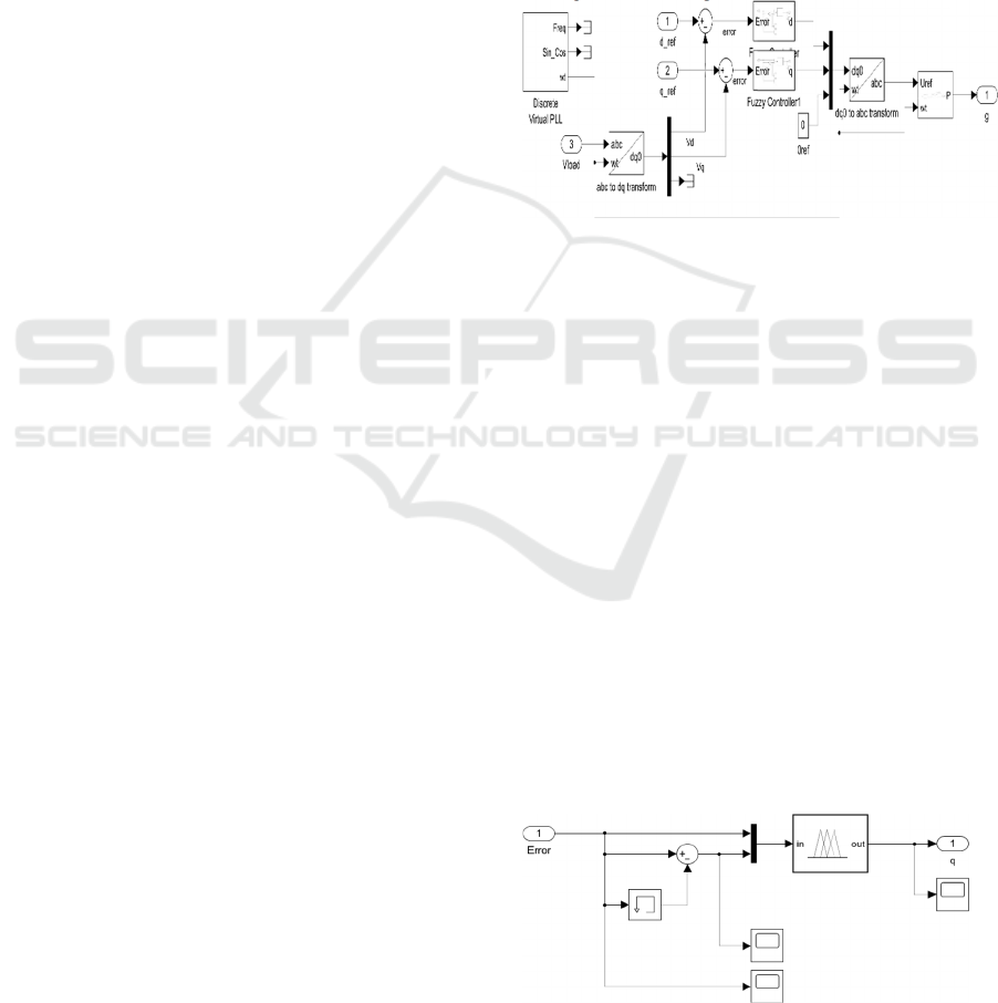
3.1 Fuzzy logic internal circuit
Fuzzy logic controllers (FLCs) have gained
significant attention among researchers due to their
ease of integration with various systems and their
ability to deliver superior performance compared to
conventional controllers. FLCs are particularly well-
suited for applications such as converter control,
motor drives, and process control, where their ability
to handle uncertainty and provide flexible control
strategies is advantageous.
Figure 5: Circuit diagram of fuzzy logic
The test framework suggested in this paper is to
simulate the model for the FL Controller as shown in
Fig.4. The figure illustrates a control system for a
power converter, likely a three-phase inverter.
The system appears to employ a fuzzy logic
controller to regulate the output voltage. The control
system includes a reference generation block, a
Discrete Virtual PLL, a fuzzy controller, and a
transformation block to convert between the abc and
dq reference frames.
The Fuzzy Logic Controller (FLC) operates by
evaluating two inputs at every sampling interval:
error and error derivative. These inputs are then
fuzzified using fuzzy set membership functions and
processed through a set of 'if/then' rules to generate
linguistic or verbal variables. The output of the FLC
is a control signal for each phase, which is defuzzied
and used to regulate the signals. These regulated
signals are then compared with a generated carrier
signal to produce gating pulses for the VSI inverter
(Thaha and Prakash, 2020).
Figure 6: Circuit diagram inside fuzzy logic controller 1
Fault Detection and Power Quality Compensation Using Fuzzy Logic Based Dynamic Voltage Restorer
109

The diagram illustrates a basic feedback control
system. The system starts with an "Error" signal,
which is the difference between the desired output
and the actual output. This error signal is then fed into
a summing junction, where it's combined with
another input signal (not explicitly shown). The
resulting combined signal is then processed by a
Fuzzy Inference System (FIS).
Figure 7: Circuit diagram inside fuzzy logic controller 2
Fuzzy logic controllers (FLCs) have gained
significant attention among researchers due to their
ease of integration with various systems and their
ability to deliver superior performance compared to
conventional controllers. FLCs are particularly well-
suited for applications such as converter control,
motor drives, and process control, where their ability
to handle uncertainty and provide flexible control
strategies is advantageous (Elkhateb, Rahim, et al. ,
2014).
3.2 Fuzzy Logic Control
Fuzzy logic provides a robust and flexible
approach to fault detection in power systems.
Figure 8: MATLAB/SIMULINK fuzzy logic base editor
By employing linguistic terms and fuzzy rules, it
can effectively identify fault conditions, such as short
circuits, open circuits, and unbalanced loads, even in
noise and uncertainties. Fuzzy logic-based systems
can analyse parameters like voltage, current, and
power flow to detect anomalies and trigger
appropriate protective actions. Additionally, it can
handle complex fault scenarios and adapt to changing
system conditions, making it a valuable tool for
ensuring the reliability and safety of power systems
(Gurjar, Yadav, et al. , 2020).
Table 1: Rule matrix
The proposed strategy utilizes linguistic variables
like " negative medium (NM)," "negative small
(NS)," "positive small (PS)," "positive medium
(PM),” Zero (ZE)”, "Big negative (BN)," and "Big
positive (BP)" to define the error and its derivative.
These linguistic variables are associated with
membership functions, which are curves that assign a
membership value between 0 and 1 to each point in
the input space (Elkhateb, Rahim, et al. , 2014).
3.3 Power Quality
Dynamic Voltage Restorers (DVRs) are a
powerful tool for improving power quality in
distribution systems. They rapidly inject voltage
waveforms to compensate for voltage sags,
swells, and interruptions, ensuring a stable and
reliable power supply to sensitive loads. DVRs
are particularly effective in mitigating voltage
fluctuations caused by faults, load switching,
and system disturbances. By rapidly responding
to voltage deviations, DVRs significantly
improve the system's overall power quality,
protecting sensitive equipment and improving
the reliability of power supply (Rajesh, Mishra,
et al. , 2023).
INCOFT 2025 - International Conference on Futuristic Technology
110

4 SIMULATION
To simulate the system, a step load disturbance was
introduced at time 0 to 0.5 second. The simulation
was conducted using MATLAB 2021b-Simulink
software on a computer equipped with an Intel i3 11th
generation processor clocked at 3.00 GHz and 8 GB
of RAM, running Windows 11.
Figure 9: Block diagram of model without DVR
The image depicts a power system with a 3-phase
supply connected to a 3-phase transformer. An LLG
(Line-Line-Ground) fault has occurred somewhere in
the system, represented by the "Fault" block. This
fault creates a direct connection between two phase
conductors and the ground, causing a significant
increase in fault current. The fault disrupts the normal
operation of the loads connected to the system,
including the 3-phase series RLC load and the 3-
phase parallel RLC load. LLG faults can lead to
various consequences, such as damage to equipment,
voltage imbalances, and potential system instability.
Power systems employ various protection schemes,
such as distance protection, differential protection,
overcurrent protection, and ground fault protection, to
detect and isolate LLG faults quickly, minimizing
their impact on the system and ensuring the continuity
of power supply.
Figure 10: Block diagram of model with DVR and fuzzy
logic
The image depicts a power system with a 3-phase
supply connected to a 3-phase transformer. An LLG
(Line-Line-Ground) fault has occurred somewhere in
the system, represented by the "Fault" block. This
fault creates a direct connection between two phase
conductors and the ground, causing a significant
increase in fault current. The fault disrupts the normal
operation of the loads connected to the system,
including the 3-phase series RLC load and the 3-
phase parallel RLC load.
Additionally, the system includes a 12-terminal 3-
phase transformer and a DVR (Dynamic Voltage
Restorer). The DVR is a device used to mitigate the
impact of voltage sags and swells on the system. In
the event of an LLG fault, the DVR can be used to
inject voltage into the system to compensate for the
voltage drop caused by the fault. This can help to
maintain the voltage level at the load and prevent
system instability.
Power systems employ various protection
schemes, such as distance protection, differential
protection, overcurrent protection, and ground fault
protection, to detect and isolate LLG faults quickly,
minimizing their impact on the system and ensuring
the continuity of power supply.
Table 2: Simulink Modelling Parameters
AC Source f
s
= 50 Hz, R
s
= 0.2 ohm, L
s
= .5mH
X-mer 50Hz 11000/400V
Simulation
time
0 to 0.5sec.
RLC Load P= 4.42000 W
Q
L
= (positive var): 100
Q
C
=
(
ne
g
ative var
)
: 0
Three-Phase
Breaker (link)
Switching times : [0.12 0.14]Sec
R
on
: 0.01 Ohm, R
s
: 1e6 Ohm, C
s
:
inf(f)
Block
Parameters:
3-ph
Transformer
12 Terminals
[Three-phase rated power(VA)
Frequency (Hz) = [1.5e3 50]
Winding 1: [V
ph
(Vrms) R(pu)
X(pu)]:
[10 0.00001 0.0003]
Winding 2: [V
ph
(Vrms) R(pu)
X(pu)]:
[100 0.00001 0.0003]
Magnetizing branch: [Rm(pu)
Xm
(p
u
)
]: [200 200]
Three-ph
Source (mask)
(link)
Specify internal voltages for each
phase
V
ph
: 11000 V
rms
Phase angle of phase A : 0 degrees
Frequency (Hz): 50
5 GRAPHICAL RESULTS AND
DISCUSSION
Experimental and simulation results validate the
effectiveness of the proposed system in mitigating
Fault Detection and Power Quality Compensation Using Fuzzy Logic Based Dynamic Voltage Restorer
111

voltage sags within power systems. Under LG, LLG,
and LLLG fault conditions, the integrated DVR and
PI controller consistently demonstrate rapid and
accurate voltage compensation. Voltage profiles are
swiftly restored to acceptable levels, ensuring the
protection of sensitive loads from disruptions. The PI
controller plays a critical role in optimizing the
DVR's response, dynamically adapting to diverse
fault scenarios through a finely tuned compensation
strategy. The system's ability to maintain stability
during fault occurrences is a significant achievement,
highlighting its reliability for practical applications.
The results section will present the outputs
generated by the simulation under various fault
conditions. These outputs have been integrated into a
single body of work to address the simulation's scope
comprehensively.
5.1 With LLG fault
Figure 11: L-L-G Fault Current & Voltage Waveform
5.2 With LLL fault
Figure 12: L- L-L Fault Current & Voltage Waveform
5.3 With LG fault
Figure 13: L-G Fault Current & Voltage Waveform
This power system model focuses on an L-G fault,
representing a single-line-to-ground fault. To
enhance waveform readability, the simulation
duration is set. Assuming a 50 Hz sampling
frequency, the system base voltage for the three-
phase source. Three 3-phase VI measurement blocks
are incorporated within the system. Upon fault
occurrence, the differential relay, with both inputs
connected to the current parameter, detects the abrupt
current surge. This triggers the circuit breaker to
open, isolating the fault i.e., a transient condition. The
waveforms in both figures exhibit a characteristic
spike during the fault. As is well-known, generators
operate asynchronously. However, a rapid fault leads
to an increase in speed and a corresponding current
rise. Concurrently, a significant voltage drop,
approaching zero, and waveform interruptions are
observed during the fault. Similar behaviour is
expected for other fault types.
INCOFT 2025 - International Conference on Futuristic Technology
112

6 CONCLUSION
This presented work focuses on fault identification
and detection using MATLAB Simulink for a 3-bus
power system employing a fuzzy logic controller and
dynamic voltage regulator (DVR). Considering LG,
LLG and LLL faults, a Simulink model is made and
waveforms are obtained.The major problem of power
quality disruptions in modern power networks,
namely voltage swells and sags. Strong solutions
must be used to ensure a consistent and dependable
power supply due to the growing dependence on
delicate electronic devices. In order to do this, this
study suggested a novel method that makes use of
Dynamic Voltage Restorers (DVRs) controlled by
Fuzzy Logic (FL) in a composite microgrid system.
The efficiency of the suggested FL-based DVR
controller in reducing voltage disturbances was
shown by the simulation results produced with
MATLAB 2021. The FL controller performed better
in terms of speed and efficiency than conventional
control techniques. The intrinsic capacity of FL to
manage the uncertainties and nonlinearities present in
actual power systems is responsible for this improved
performance.
REFERENCES
Khandakar, Rabbi, Ahmed., Khandokar, Shadman, Shayer.,
Jahidul, Islam, Shuvo., Fatin, Farhan, Haque., Towfika,
Salam., Shafiun, Miraz., Abdullah, Al, Noman., Md.,
Shohanur, Islam, Sobuj., Muhammad, Yasser, Arafat.,
MD, Istiak, Hasan, Rial. (2024). Enhancing Power Grid
Resilience: Advanced Strategies for Detecting and
Analyzing Faults in Three-Phase Transmission Lines.
1-5. doi: 10.1109/iciteics61368.2024.10625140.
Manglik, W. Li and S. U. Ahmad, "Fault detection in power
system using the Hilbert-Huang Transform," 2016
IEEE Canadian Conference on Electrical and
Computer Engineering (CCECE), Vancouver, BC,
Canada, 2016, pp. 1-4, doi:
10.1109/CCECE.2016.7726627.
N., Srinivas., M, Amarendar, Reddy., M., Shiva, Kumar.,
K, Sruthi. (2024). Power Quality Improvement Using
Custom Power Devices. 1-4. doi:
10.1109/sefet61574.2024.10717912.
Wanru, He., Chunhong, He., Zongjie, Zhang., Bin, Ren.
(2023). Design of Online Intelligent Detection System
for Power Quality and Fault Identification in
Distribution Networks. Applied mathematics and
nonlinear sciences, doi: 10.2478/amns.2023.2.01454.
Saripalli Rajesh*, Mahesh K. Mishra"Design and
Simulation of Dynamic Voltage Restorer (DVR) Using
Sinusoidal Pulse Width Modulation (SPWM) "16th
NATIONAL POWER SYSTEMS CONFERENCE,
15th-17th DECEMBER, 2010 ,pg-317-322.
N. Abas, S. Dilshad, A. Khalid, M. S. Saleem and N. Khan,
"Power Quality Improvement Using Dynamic Voltage
Restorer," in IEEE Access, vol. 8, pp. 164325-164339,
2020, doi: 10.1109/ACCESS.2020.3022477.
AppalaNaidu, T. (2016). The Role Of Dynamic Voltage
Restorer (DVR) in improving power quality. 2016 2nd
International Conference on Advances in Electrical,
Electronics, Information, Communication and Bio-
Informatics
(AEEICB). doi:10.1109/aeeicb.2016.7538259.
H. S. Thaha and T. R. D. Prakash, "Use of Fuzzy Controller
Based DVR for the Reduction of Power Quality Issues
in Composite Micro-Grid," 2020 International
Conference on Renewable Energy Integration into
Smart Grids: A Multidisciplinary Approach to
Technology Modelling and Simulation (ICREISG),
Bhubaneswar, India, 2020, pp. 131-136, doi:
10.1109/ICREISG49226.2020.9174536.
Elkhateb, N. A. Rahim, J. Selvaraj and M. N. Uddin,
"Fuzzy-Logic-Controller-Based SEPIC Converter for
Maximum Power Point Tracking," in IEEE
Transactions on Industry Applications, vol. 50, no. 4,
pp. 2349-2358, July-Aug. 2014, doi:
10.1109/TIA.2014.2298558.
S. K. Saha and S. Biswas, "Fuzzy Logic and PI Controller
Implementation on Dynamic Voltage Restorer," 2021
2nd Global Conference for Advancement in Technology
(GCAT), Bangalore, India, 2021, pp. 1-6, doi:
10.1109/GCAT52182.2021.9587827.
Bhatnagar, M., & Yadav, A. (2020). Fault Detection and
Classification in Transmission Line Using Fuzzy
Inference System. 2020 5th IEEE International
Conference on Recent Advances and Innovations in
Engineering
(ICRAIE). doi:10.1109/icraie51050.2020.9358386.
G. Gurjar, D. K. Yadav and S. Agrawal, "Illustration and
Control of Non-Isolated Multi-Input DC - DC
Bidirectional Converter for Electric Vehicles Using
Fuzzy Logic controller," 2020 IEEE International
Conference for Innovationin Technology (INOCON)
,
Bangluru, India, 2020, pp. 1-5, doi:
10.1109/INOCON50539.2020.9298307.
S. Agrawal, D. Sharma and D. K. Palwalia, "Performance
analysis of SAPF based on self tuned harmonic filter
with fuzzy logic controller," 2017 Recent
Developments in Control, Automation & Power
Engineering (RDCAPE), Noida, India, 2017, pp. 487-
492, doi: 10.1109/RDCAPE.2017.83583
Fault Detection and Power Quality Compensation Using Fuzzy Logic Based Dynamic Voltage Restorer
113
