
Investigation on Crack Propagation Mechanisms in Surrounding
Rock Induced by Excavation Unloading of Deep-Buried Caverns
Donghan Wang
2,3
, Kaiwen Song
2,3
, Qian Dong
1
and Junhong Huang
2,3
1
Hubei Key Laboratory of Blasting Engineering, Wuhan, China
2
Sanya Science and Education Innovation Park, Wuhan University of Technology, Sanya Hainan, China
3
School of Civil Engineering and Architecture, Wuhan University of Technology, Wuhan Hubei, China
Keywords: Rock.Mechanics, Numerical.Simulation, Roadway.Surrounding.Rock, Transient.Unloading, Small-Scale
Surrounding Rock Specimens.
Abstract: To investigate the deformation patterns and failure mechanisms of roadway surrounding rock under transient
excavation unloading, and to simulate the roadway excavation unloading process, a model test system for
roadway excavation and unloading was developed. Multiple sets of jointed rock mass model specimens were
fabricated using high-strength gypsum materials. Numerical simulations were employed to explore the
influences of joint quantity, length, stiffness, and spatial configuration on the failure characteristics of
surrounding rock during excavation unloading. The results indicate that under transient unloading conditions:
Jointed rock masses exhibit a higher degree of failure compared to intact rock masses. Rock masses containing
longer joints demonstrate more pronounced failure phenomena than those with shorter joints. Joint stiffness
exerts relatively minor influence on both peripheral displacement and damage extent of the excavation. Rock
masses with mixed-length joints show greater susceptibility to failure compared to those with uniform-length
joints. Multi-jointed rock masses are more prone to crack formation during unloading, potentially leading to
more significant rock deformation and crack propagation. In contrast, rock masses with fewer joints
experience less impact under such transient unloading conditions, consequently demonstrating enhanced
stability and safety of the surrounding rock.
1 INTRODUCTION
To prevent geotechnical hazards in deep rock mass
engineering, such as roadway instability and
rockbursts, a deeper understanding of the interaction
mechanisms between surrounding rock and support
structures is imperative. Previous studies
predominantly focused on interpreting rock
unloading phenomena through loading theories.
However, stress release induced by roadway
excavation is the primary cause of the loosened zone
in surrounding rock, necessitating consideration of
the mechanical properties of both rock mass and
support structures under varying stress states during
excavation unloading. International research on
excavation unloading commenced earlier. For
instance:(Cai et al., 2007)simulated damage
distribution characteristics in surrounding rock
during deep tunnel excavation using software like
PFC. In China:(Lu et al., 2008)proposed and
validated the concept of transient unloading during
excavation through mechanical analysis and duration
calculations of load release.(Lu et al., 2008) identified
excavation unloading as the primary cause of large-
scale damage zones in surrounding rock.
Research on deep rock mass excavation unloading
characteristics initially focused on classical
theoretical mechanics and numerical simulations,
supplemented by theoretical analyses of practical
engineering issues. Key findings include:(Luo et al.,
2023)analyzed the post-unloading mechanical states
and deformation behaviors of rock masses using
classical mechanics.(Dong et al., 2017)investigated
the impacts of initial in-situ stress, excavation radius,
and dynamic rock strength on unloading-induced
failure and stability.(Dong et al., 2017)demonstrated
that the extent of surrounding rock failure correlates
strongly with unloading duration, with shorter
durations inducing greater disturbance magnitudes.
Instantaneous excavation unloading induces
vibrations and failure in rock masses. Through case
studies, (Fan et al., 2015) and(Lu et al., 2007)found
that larger unloading volumes during excavation
result in stronger vibrations, and transient unloading
366
Wang, D., Song, K., Dong, Q., Huang and J.
Investigation on Crack Propagation Mechanisms in Surrounding Rock Induced by Excavation Unloading of Deep-Buried Caverns.
DOI: 10.5220/0013604600003970
In Proceedings of the 15th International Conference on Simulation and Modeling Methodologies, Technologies and Applications (SIMULTECH 2025), pages 366-373
ISBN: 978-989-758-759-7; ISSN: 2184-2841
Copyright © 2025 by Paper published under CC license (CC BY-NC-ND 4.0)

may amplify the overall vibration response of
surrounding rock.
Current research on dynamic excavation
unloading primarily focuses on the dynamic response
of rock masses. To investigate crack propagation
mechanisms in both jointed and intact rock masses
under excavation unloading, this study designed
laboratory model tests and numerical simulations,
followed by systematic analysis of the results.
2 SIMULATION TEST SYSTEM
FOR LOOSENING OF
UNDERGROUND CAVERN
STRUCTURAL PLANES
UNDER TRANSIENT
EXCAVATION UNLOADING
This section analyzes surrounding rock stress
distribution, introduces a self-developed testing
system, and integrates theoretical-experimental
methodology to establish foundations for subsequent
lab tests.
2.1 Stress Distribution of Roadway
Surrounding Rock
To elucidate the stress distribution of surrounding
rock in semi-circular arched roadways with vertical
walls and predict their failure patterns, the following
analytical approaches are conducted:
The stress distribution of roadway surrounding
rock constitutes a plane strain problem, which can be
solved using the complex variable method (2018; Zhu
et al., 2014; Dai & Zhang, 2012). The in-situ stress
field of semi-circular arched roadways with vertical
walls comprises vertical stress σ
, horizontal
stress σ
, and shear stress τ. The surrounding rock
stress can be expressed by two complex potential
functions:φ(z),and ψ(z).
00
13
0
002
13 0
() () ()
4
1
() ( ) () ()
2
i
z
ze
α
σσ
ϕωξϕξ
ψ
σσ ω
ξψξ
−
+
=+
=− − +
(1)
Parameters 𝜑
(𝜉), 𝜓
(𝜉), and 𝜔(𝜉) in Equation
(1) are determined, while 𝜎
and 𝜎
are assigned
according to Equation (2):
()
()
2
2
0
1
2
2
0
3
2
22
22
arctan 1
22
VH VH
HV
VH VH
HV
VH VH
HV HV
σσ σσ
στ
σσ σσ
στ
σσ σσ
α
ττ
+−
=+ +
+−
=− +
−−
=++
(2)
Consequently, the stress distribution of roadway
surrounding rock is derived as:
()
'
'
'
2''
2'
''
4Re
()
2()() ()
2
()
() ()
i
ρθ
ρθ ρθ
ϕξ
σσ
ωξ
ξ
ω
ξϕξ ψξ
σσ τ
ρωξ
ω
ξ
ω
ξ
+=
−+ = +
(3)
2.2 Introduction to the Test System
To intuitively investigate the deformation behavior of
jointed rock masses during instantaneous excavation
unloading, a simulation test system for transient
unloading-induced loosening of structural planes in
underground caverns was designed. The system
operates as follows:
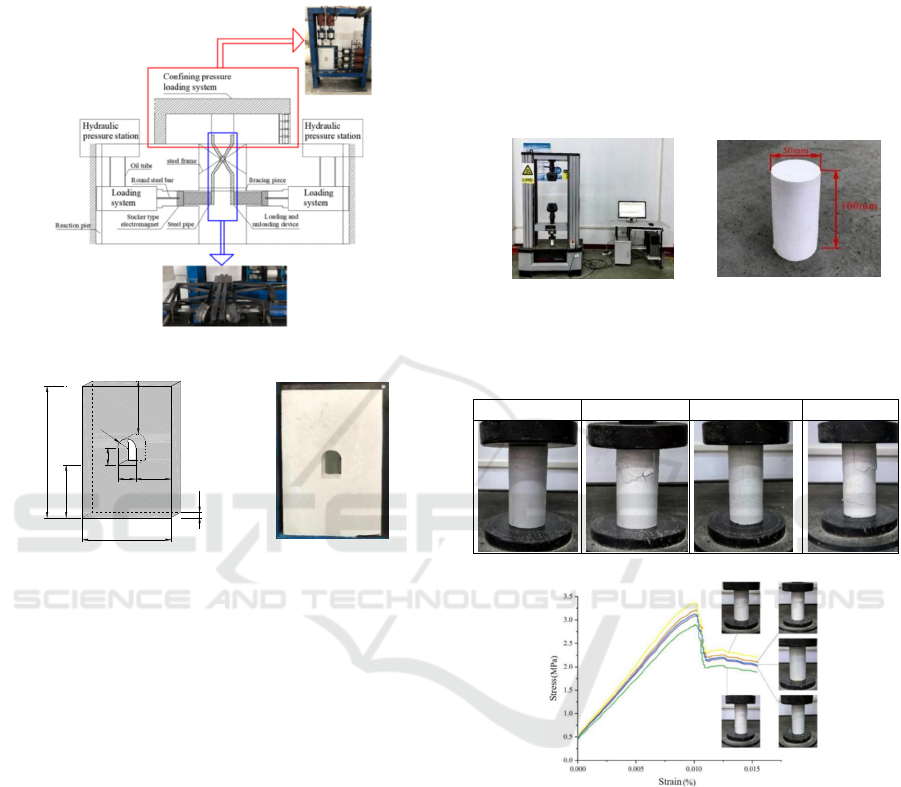
(I) Mechanical Configuration
The front end of a lever-type loading/unloading
assembly is embedded into the pre-excavated slot
within the surrounding rock model (containing
structural planes) and tightly contacts the slot
wall.The rear end is connected to a suction-cup
electromagnetic actuator via a welded cylindrical
steel tube.
(II)Unloading Simulation Process
Under axial tensile loading, the lever mechanism
applies controlled interfacial pressure to the slot wall
in the chamber assembly. Deactivating the
electromagnetic actuator triggers instantaneous
pressure release, simulating transient stress-field
unloading (Figure 1). This system facilitates lab-scale
simulation of excavation loading/unloading cycles,
with the lever mechanism enabling instantaneous
structural plane unloading in pre-excavated models
through controlled energy storage/release.
In terms of material selection, gypsum is adopted
for rock mass modeling due to its ease of processing,
customizable composition, and cost-effectiveness.
Gypsum-based materials remain widely utilized in
dynamic rock experiments. Dimensions and physical
characteristics of the surrounding rock specimens are
detailed in Figure 2.
The model incorporates centrally positioned pre-
existing cracks with mica sheets embedded along
vertically penetrating surfaces to simulate primary
Investigation on Crack Propagation Mechanisms in Surrounding Rock Induced by Excavation Unloading of Deep-Buried Caverns
367
structural planes in surrounding rock. A roadway
excavation of standardized geometry is implemented
at the specimen's center to improve real-world
scenario simulation fidelity.
Figure.1: Schematic diagram of simulation test system.
24
R
4
8
10
8
60
16
24
40
(a)Gypsum specimen model
size drawing
(b)Physical diagram of
the plaster specimen
F
igure.2: Size drawing and physical drawing of surroundin
g
r
ock specimen.
3 DESIGN OF LABORATORY
TESTS FOR TRANSIENT
UNLOADING DURING
DEEP-BURIED CAVERN
EXCAVATION
3.1 Uniaxial Compressive Strength
Testing of Gypsum
Gypsum was selected as the surrounding rock
simulation material for subsequent tests. To
determine the compressive strength of the gypsum
material used in the tests, uniaxial compression tests
were conducted using a 50 kN microcomputer-
controlled electronic universal testing machine
(Figure 3). The standard cylindrical specimens
(Figure 4) measured 50 mm in diameter and 100 mm
in height. A loading rate of 5 mm/min was applied to
ensure complete acquisition of stress-strain curves.
Photographs of five specimens before and after
failure are summarized in Table 1, with
corresponding stress-strain curves presented in Fig. 5.
Accounting for material heterogeneity and
experimental errors, the average uniaxial
compressive strength and elastic modulus of the
gypsum material were determined as 3.92 MPa and
5.77 GPa, respectively. This section must be in two
columns.
F
igure 3: Physical diagram
of experimental equipment.
Figure 4: Dimensions o
f
test standard parts.
Table 1: Typical photographs of standard gypsum
specimens before and after uniaxial compression failure..
Pre-failure Post-failure Pre-failure Post-failure
Figure 5: Stress-strain curves of gypsum specimens.
3.2 Experimental Methodology
The simulation test system (Section 2.1) applied 2
MPa confining pressure with instantaneous unloading
(≤0.5s). Mica-embedded gypsum specimens with
variable joint geometries (quantity/length/
orientation) simulated excavation-induced structural
planes. Fourteen test groups (Table 2) captured
systematic crack propagation patterns near
discontinuities, providing empirical validation for
structural plane evolution mechanisms under
excavation unloading disturbances.
SIMULTECH 2025 - 15th International Conference on Simulation and Modeling Methodologies, Technologies and Applications
368
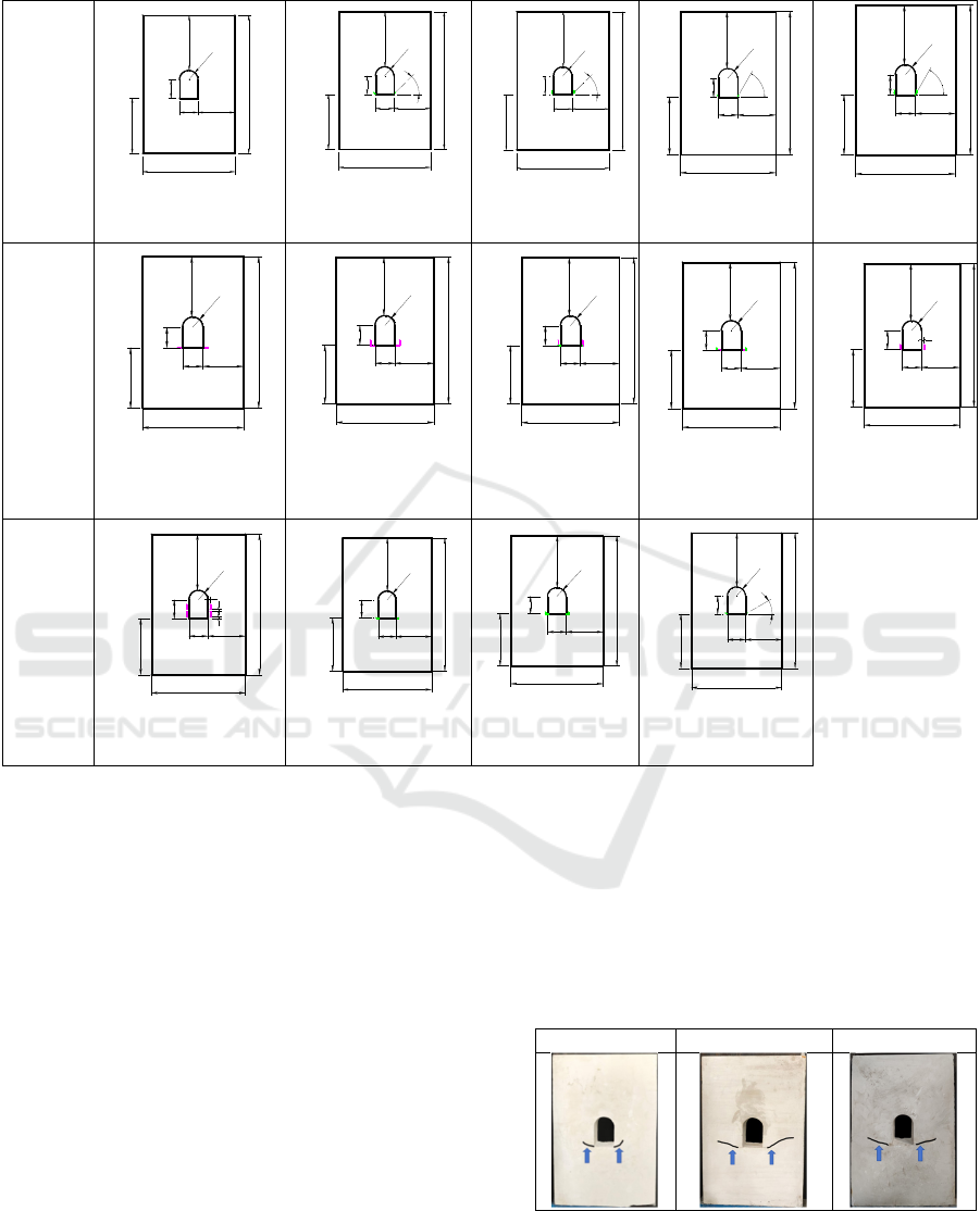
Table 2: Schematic diagram of test conditions.
Schematic
Diagram
Test Case 1 (Without
mica sheets)
Test Case 2 (Two 1
cm mica sheets)
Test Case 3 (Four 1
cm mica sheets)
Test Case 4 (Two 1
cm mica sheets)
Test Case 5 (Four 1
cm mica sheets)
Schematic
Diagram
Test Case 6 (Two 2
cm mica sheets)
Test Case 7 (Four 2
cm mica sheets)
Test Case 8
(Two 1cm and two
2cm mica sheets)
Test Case 9 (Two 1
cm and two 2 cm
mica sheets)
Test Case 10
(Two 2 cm mica
sheets)
Schematic
Diagram
Test Case 11 (Four 2
cm mica sheets)
Test Case 12(Two 1
cm mica sheets)
Test Case 13(Four
1 cm mica sheets)
Test Case 14(Two 1
cm mica sheets)
3.3 Analysis of Recorded Experimental
Phenomena
Post-test documentation and analysis of gypsum
failure characteristics were conducted as follows:
3.3.1 Failure Characteristics of Intact and
Jointed Rock Masses
A comparative analysis of intact rock masses (Test
Case 1) and jointed rock masses (represented by Test
Cases 6 and 12) before and after testing is presented
in Table 3. To enhance visibility of experimental
phenomena, crack trajectories in the images were
manually highlighted with black lines to accentuate
fine fractures that were otherwise difficult to discern.
Experimental observations showed intact rock
under high confining pressure exhibited plastic
deformation with gradual microcrack development
and eventual fracture, while sudden unloading
induced elastic recovery that reduced plasticity and
accelerated crack dilation. In contrast, jointed rock
masses demonstrated reduced integrity due to pre-
existing discontinuities, causing localized stress
concentrations and accelerated crack propagation
under equivalent loading, resulting in extended cracks
and more pronounced failure phenomena.
Table 3: Phenomena of unjointed rock mass and partially
jointed rock mass after failure.
Test Case 1
Test Case 6
Test Case 12
24
8
40
24
8
R
4
60
16
4
5
¡
ã
R
4
60
16
40
24
8
24
8
4
5
¡
ã
40
24
8
60
16
R
4
24
8
24
8 16
6
0
¡
ã
40
24
8
R
4
60
24
8 16
6
0
¡
ã
40
24
8
60
R
4
40
24
8
60
24
8 16
R
4
40
24
8
60
R
4
24
8 16
60
R
4
24
8 16
40
24
8
R
4
24
8 16
40
24
8
60
24
8 16
40
24
8
1
60
R
4
40
24
8
1
11
60
24
8 16
R
4
24
8
40
24
8
R
4
60
16
24
8
R
4
60
16
40
24
8
R
4
3
0
¡
ã
60
16
40
24
8
24
8
Investigation on Crack Propagation Mechanisms in Surrounding Rock Induced by Excavation Unloading of Deep-Buried Caverns
369
3.3.2 Failure Characteristics of Jointed
Rock Masses with Varying Properties
(I)Different Joint Lengths
Comparative analysis indicates 2 cm-jointed rock
masses exhibit longer post-unloading cracks than 1
cm-jointed counterparts due to reduced transient
stress concentrations near joint planes in shorter joints,
enhancing stability and limiting crack propagation.
Table 4: Diagram of post-failure phenomena at different
joint lengths.
Test Case 7
Test Case 8
Test Case 9
Table 5: Diagram of post-failure phenomena at different
joint lengths.
Test Case 6
Test Case 12
Mixed-length joints exhibit compound transient
failure: longer joints initiate fracturing as shorter
joints amplify damage, reducing safety margins
versus uniform joints during dynamic excavation (
Table 4, Table 5).
(II)Different Joint Dip Angles
Table 6 documents failure progression in specimens
with 1 cm mica sheets at 30°,45°,60° dip angles
(Cases 2/4/14) under transient unloading. Mica sheets
are spatially indexed per Figure 6 for precise damage
characterization.
Comparative analysis of Test Cases 2, 4, and 14
revealed that under identical joint lengths and
transient unloading conditions: Cracks exhibited
comparable lengths and predominantly propagated
along joint planes. Increasing joint dip angles resulted
in steeper crack trajectories (i.e., greater angles
relative to the horizontal).
Figure 6: Schematic diagram of the naming of mica sheets.
Table 6: Diagram of the phenomenon after failure at
different joint dip angles.
Test Case 2
Test Case 4
Test Case 14
Test Cases 3/5/13 (Table 7) with four mica sheets
each demonstrated that steeper dip angles of No.②
mica sheet (45º/60º/0º) inversely correlated with No.
① mica sheet proximity to excavation boundaries
(Case 13>3>5). Post-test analysis revealed crack
coalescence between mica sheets and excavation
boundaries in Case 5 but no crack initiation along No.
① sheet in Case 13. Proximity to excavations reduces
confinement, enabling transient unloading-induced
crack formation, while distant fractures under higher
confinement exhibit suppressed crack initiation/
propagation.
Table 7: Diagram of the post-failure phenomenon of
different joint dip angles.
Test Case 3
Test Case 5
Test Case 13
(III)Different Joint Numbers
Table 8: Phenomena after failure of different joint quantities.
Test Case 10
Test Case 11
SIMULTECH 2025 - 15th International Conference on Simulation and Modeling Methodologies, Technologies and Applications
370
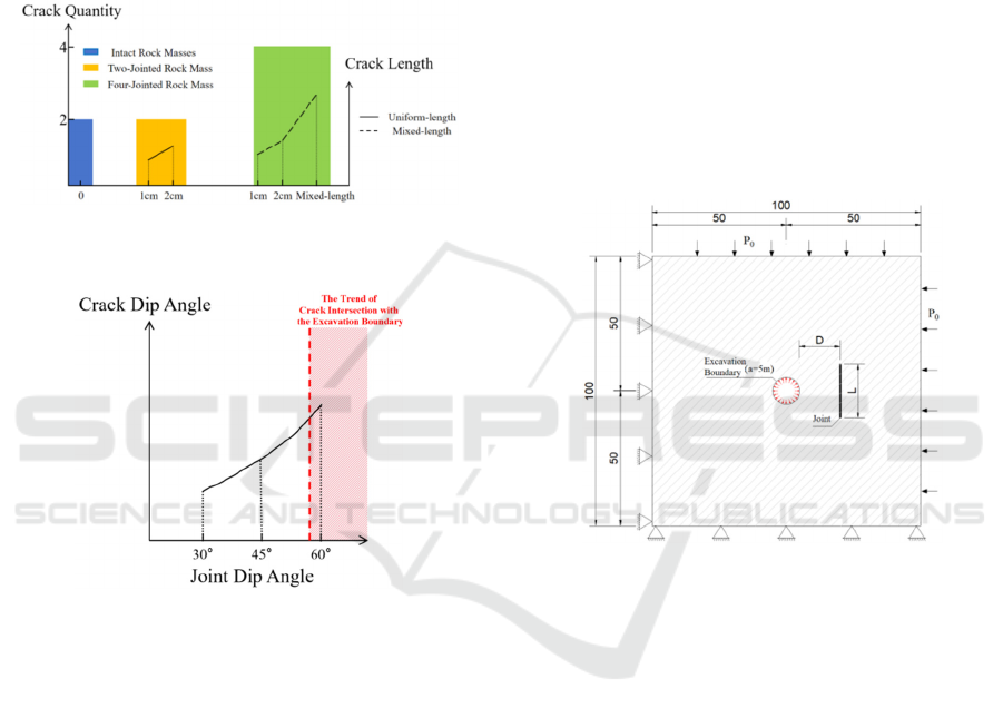
Table 8 demonstrates crack-joint quantity
proportionality: Multi-jointed systems near
excavation boundaries undergo simultaneous joint
propagation-deformation-cracking processes under
transient unloading, where adjacent joint interactions
amplify rock deformation/crack coalescence,
substantially destabilizing rock masses. Fewer-joint
configurations exhibit diminished joint interplay and
unloading sensitivity, yielding superior
stability/safety through restricted crack development.
Figure 7: Correspondence Between Joint and Crack
Dimensions: Lengths and Quantities.
Figure 8: Relationship between Joint Dip Angles and Crack
Trajectories.
Experimental results (Figures 7, 8) demonstrate
intact rock masses generate fewer cracks than jointed
counterparts under transient unloading. Increased
joint quantity directly elevates crack numbers in
single-length jointed systems. Equivalent joint
quantities show steeper Joint #② dip angles position
Joint #① closer to excavation boundaries, promoting
crack-boundary intersection and potential crack
multiplication. Single-length joints exhibit
proportional crack length-to-joint size relationships,
while mixed-length systems develop complex stress
redistribution enabling extended crack propagation.
Joint quantity, geometric orientation, and spatial
arrangement collectively govern transient unloading-
induced crack evolution and instability mechanisms.
4 NUMERICAL SIMULATION OF
TRANSIENT UNLOADING
DURING DEEP-BURIED
CAVERN EXCAVATION
Existing studies on jointed rock transient unloading
primarily addressed joint geometry/spatial
configurations, overlooking joint material
heterogeneity. This chapter employs finite element
analysis with an implicit-explicit-implicit sequential
method to investigate deformation-damage
mechanisms in surrounding rock during transient
unloading, including systematic analysis of unloading
rate effects.
4.1 Model Establishment
Figure 9: Schematic Diagram of Transient Unloading
Model for Jointed Rock Masses.
The jointed rock mass model (100 m × 100 m)
features a central excavation cavity (a=5 m) for
simulating excavation-induced transient unloading.
Plane strain conditions are enforced through
displacement constraints on front/rear surfaces, with
peripheral non-reflective boundaries for wave
reflection suppression. A 40 MPa global load
simulates in-situ stress. Initial equilibrium is
established by applying radial confinement
equivalent to in-situ stress at cavity periphery (t=0),
followed by linear unloading to 0 MPa to replicate
blasting-induced transient stress release. The
geometric configuration and staged loading protocol
are illustrated in Figure 9.
Investigation on Crack Propagation Mechanisms in Surrounding Rock Induced by Excavation Unloading of Deep-Buried Caverns
371
4.2 Influence Mechanisms of Joint
Stiffness on Surrounding Rock
Deformation and Damage During
Transient Unloading
Subsequent numerical simulations focus on the
damage and deformation characteristics of
surrounding rock under varying joint stiffness
conditions. In practical engineering, rock masses
typically contain both persistent and non-persistent
joints. However, this study exclusively addresses
non-persistent joints, as under high in-situ stress
conditions, joints are predominantly closed, with
normal stiffness values generally ranging between
kn=0.05E and kn=0.2E (2018; Zhu et al., 2014; Dai
& Zhang, 2012). Accordingly, joint normal stiffness
values are set to kn =0.05E, 0.10E, 0.15E, 0.20E, and
0.25E, while tangential stiffness is fixed at 20% of the
normal stiffness (ks=0.2kn).
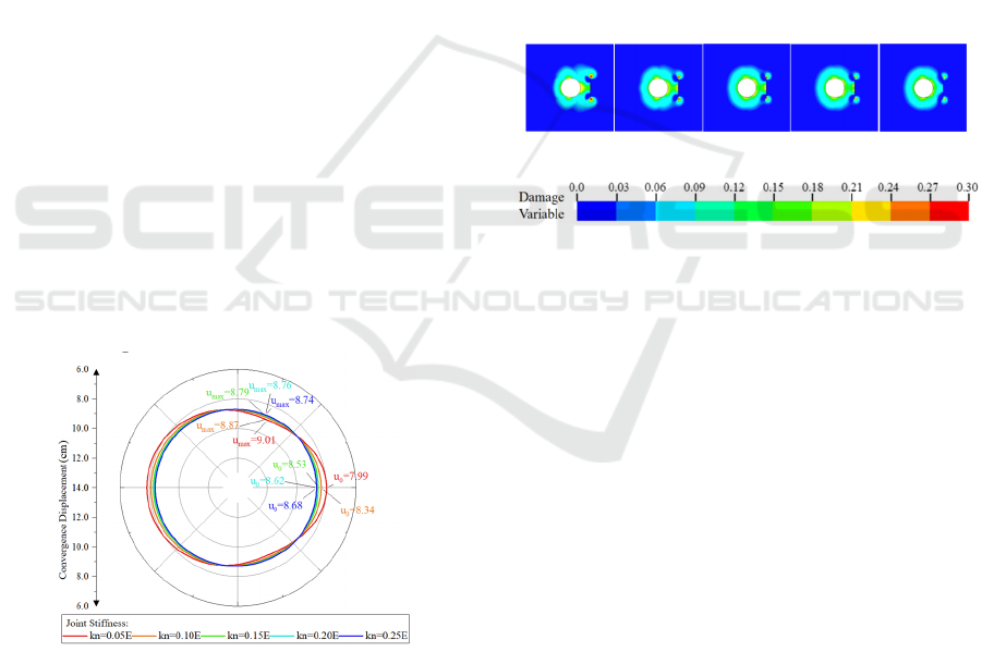
Figure 10 clearly illustrates the influence of joint
stiffness on cavern convergence displacement in
short-joint configurations, showing that under short-
joint conditions, the maximum convergence
displacements occur within the 70 º -80 º sector
relative to the cavern, with a slight reduction (0.27
cm) as joint stiffness increases from kn =0.05E to
kn=0.25E. Notably, an anomalous displacement
behavior is observed along the horizontal axis closest
to the joints, where convergence displacement
increases by 0.70 cm during the same stiffness
escalation, indicating a counterintuitive stiffness-
dependent response.
Figure 11: Peripheral Displacement Diagrams of Cavern
under Different Joint Normal Stiffness.
The influence of joint stiffness on damage
evolution is also significant, as demonstrated in
Figure 1, which presents damage contours of short
joints under varying joint stiffness conditions. As
joint stiffness increases, stress wave reflection
diminishes, leading to a reduction in the displacement
differential between reflection and incidence zones.
Consequently, the damage severity at joint tips
decreases markedly, with the damage zone extent
shrinking significantly and gradually disconnecting
from the cavern periphery. Similarly, the damage
intensity near the cavern, particularly on the side
adjacent to the joints, is notably reduced with
increasing joint stiffness due to weakened reflection
effects.
Joint stiffness exerts relatively minor influence on
peripheral displacement and damage. When kn
increases from 0.05E to 0.25E, the maximum
convergence displacement decreases by only 0.27cm,
while damage zones at joint tips transition from
persistent to non-persistent states. In joint support
design, a "zoning control strategy" should be adopted:
implementing stiffness reinforcement in main
displacement zones while coordinating flexible
supports in near-field horizontal regions to create
mechanical buffer belts.
kn=0.05E kn=0.10E kn=0.15E kn=0.20E kn=0.20E
Figure 12: Damage Contours of Surrounding Rock under
Different Joint Stiffness Conditions.
5 CONCLUSIONS
The self-developed roadway surrounding rock
excavation unloading model test system was
employed to simulate instantaneous failure of
surrounding rock during tunnel excavation, yielding
the following conclusions:
(1) Model tests revealed that both intact and jointed
rock masses develop inverted “八 ”-shaped cracks
under excavation unloading. Compared to intact rock
masses, prefabricated jointed rock models exhibit
more pronounced crack propagation.
(2) When multiple joints of equal length exist in a
single model, the number of formed cracks aligns
closely with the original prefabricated joint count.
Longer prefabricated joints result in longer final crack
lengths.
(3) Rock mass models containing prefabricated joints
with varying lengths and dip angles demonstrate
significant uncertainty in the quantity, length, and
SIMULTECH 2025 - 15th International Conference on Simulation and Modeling Methodologies, Technologies and Applications
372

orientation of final cracks, necessitating further
systematic investigation.
(4) The coupled "damage suppression-displacement
excitation" effect induced by joint stiffness on
surrounding displacement and damage of
underground chambers reveals the dual attributes of
rock mass structural stiffness parameters.
ACKNOWLEDGEMENTS
This work is supported by the Foundation of Hubei
Key Laboratory of Blasting Engineering
(No.BL2021-13), the National Natural Science
Foundation of China (Grant No. 52108368, No.
52109165), the Fundamental Research Funds for the
Central Universities (WUT: 2024IVA028).
REFERENCES
2018, Некоторые основные задачи математической
теории упругости. In H. Zhao, T. Fan, & C. Wang
(Eds.), Beijing: China Science Publishing& Media Ltd.
Cai, M., Kaiser, P. K., Morioka, H., Minami, M., Maejima,
T., Tasaka, Y. & Kurose, H. (2007). FLAC/PFC
Coupled Numerical Simulation of AE in Large-scale
Underground Excavations. International Journal of
Rock Mechanics and Mining Sciences, 44(4), 550-564.
http://doi.org/ 10.1016/j.ijrmms.2006.09.013
Dai, J. & Zhang, L. (2012). Shuxue Wuli Fangcheng
[Shuxue Wuli Fangcheng]. Southeast University Press.
Dong, C., Zhao, G., Li, Y., Meng, X., Lu, X. & Zhang, L.
(2017). Mechanical properties and failure mechanism
of Surrounding Rocks in Deep Circular Tunnel under
Excavation Unloading [Mechanical properties and
failure mechanism of surrounding rocks in deep circular
tunnel under excavation unloading]. Journal of Mining
and Safety Engineering, 34(3), 511-518, 526
Fan, Y., Lu, W., Yang, J., Yan, P. & Chen, M. (2015).
Attenuation Law of Vibration Induced by Transient
Unloading During Excavation of deep Caverns
[Attenuation law of vibration induced by transient
unloading during excavation of deep caverns]. Rock
and Soil Mechanics(2), 541-549. http://doi.org/10.
16285/j.rsm.2015.02.033
Lu, W. (1996). A Study on Interaction between Stress wave
and Slipping rock Interface [A Study on Interaction
between stress wave and slipping rock interface]. Rock
and Soil Mechanics(3), 70-75.
Lu, W, Zhou, C., Chen, M., Jin, L. & Yan, L. (2008).
Research on Transient Characteristics of Excavation
Unloading [research on transient characteristics of
excavation unloading]. Chinese journal of rock
mechanics and engineering, 27(11), 2184-2192. http://
doi.org/10.3321/j.issn:1000-6915.2008.11.003
Luo, S., Yan, P., Lu, W., Dong, Z., Zhou, C., Yang, Z. &
Hu, Y. (2023). Stability Index of Surrounding Rock
during Deep Rock Excavation Considering Energy
Release Speed. Applied sciences, 13(5), 3000. http://
doi.org/10.3390/app13053000
W. Lu, M. Chen, P. Yan, & C. Zhou. (2007). Study On
Vibration Characteristics of Surrounding rock Induced
by Tunnel Excavation under high in-situ stress [study
on Vibration Characteristics of Surrounding rock
induced by Tunnel Excavation under High in-situ
stress]. chinese journal of rock mechanics and
engineering, 26(z1), 3329-3334. http://doi.org/10.
3321/j.issn:1000-6915.2007.z1.111
Yan, P., Lu, P., & Xu, H. (2007). A Primary Study to
Damage Mechanism of Initial Stress Dynamic
unloading when Excavating Under high geostress
condition [A primary study to damage mechanism of
initial stress dynamic unloading when excavating under
high geostress condition]. Explosion and Shock
WAVES, 27(3), 283-288. http://doi.org/10.3321/j.issn:
1001-1455.2007.03.016
Yang, J. (2014). Coupling Effect of Blasting and Transient
Release of In-situ Stress during Deep Rock Mass
Excavation [ Doctor, Wuhan University].
Zhu, J., Yang, J., Shi, G., Wang, J. & Cai, J. (2014).
Calculating method for conformal mapping from
exterior of unit circle to exterior of cavern with arbitrary
excavation cross-section [Calculating method for
conformal mapping from exterior of unit circle to
exterior of cavern with arbitrary excavation cross-
section]. Rock and Soil Mechanics(1), 175-183.
Investigation on Crack Propagation Mechanisms in Surrounding Rock Induced by Excavation Unloading of Deep-Buried Caverns
373
