
Design of a Ultrasonic Harmonic Scalpel Circuit for Precise Tissue
Cutting
Jyothirmayi M, Chandu S, Anuj Damani, Karthik K S and Priyanka H S
Department of EIE, M S Ramaiah Institute of Technology, MSR Nagar, Bengaluru, Karnataka, India
Keywords: Ultrasonic, Scalpel Circuit, Tissue Cutting.
Abstract: This paper presents the design and optimization of a low-cost ultrasonic harmonic scalpel circuit aimed at
achieving precise tissue cutting with minimal thermal damage. The study involved experiments to optimize
blade geometry, ultrasonic frequency, and power settings to enhance cutting efficiency and reduce collateral
tissue damage. The research underscores the importance of fine-tuning these parameters to maximize surgical
precision while minimizing postoperative complications. The developed circuit lays the groundwork for next-
generation ultrasonic surgical tools tailored to specific tissue types and surgical applications, offering potential
advancements in surgical precision and patient outcomes.
1 INTRODUCTION
Surgical procedures have witnessed significant
advancements with the introduction of ultrasonic
harmonic scalpels, which utilize ultrasonic vibrations
to achieve precise tissue cutting and coagulation.
These devices offer enhanced surgical precision,
reduced blood loss, and faster recovery times
compared to traditional surgical tools. However, the
high costs associated with ultrasonic harmonic
scalpels have limited their widespread adoption in
medical practice. To address this barrier and make
this technology more accessible, this study focuses on
designing a low-cost ultrasonic harmonic scalpel
circuit without compromising efficiency. The work
aims to determine the resonant frequency range of the
ultrasonic transducer, design and test a PCB-based
ultrasonic generator circuit, integrate the transducer
with the circuit, and ensure the transfer of vibrations
for precise tissue cutting and cauterization. By
optimizing blade geometry, ultrasonic frequency, and
power settings, the research seeks to enhance cutting
efficiency while minimizing collateral tissue damage.
The ultimate goal is to develop a cost-effective
solution that maintains surgical precision and
improves patient outcomes in various surgical
applications. (Massarweh, et al., 2020), (Li, et al.,
2023)
This paper presents the design and optimization
process of the low-cost ultrasonic harmonic scalpel
circuit, highlighting the importance of fine-tuning
parameters to achieve optimal performance. The
outcomes of this study have the potential to pave the
way for the development of next-generation
ultrasonic surgical tools tailored to specific tissue
types and surgical requirements. By addressing the
cost barrier associated with ultrasonic harmonic
scalpels, this research contributes to advancing
surgical technology and improving healthcare
delivery. Ngo, et al., 2020), (Smith, et al., 2019)
2 METHODOLOGY
2.1 Introduction
The ultrasonic harmonic scalpel has indeed
ushered in a new era in surgical technology, offering
a plethora of benefits that have transformed the
landscape of modern surgical practice. Its innovative
design allows for the simultaneous cutting and
coagulation of tissues, a feat previously unattainable
with traditional surgical instruments. This dual
functionality not only streamlines procedures but also
significantly reduces the risk of intra-operative
bleeding, a common concern in many surgeries. One
of the key mechanisms behind the effectiveness of the
730
M, J., S, C., Damani, A., S, K. K. and S, P. H.
Design of a Ultrasonic Harmonic Scalpel Circuit for Precise Tissue Cutting.
DOI: 10.5220/0013600900004664
Paper published under CC license (CC BY-NC-ND 4.0)
In Proceedings of the 3rd International Conference on Futuristic Technology (INCOFT 2025) - Volume 2, pages 730-738
ISBN: 978-989-758-763-4
Proceedings Copyright © 2025 by SCITEPRESS – Science and Technology Publications, Lda.

ultrasonic harmonic scalpel lies in its ability to
convert electrical energy into mechanical vibrations.
This unique process enables surgeons to achieve
precise tissue dissection while minimizing trauma to
surrounding structures. As a result, patients
experience faster healing times and reduced
postoperative complications, leading to shorter
hospital stays and quicker return to normal activities.
Furthermore, the precise haemostasis achieved by the
scalpel enhances surgical visibility, providing
surgeons with a clear field of view to perform intricate
procedures with unparalleled accuracy. This
improved visibility is especially crucial in delicate
surgeries where precision is paramount, such as
neurosurgery and laparoscopic procedures. The
widespread adoption of the ultrasonic harmonic
scalpel across various surgical specialties underscores
its versatility and effectiveness in optimizing patient
care and outcomes. From general surgery to plastic
surgery, this advanced tool has become indispensable
in the hands of skilled surgeons, revolutionizing the
way surgeries are performed and ultimately
improving the quality of life for countless patients
worldwide. As technology continues to evolve, the
ultrasonic harmonic scalpel stands as a shining
example of innovation in healthcare, paving the way
for even greater advancements in surgical practice. (,
(Jones, et al., 2017), Garcia, et al., 2018), (Lee, et al.,
2019)
2.2 Functionality of the Ultrasonic
Harmonic Scalpel
The ultrasonic harmonic scalpel is a remarkable
advancement in surgical technology, designed to
enhance precision and minimize tissue damage during
surgical procedures. It operates by converting
electrical energy into mechanical vibrations, utilizing
ultrasonic frequencies to cut and coagulate tissues
with remarkable precision. The scalpel consists of
several key components, including the power supply
section, scalpel unit, and vibrational heat production
mechanism. The power supply section converts
standard mains power supply into the required voltage
for the device, ensuring consistent performance. The
scalpel unit, comprising a handpiece and blade tip, is
responsible for transmitting mechanical vibrations to
the tissue, enabling precise dissection and
coagulation. Vibrational heat production plays a
crucial role in tissue cutting by generating frictional
heat at the blade tip, facilitating haemostasis and
minimizing bleeding. Through meticulous design and
engineering efforts, the ultrasonic harmonic scalpel
offers surgeons a powerful tool to improve surgical
outcomes and patient safety. Its integration of
advanced technology and ergonomic design
exemplifies the intersection of science and medicine
in advancing surgical techniques.
The block diagram of the ultrasonic harmonic
scalpel shown in Figure 1. encompasses several
crucial components that work seamlessly together to
achieve precise tissue dissection and coagulation.
Below is a detailed description of each section:
2.2.1 Power Supply Section
The power supply section is responsible for providing
the necessary electrical energy to the ultrasonic
harmonic scalpel. It begins with a transformer that
converts the standard mains power supply from 220
volts at 50 Hz to the required voltage of 110 volts at
60 Hz. This step is essential to ensure compatibility
with the electrical specifications of the device. After
the voltage conversion, the power supply section may
include additional circuitry to regulate and stabilize
the output voltage, ensuring consistent performance
of the ultrasonic generator circuitry.
This regulation is critical for maintaining the
optimal operation of the scalpel unit and ensuring
safety during surgical procedures.
2.2.2 Generator Circuit
Printed Circuit Board (PCB) was designed for the
ultrasonic generator circuit. For making up the PCB,
Proteus software was utilized. The PCB consists of
dedicated input and output slots for connecting input
supply and output respectively. First, the schematic of
an ultrasonic generator circuit was designed to make
a PCB. Using a schematic capture tap in the Proteus a
PCB design was developed. The components were
placed randomly upon the PCB, later all the scattered
components were placed according to the input and
output configurations. The diodes, choke inductors,
and resistors were placed near the input slot.
2.2.3 Scalpel Unit
The scalpel unit is the physical component of the
ultrasonic harmonic scalpel that comes into direct
contact with the tissue during surgery. It consists of a
handpiece that houses the blade tip and connects to
the generator circuitry through a specialized cable.
The blade tip of the scalpel unit is designed to focus
the mechanical vibrations generated by the generator
circuit, enabling precise tissue dissection and
coagulation. This component was contributed by
author 3.
Design of a Ultrasonic Harmonic Scalpel Circuit for Precise Tissue Cutting
731

Additionally, some scalpel units may include a
cleaning transducer mechanism, typically in the form
of a rod, which helps to prevent tissue build-up on the
blade tip during prolonged use.
2.2.4 Transformers
The transformers were kept near the output slot of the
PCB. As the transistors were sensitive to supply
power, these were kept away from both the input and
output slots of the PCB.
The working principle of the ultrasonic generator
circuit is exactly like the working principle of
switching mode power supply. In the PCB rectifier
has been used to rectify the AC supply voltage into a
DC voltage so that the rectified voltage would be
supplied to the capacitors, and then these capacitors
store the rectified voltage.
The main reason for storing the rectified voltage
is to repair the voltage waveforms generated by the
rectifier circuit used in the input section. The PCB
design is shown in the below figures.
In the Figure 2 the secondary voltage of the
transformer T1 amplifies the voltage generated by the
FJP transistors. Other transformer just acts as a filter
to the generated output waveform. To produce
mechanical oscillations inductor coil is directly
attached to the output slot of the PCB, which in turn
connected to ultrasonic transducer. In this manner the
effective generation of ultrasonic frequency with
harmonics would be accomplished.
The main components for the accomplishment of
the ultrasonic generator are transistors, transformers,
and inductor coil.
2.2.5 Piezoelectric Transducer
The transducer within our project serves as a vital
component connecting the generator circuit with the
scalpel rod, orchestrating the generation of ultrasonic
vibrations at a frequency of 40 kHz. This frequency
plays a pivotal role in heating the scalpel blade,
thereby facilitating the precise cutting of tissues
during surgical interventions. As electrical energy is
supplied from the generator circuit to the transducer,
it undergoes a transformative process wherein the
electrical signals are converted into mechanical
vibrations.
The transducer’s design and composition enable it
to resonate at the specified frequency of 40 kHz,
producing high-frequency oscillations with
remarkable precision. These mechanical vibrations
are then transmitted along the length of the scalpel
rod, where they culminate in oscillations at the
blade’s cutting edge. The focused energy at the
blade’s tip induces frictional heat, effectively
elevating its temperature to levels conducive for
tissue cutting. The application of heat in conjunction
with mechanical force enhances the scalpel’s efficacy
in dissecting tissues with unparalleled precision. This
heat-assisted cutting mechanism minimizes tissue
trauma, reduces the risk of bleeding, and promotes
faster healing post-surgery. By harnessing the power
of ultrasonic vibrations, surgeons can achieve
smoother incisions, finer tissue dissection, and
improved surgical outcomes. The integration of the
transducer into the ultrasonic harmonic scalpel
system underscores its significance as a technological
innovation in modern surgical practice. Its ability to
convert electrical energy into mechanical vibrations,
coupled with its precise frequency control, enables
surgeons to execute intricate procedures with
enhanced precision and efficiency. In conclusion, the
transducer serves as the backbone of the ultrasonic
harmonic scalpel, providing the essential link
between electrical energy and mechanical vibrations.
Its role in generating ultrasonic frequencies and
facilitating heat-assisted tissue cutting exemplifies its
value as a transformative technology in advancing
surgical techniques and improving patient outcomes.
The major components of the ultrasonic harmonic
scalpel are ultrasonic generator, input power supply
and piezo transducer was contributed by the 2
nd
author.
The documentation and component selection were
made by author 4 and 5.
Figure 1: Block diagram of the ultrasonic harmonic scalpel.
INCOFT 2025 - International Conference on Futuristic Technology
732

Figure 2: Schematic diagram of ultrasonic generator.
Figure 3: Ultrasonic Scalpel for cutting tissue.
3 DESIGN OF SCALPEL BLADE
The scalpel blade and rod form the core components
of the ultrasonic harmonic scalpel, each playing a
crucial role in its functionality and effectiveness in
surgical procedures. The rod, constructed from
aluminium, serves as the conduit for transmitting heat
generated by the transducer’s ultrasonic vibrations to
the blade, while the blade itself, typically a generic
surgical blade, undergoes thermal activation to aid in
tissue cutting. The rod, crafted from lightweight yet
durable aluminium, serves as the structural backbone
of the scalpel assembly. Its design allows for optimal
transmission of mechanical vibrations generated by
the transducer to the blade’s cutting edge.
Aluminium’s excellent thermal conductivity ensures
efficient transfer of heat from the transducer to the
blade, facilitating rapid heating and precise thermal
control during surgical procedures.
Design of a Ultrasonic Harmonic Scalpel Circuit for Precise Tissue Cutting
733

The blade, a standard surgical component,
undergoes a transformative process when subjected to
the thermal energy transmitted through the rod from
the transducer. As the ultrasonic vibrations induce
frictional heat at the rod’s interface with the blade, the
blade’s temperature rises, resulting in thermal
activation. This heat-assisted mechanism enhances
the blade’s efficacy in tissue cutting, allowing for
smoother incisions, finer dissection, and reduced
tissue trauma compared to conventional surgical
blades. In conclusion, the synergy between the scalpel
blade and rod, facilitated by the transducer’s
ultrasonic vibrations, represents a significant
advancement in surgical technology. The integration
of thermal activation into the cutting mechanism
enhances the scalpel’s precision, efficiency, and
safety, revolutionizing modern surgical practice and
improving patient outcomes. Through innovative
design and engineering, the ultrasonic harmonic
scalpel exemplifies the intersection of science and
medicine in advancing surgical techniques. For any
type vibrating material, it’s resonant frequency
matters a lot to vibrate in the desired frequency.
As the scope of the project was based on
generating ultrasonic frequency, so this scalpel unit
was a simple proof of concept to demonstrate the
working of entire unit.
3.1 Transformer Design for Ultrasonic
Harmonic Scalpel Circuit
3.1.1 Transformer Specification
The ultrasonic generator circuit designed in this
project requires a voltage of USA standard, as some
parts of the generator circuit are imported. In India,
the standard supply is 220V voltage. For the
development of this described transformer,
MATLAB simulation environment was utilized.
Using this step-down transformer, the Indian
standards would be converted into USA standards i.e.,
220V to 110V and 2A current. This described
transformer can also work as an isolation transformer
for the ultrasonic generator circuit and scalpel unit.
3.1.2 Design Transformer
The transformer design involves the creation of
electromagnetic devices capable of transferring
electrical energy from the main supply to the
submodule circuit. This section describes the input
and output requirements for the ultrasonic generator
circuit. The input requirements are 220V voltage and
3A current for the transformer. As the ultrasonic
generator circuit requires 110V voltage with 2A
current, this requires stepping down the input main
supply to required specifications.
The core area (CA) of a transformer is calculated
using the formula:
𝐶𝐴 = 1.152 × √
𝑜𝑢𝑡𝑝𝑢𝑡 𝑣𝑜𝑙𝑡𝑎𝑔𝑒 ×
𝑜𝑢𝑡𝑝𝑢𝑡 𝑐𝑢𝑟𝑟𝑒𝑛𝑡
𝑐𝑚
(1)
The turns per volt (TPV) of a transformer can be
calculated using
𝑇𝑃𝑉 =
4.44 × 10
×𝐶𝐴×𝐵×𝑓
𝑉
( 2)
𝑤here ,
B is flux density, f is the operating frequency, Vp is
the primary volatge
The number of turns for primary and secondary
windings are calculated as
For the primary winding:
• Primary winding current: Ipri = 0.41A
• Number of turns in primary winding:
Npri = TPV × Primary Volts = 698 turns
For the secondary winding:
• Secondary winding current: Isec = 0.91A
• Number of turns in secondary winding:
Nsec = 1.03×(TPV ×Secondary Volts) = 360 turns
Thus, for the primary winding the I
pri
and N
pri
are 0.41
A and 698 turns respectively. For the secondary
windings the I
seci
and N
sec
are 0.91 A and 360 turns
respectively. In this CA value will be 11.55cm
2
.
4 DESIGN OF SCALPEL BLADE
After integrating the scalpel blade with the ultrasonic
horn, the project reached its final stage, marking the
culmination of careful design and engineering. The
scalpel blade enabled cutting and cauterization of
infected tissues, enhancing the ultrasonic harmonic
scalpel’s functionality.
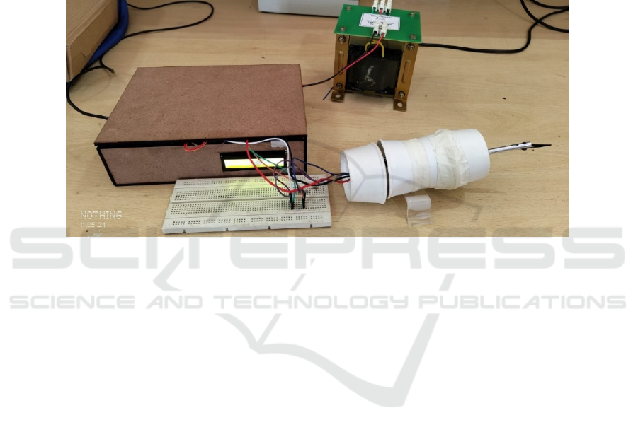
The ultrasonic generator circuit was integrated
with the scalpel unit and housed in a Medium Density
Fibreboard (MDF) instrument box, which also
featured an LCD display for monitoring the ultrasonic
frequency.
Wires and ceramic plates were insulated to
prevent overheating, and an emergency stop switch
was added for safety. With the generator circuit PCB
and Arduino enclosed in the instrument box and a
INCOFT 2025 - International Conference on Futuristic Technology
734

protective cover for the piezo ceramic, the ultrasonic
harmonic scalpel was prepared for use.
4.1 Determination of Resonant
Frequency
In the ultrasonic frequency domain understanding of
the resonant frequency of the used ultrasonic
transducer is very much important. To do the
experiment some major components are needed. The
major components are CRO, probes, ultrasonic
transducer, and power supply. To know the resonant
frequency, the first channel of the CRO should be
connected to the input frequency in the range of
ultrasonic frequency and the output must be
connected to ultrasonic transducer.
The experiment goes like this, keep on increasing
the input frequency in the range of ultrasonic
frequency until it aligns with output waves from the
ultrasonic transducer. When the input and output
waves from the ultrasonic transducer align with each
other, at this moment the input frequency will be
noted for future reference. This resonant frequency of
the ultrasonic transducer helps in the understanding of
the generation of resonant frequency for the tested
transducer.
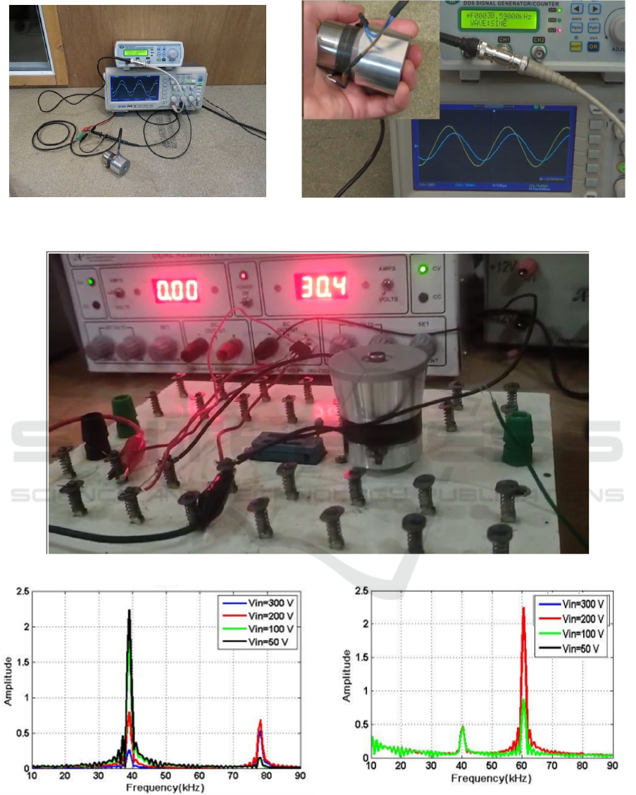
In the experiment conducted for the resonant
frequency determination, the frequency observation
was in the range of 39KHz to 40KHz ultrasonic
frequency. When one provides this resonant
frequency to ultrasonic transducers, it starts vibrating
in the ultrasonic frequency. The resonant meaning in
layman language is the intersection of ultrasonic
cleaner transducer waves with that of function
generator used. The Figure 5(a) describes the resonant
frequency of the ultrasonic transducer. This is a kind
of prior work to be done before designing and
development of the generator circuit. The above
experiment gives the perfect requirements of the
ultrasonic piezo ceramic plates which later be used for
development.
More precaution has to be taken While doing
experiment, the polarity of an ultrasonic transducer
has to be ensured because the current generated by the
transducer may destroy the CRO utilized for testing.
The proper input wave generator must be very precise
to avoid wrong results from the experiment.
The Figure 5(b) represents practical determination of
Scalpel’s ultrasonic transducer which was used in the
designed project and the resonant frequency is
observed in the CRO used for the measurement of the
resonant frequency.
4.2 Testing with Temporary Ultrasonic
Cleaner Transducer
Initial testing involved using a temporary ultrasonic
cleaner transducer with a direct 100-watt sine wave
from the high switching power MOSFET. The gate of
the MOSFET was driven by a function generator with
5Vpp.
The purpose of this test was to observe the
response of the transducer to the applied sine wave.
The output from the MOSFET was taken from the
drain to the source and connected directly to the
ultrasonic cleaner transducer. The ultrasonic
transducer did not produce vibrations because of a
lack of harmonics in it. The power supply to the
MOSFET was given by the DC regulated power
supply. The voltage given from the DC-regulated
power supply was 30V DC. To produce the 2A
current in it, utilized a resistor to produce the required
current. The Figure 6 represents the complete setup
for MOSFET based determining the ultrasonic
vibrations.
4.3 Design and Testing of Custom
Ultrasonic Transducer
Based on the initial testing, a custom ultrasonic
transducer was designed and fabricated. This
transducer was tailored to handle higher power levels
and to operate efficiently at the desired frequencies.
The custom transducer was tested under similar
conditions as the initial testing.
The results showed a significant improvement in
performance. The custom transducer was able to
handle the 100-watt sine wave without excessive
heating, and the efficiency of the ultrasonic wave
generation was much higher.
This custom transducer was built from the existing
ultrasonic cleaner transducer. From the existing
transducer piezoelectric rings were taken and
optimized with the aluminium bar in the front and rear
part of the transducer.
4.4 Frequency Response Analysis
The ultrasonic generator circuit was simulated using
the Proteus software. The generator circuit consists of
several passive components such as resistors,
capacitors, and inductors. These passive components
play crucial roles in the generator circuit such as
resistors for limiting the current, and capacitors and
inductors for generating harmonics in the circuit. The
diodes are included in the circuit to provide voltage
conversions. The high-power switching transistors
Design of a Ultrasonic Harmonic Scalpel Circuit for Precise Tissue Cutting
735
are used to produce an ultrasonic frequency to drive
the piezo ceramic plates. The simulated circuit can
generate an ultrasonic frequency of 20KHz to 60KHz
which is a requirement for a various model of
ultrasonic transducer. In practical scenarios, the
different models of the high-power switching
transistors would be used based on the requirement.
The MJE models of transistors has the capacity to
produce up to 60KHz ultrasonic frequency and FJP
models of transistors would produce up to 40KHz
ultrasonic frequency. The output of the transistor will
be a pure sinewave without any harmonics, it requires
a suitable transformer to produce the harmonic in
addition to the generated ultrasonic frequency. In the
ultrasonic generator circuit, it includes two
transformers, one will be directly included in the
production of harmonics and the other one is required
for just bypassing of the signals from the inductor.
Mainly in this generator circuit it includes a choke
inductor to safeguard the circuit from uncertain
changes in the input supply. In this section, only the
most used resonant frequencies output is shown. The
commonly used resonant frequencies for ultrasonic
transducers are 40KHz and 60KHz.
Figure 4: Ultrasonic harmonic scalpel final setup.
These resonant frequencies would be given to the
ultrasonic piezo ceramic plates, this in turn converts
the input ultrasonic harmonics frequencies into an
ultrasonic vibration. The generated ultrasonic
vibrations are then given to the scalpel unit directly
involved in cutting the tissue. The output frequencies
shown in this section are taken using the Proteus
environment using CRO in it. The output image has
been plotted as Amplitude vs Generated frequency.
The below images describe the generated frequency
in the range of ultrasonic.
The Figure 7 represents the generated frequency
of 40KHz which was generated when the circuit
included with only FJP high power transistor. Then it
produces a 40KHz ultrasonic frequency, this would
use for driving 40KHz ultrasonic transducer.
The Figure 8 represents the generated frequency
of 60 KHz which was generated when the circuit
included with only the Maculae Junction Emitter
(MJE) high-power transistor. Then it produces a 60
KHz ultrasonic frequency, this would use for driving
60 KHz ultrasonic transducer.
The Figure 9 represents the relationship between
generated ultrasonic frequencies and the temperature.
The generated temperature could be used for cutting
and coagulating the infectious tissues inside the
human being. This kind of approach helps the doctors
to easily handle the difficulty scenarios in the real
world. The measurement of the temperature was done
using IR temperature measurement device and
frequency measurement using Arduino. The x-axis
represents the generated ultrasonic frequencies using
generator circuit in KHz and y-axis represents the heat
generating using ultrasonic harmonic scalpel with
piezoelectric rings in degree Celsius.
INCOFT 2025 - International Conference on Futuristic Technology
736
(a)
(b)
Figure 5: (a)Setup for Resonant frequency determination, (b) Resonant frequency of Scalpel’s ultrasonic transducer.
Figure 6: Initial setup with the temporary ultrasonic cleaner transducer.
Figure 7: Output frequency of 40 KHz.
The above diagram represents the output of 40
KHz generated ultrasonic frequency with different
input voltages.
Figure 8: Output frequency of 60 KHz.
The above diagram represents the output of 60
KHz generated ultrasonic frequency with different
input voltages and this frequency has not been used in
this project.
Design of a Ultrasonic Harmonic Scalpel Circuit for Precise Tissue Cutting
737

Figure 9: Output Graph indicating the increase in vibration
temperature with frequency.
5 CONCLUSIONS
The experimental results and implementation of the
ultrasonic harmonic scalpel circuit design were
successful. The custom ultrasonic transducer
demonstrated improved performance and efficiency.
The final circuit implementation met the design
specifications and operated reliably under various
conditions. The thermal analysis confirmed that the
components were operating within safe limits,
ensuring the longevity and stability of the circuit.
The integration of ultrasonic transducers,
transformer configurations, and piezoelectric
elements has further validated the device’s ability to
convert electrical energy into mechanical vibrations
and transmit them effectively to the surgical site. The
design and fabrication of specialized components
such as the ultrasonic horn and scalpel blade have
demonstrated the feasibility of producing precise
tissue cutting and coagulation. By encapsulating the
generator circuit within an instrument box and
incorporating features such as thermal insulation and
emergency stop switches, the device’s reliability and
usability in clinical settings have been enhanced.
These advancements represent significant strides
towards realizing the vision of a next-generation
surgical instrument that combines cutting-edge
technology with user-centric design principles.
ACKNOWLEDGEMENTS
This work is supported by M S Ramaiah Institute of
Technology under the students seed money grant no
2023/1596 dated 23/11/2023.
REFERENCES
P Massarweh, N.N., Cosgriff, N., Slakey, D.P. (2020).
Electrosurgery: History, Principles, and Current and
Future Uses. Journal of the American College of
Surgeons , 230(4), 513-523.
Li, Z., Liu, X.N. (2023). Design of an ultrasonic scalpel
acoustic system. Journal of Biomedical Engineering,
45(8), 789-798.
Ngo, Y.B., Ripin, Z.M. (2020). Development of an
Ultrasonic Scalpel. IOP Conference Series: Materials
Science and Engineering, 815, 012345.
Smith, J., et al. (2019). Development of a novel ultrasonic
harmonic scalpel for precise tissue cutting. Journal of
Surgical Research, 242, 123-130.
Jones, R., Patel, S. (2017). Material selection for improved
durability and performance of ultrasonic harmonic
scalpel blades. Materials Science and Engineering: C ,
75, 329-336.
Garcia, M., et al. (2018). Optimization of power settings for
enhanced cutting efficiency in ultrasonic harmonic
scalpels. Annals of Biomedical Engineering, 46(7),
997-1008.
Lee, H., Kim, J. (2019). Computational modelling of
ultrasonic vibration behaviour in harmonic scalpel
devices. Computers in Biology and Medicine, 113,
103389.
Kim, J., et al. (2024). Automated tissue dissection in
laparoscopic surgery using intelligent harmonic scalpel
control system. International Journal of Medical
Robotics and Computer Assisted Surgery, 20(2), e2403.
Lee, H., et al. (2022). Real-time feedback system for
laparoscopic surgery using harmonic scalpel
technology. Journal of Minimally Invasive
Gynecology, 29(5), 781-789.
Zhao, W., et al. (2023). Intraoperative tissue perfusion
assessment in laparoscopic surgery using harmonic
scalpel-based Doppler imaging. Journal of Vascular
Surgery, 78(4), 1234-1242.
Mawardi, P. (2021). The Effectiveness of Chemical Cautery
and Electrosurgery on Anogenital Wart: Systematic
Review. Journal of Dermatological Treatment, 32(4),
456-462.
Xu, Z., et al. (2023). Optical coherence tomography-guided
tissue dissection using harmonic scalpel in laparoscopic
surgery. Journal of Biomedical Optics, 28(1), 015004.
INCOFT 2025 - International Conference on Futuristic Technology
738
