
Enhancement of Transient Stability Performance Using UPFC with
PSS in Large Power Network
Kalyani A. Bangde
1a
, Vedashree P. Rajderkar
1b
, Vinod K. Chandrakar
1c
and Shyam D. Bawankar
2d
1
Dept. of Electrical Engineering, G H Raisoni College of Engineering Nagpur, India
2
Dept. of Electronics Engineering, G H Raisoni College of Engineering Nagpur, India
Keywords: Transient Stability, MATLAB, PSS and UPFC
Abstract: The ever-increasing load demand in today massive power networks has made operation planning essential. A
relatively new transmission technology called Flexible AC Transmission systems is widely utilized to
improve power grid stability, maintain bus voltage levels and decrease flows on heavily laden lines. This
study looks into how UPFC can improve the operation of major power networks. The performance of the
power network is enhance by the Unified Power Flow Controller, which regulates the power tide across the
network. Additionally, the Power System Stabilizer (PSS) is an excitation controller that supplements
damping. In order to handle voltage fluctuations and transient stability concerns, the study focuses on
integrating the UPFC into the power system model and using its PI controller. MATLAB/SIMULINK was
used to design and test the system. Using the UPFC the suggested system may minimize rotor speed deviation
(∆ω), stability rotor speed (ωn) and swiftly dampen out oscillations caused by defects. Additionally, it
improves the system real power, reactive power and node voltage profile more efficiently than a system
without a UPFC and PSS. The outcome show notable gains in oscillation damping capabilities and power
system performance.
1 INTRODUCTION
The increasing capacity of interconnected power
networks in contemporary transmission line systems
is driving up the demand for electricity. The power
system must run efficiently and dependably to
guarantee a steady supply of electricity to satisfy the
expanding needs of contemporary civilization.
Advanced technologies are becoming more and more
necessary to improve system performance as power
grids get more complicated and linked. The usage of
Flexible AC Transmission Systems devices, such as
the Unified Power Flow Controller has been made
possible by recent developments in power electronic
devices. These devices improve controllability and
boost the electrical networks capacity to transport
power. Additionally, electro-mechanical oscillations
are dampened by the Power System Stabilizer (PSS),
a
https://orcid.org/0009-0003-0895-2575
b
https://orcid.org/0000-0002-3630-1417
c
https://orcid.org/0000-0002-0912-7281
d
https://orcid.org/0009-0005-5184-1517
a supplemental excitation controller. A power system
stabilizer is a control system that lessens oscillations
in the generator rotor angle hence increasing power
system stability. Transient stability is crucial for
power system design and operation in the face of
noteworthy interruptions like faults and switching
lines. Transient stability mentions to the system
capacity to quickly revert to a stable condition when
the load changes. The regulation of real and reactive
power flow, rotor speed, rotor speed deviation and
voltage at system buses within transmission power
system networks areas just a few of the topics that
have been the subject of current UPFC simulation
studies utilizing MATLAB software. A survey of
important articles in this field is provided below, with
references.
In a study published in 2006 (Chandrakar,
Kothari, et al. , 2006), Chandrakar et al. examine the
Bangde, K. A., Rajderkar, V. P., Chandrakar, V. K. and Bawankar, S. D.
Enhancement of Transient Stability Performance Using UPFC with PSS in Large Power Network.
DOI: 10.5220/0013599300004664
Paper published under CC license (CC BY-NC-ND 4.0)
In Proceedings of the 3rd International Conference on Futuristic Technology (INCOFT 2025) - Volume 2, pages 635-641
ISBN: 978-989-758-763-4
Proceedings Copyright © 2025 by SCITEPRESS – Science and Technology Publications, Lda.
635

Radial Basis Function Network controller in
conjunction with damping schemes such as Power
System Stabilizer and Power Oscillation Damping for
VSC based various FACTS devices in order to
enhance the line power conduct capability, improve
transient stability and reduce oscillation in the power
system. Both SMIB and multi-machine systems are
used to test the developed controller. A 4-bus system
that was modelled in MATLAB software was used by
Singh et al. (2023) (Singh, Jha, et al. , 2023) to
analyze the UPFC controller. According to their
research, the UPFC improves system stability by
guaranteeing that the DC link capacitor voltage stays
relatively constant during load variations sustaining a
voltage profile at 1 per unit and preserving a smooth
real and reactive power flow. In order to improve the
power system transient stability and dynamic
stability, Jagtap et al. (2021) (Jagtap, Vinod, et al. ,
2021) conducted a comparative analysis of the system
and found that UPFC with a fuzzy logic controller
performed better than UPFC with a PI controller.
Joshi et al. (2016) (Joshi, Chandrakar, et al. , 2016)
suggested that the first peak, oscillation damping and
critical clearing time may all be improved by
integrating superconducting magnetic energy storage
(SMES) with the DC link of Unified Power Flow
Controller. In mandate to increase control capacity
and power system stability and dependability,
Khaleel 2024 (Khaleel, 2024)looks at the use of
UPFC operation to alleviate power mobbing on a
500/230KV grid. An Artificial Neural Network-based
STATCOM for power system dampening was created
by Chandrakar et al. 2008 (Chandrakar and Kothari,
2008) in order to enhance the transient stability of a
SMIB system and multi machine system. The power
system stabilizer (PSS) and power oscillation
damping (POD) control worked in tandem with the
RBFN controller-based STATCOM to boost the
power system dynamic performance. By comparisons
of power system factors, like rotor speed deviation to
a reference value and generating operational beats for
the voltage source converter in the UPFC system,
Hameed et al. (Hameed and Nourl, 2023) are creating
a smart support-based UPFC device with a fuzzy
logic controller (FLC) to recover the stability and
dependability of the electrical grid in a MATLAB
environment. Et al. Jagtap (2024) The PI controller
with UPFC was compared to a fuzzy logic controller
(FLC) in this research (Jagtap and Vinod, 2023),
(Jagtap and Vinod, 2024) and the PI controller
outperformed the UPFC, FLC and ANN controllers
in terms of rotor angle stability and oscillations as
well as transient stability performance in a multi-
machine power system (MMPS) with LG fault in
MATLAB simulation. (Joshi and Chandrakar, 2017)
Joshi et al. (2017) studying the impact of energy
storage particularly ultra-capacitors on improving
power oscillation damping on different FACTS
controllers with 48 pulse configuration is the focal
goal of this paper. The study of an SSSC controller
based on a radial basis function network was the main
focus of Kothari et al. (2007) (Chandrakar and
Kothari, 2007). This controller is intended to
synchronize two control inputs in phase voltage and
the quadrature voltage of the SSSC is trained using
the real power and injection bus voltage with power
oscillation damping control and power system
stabilizer. The system dynamic performance is
evaluated to enhance the line power conduct capacity,
transient stability and oscillation damping of SMIB
and multi-machine systems. The multi-machine
power system with and without an Interline Power
Flow Controller (IPFC) is shown in More et al. (2016)
(More and Chandrakar, 2016) in order to increase
transient stability of the system in MATLAB
simulation dampen power oscillations and control
power flow. Insights into developments in UPFC
design and simulation methods with MATLAB
SIMULINK software are offered by these
publications taken together. They investigate
applications and ways to increase performance across
a range of interconnected transmission lines. This
study examines how the PSS function interacts with
the UPFC device in a large power system during a
disturbance. Few researchers have examined the PSS
function. In addition to lowering the settling time the
UPFC_PI controllers are made to minimize the first
peak and oscillation frequency. In the MATLAB
environment, the suggested UPFC performances are
verified.
2 UPFC ARCHETYPAL
The Unified Power Flow Controller one of the most
multipurpose FACTS devices is used in this work to
introduce a novel control method. A multipurpose
tool for dynamic reimbursement and real-time control
of AC transmission networks is the UPFC. It provides
multifunctional flexibility to tackle a number of the
issues that the electricity delivery sector faces.
The UPFC has the ability to regulate all of the
factors such as voltage, phase angle and impedance
that impact power tide in a power system network
either collectively or separately. This special capacity
is what makes the phrase “Unified”. One of the main
factors contributing to the UPFC broad use is its
capacity to control power flow in both directions
INCOFT 2025 - International Conference on Futuristic Technology
636
while preserving a steady alternating current
transmission line voltage. With transmission lines the
UPFC functions as a synchronous voltage source that
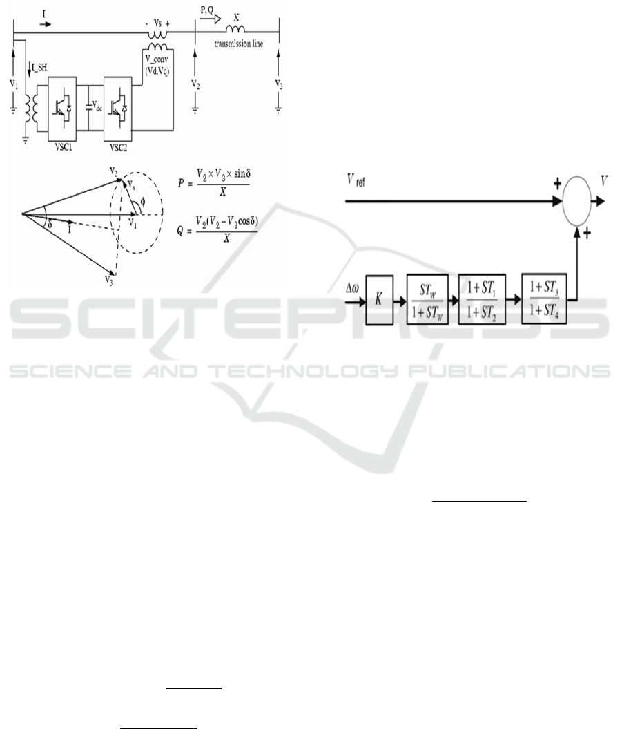
trade active and reactive power. Figure 1 shows a
schematic diagram of a unified power flow controller
and its phasor diagram.
Figure 1: Solo line diagram of UPFC and phasor diagram.
An insulated gate bipolar transistor (IGBT) is
used to connect the two voltage source converters in
UPFC back-to-back via a shared DC link. One
utilized a shunt transformer to link to the transmission
line in parallel while the other used a series
transformer to link to the transmission line in series.
By using a DC link capacitor the shunt converter
delivers the actual power that the series converter
requires. The AC voltage with a regulated magnitude
and phase angle is inoculated into the transmission
line by the series converter. The phasor diagram
offers a standard way to depict the liaison between the
system voltage and current. Phasors are used to depict
the voltages V1, V2 and V3 with V2 being impacted
by the series-injected voltage Vconv. The angle is
essential for figuring out the power flow since it
shows the phase difference between V2 and V3.
Using the following formulas real power P and
reactive power Q can be articulated.
P
∗∗
--------(1)
Q
- ----------(2)
Where the transmission line reactance is denoted
as X. By altering the amplitude and phase angle of the
injected voltage Vconv, these equations show how
the UPFC controls the power flow.
3 POWER SYSTEM STABILIZER
A Power System Stabilizer (PSS) is an additional
excitation controller that mitigates system
irregularities by giving generators a damping torque
component. Maintaining the system transient stability
and controlling power generating system instability
are made easier with the use of a power system
stabilizer controller.
Figure 2: Block diagram of PSS Controller.
Gain block, signal washout block (Tw), a high
pass filter and phase compensator of Lead-Lag block
comprise the Power System Stabilizer controller
block diagram seen in Figure 2. Equation (3) is the
transfer function T(s) of the Power System Stabilizer
controller, where K
pss
is the PSS gain.
𝑇𝑠
----------(3)
4 SIMULATION AND
METHODOLOGY
One of the most popular FACTS devices is the UPFC.
In this work, the solo-line diagram of the modelled
power system is displayed in Figure 3, which
represents a test system model. FACTS devices are
used to standardise the power flow and improve the
transmission capacity of the power system.
This system uses a UPFC to standardize the power
flow. The system is comprised of two 500KV/230KV
Enhancement of Transient Stability Performance Using UPFC with PSS in Large Power Network
637
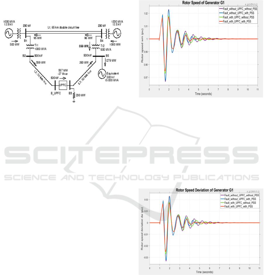
transformer banks (Tr1 and Tr2) and five node (B1 to
B5) coupled in a loop arrangement via transmission
lines (L1, L2, L3). The 1500 MW generated by two
power plants on the 230 KV system is sent to a 200
MW load connected at node B3 and a 500 KV, 15,000
MVA equivalent.
Figure 3: Test System Models.
The 500 KV node B3 active and reactive power as
well as the voltage at node B are managed by the
UPFC which is situated at the right end of line L2.
One shunt converter and one series converter both
100 MVA IGBT-based are coupled via a DC bus to
form the UPFC. In successions with line L2 the series
converter can inoculate up to 10% of the minimal
line-to-ground voltage (28.87 KV).
The test system is a transmission system without
the UPFC device that has a problem. Transmission
line L1 between the system buses B1 and B4 is where
the fault is formed. Near bus B1, a three-phase-to-
ground failure happens. There is symmetry in the
three-phase-to-ground (LLLG) fault. In a test system
model transmission system power flow is controlled
by the UPFC under fault conditions. At the 500kV
node B3 the UPFC device which is sited at the right
end of L2 regulates the voltage at node B_UPFC and
the active and reactive power at node B3. The system
transmission line L1 which connects buses B1 and B4
is where the LLLG fault is formed.
5 SIMULATION AND RESULTS
In the MATLAB domain, a test system model
transmission system was used to simulate both with
UPFC and without UPFC related faults. A three-
phase to ground fault is induced for 0.4 seconds next
to bus B1 in order to analyze the system performance.
A number of measures including rotor speed, rotor
speed deviation, terminal voltage, active power and
reactive power are used to test the power system
enhancement. Compared to PI-based controllers the
UPFC with PSS is far more effective at dampening
out system oscillations.
Figure 4: Rotor speed of generator G1.
Fig.4 illustrates how the rotor speed of generator
G1 is examined following the fault resolution. The
rotor speed oscillates for a longer period of time
without UPFC and PSS controller than when these
devices are used. Under unusual circumstances the
UPFC with PSS controller performs far better than
the PI controller. UPFC with PSS improves transient
stability by reducing the first peak magnitude and
setting time considerably according to the results.
Figure 5: Rotor speed deviation of generator G1.
Fig.5 displays the generator G1 rotor speed
deviation both with and without PSS and UPFC.
Compared to a PI controller, a UPFC with PSS
controller reduces rotor speed deviation oscillations,
INCOFT 2025 - International Conference on Futuristic Technology
638
first peak and settling time once the problem is fixed.
Rotor angle stability has improved.
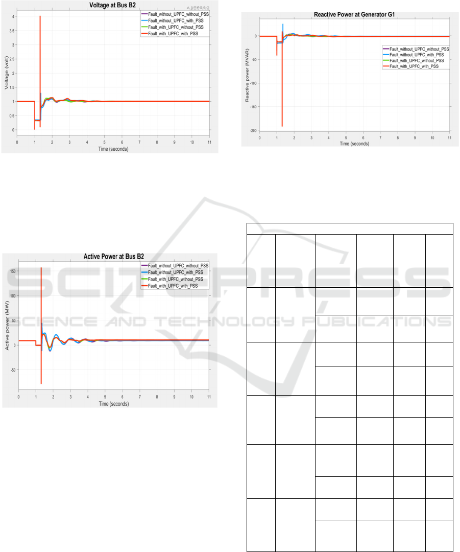
Figure 6: Voltage at bus B2.
Fig. 6 shows bus B2 terminal voltage both with
and without UPFC and PSS conditions. According to
the results UPFC with PSS stabilizes the system and
works well following a post-fault condition.
Figure 7: Active power at bus B2.
Fig.7 talks about real power at bus B2 during a 0.4
s fault period both with and without UPFC and PSS.
After the fault has been unfurnished the active power
with UPFC with PSS increases demonstrating the
power control capacity of UPFC with PSS which
further improves transmission line system
performance by reducing oscillation and managing
power flow.
Fig. 8 shows the reactive power at node B2 with
and without PSS and UPFC over a 0.4 second fault
period. The rise in reactive power with UPFC and
PSS following fault defrayal shows that reactive
power is supported by maintaining the UPFC and PSS
voltage profile to improve power system
performance.
Figure 8: Reactive power at node B2.
Table 1: System response during LLLG fault without PSS.
Without Power S
y
stem Stabilize
r
Sr.
No.
Parame
ters
Control
ler
First
Peak
Setti
ng
Time
(sec)
No.
of
Osc
illat
ion
1
Rotor
speed
of
generat
or G1
Without
UPFC
1.019 9.4 8
With
UPFC
1.017 8.8 6
2
Rotor
speed
deviati
on of
G1
Without
UPFC
0.019 9.2 8
With
UPFC
0.017 8.5 6
3
Voltag
e at
node
B2
Without
UPFC
1.29 6.5 4
With
UPFC
4.0 5.5 2
4
Active
power
at node
B2
Without
UPFC
44 8.1
8
With
UPFC
159 5.5 4
5
Reactiv
e
power
at node
B2
Without
UPFC
25 6.5 4
With
UPFC
10 5.2 2
Table 1 above shows that the system cannot react
as fast to changes in power system oscillation and
Enhancement of Transient Stability Performance Using UPFC with PSS in Large Power Network
639

voltage without a Power System Stabilizer (PSS) as it
can with one. Instability will result from the
oscillation increasing.
Table 2: System response during LLLG fault with PSS.
With Power S
y
stem Stabilize
r
Sr.
No.
Paramet
ers
Controll
er
First
Peak
Setti
ng
Time
(sec)
No.
of
Osc
illat
ion
1
Rotor
speed of
generato
r G1
Without
UPFC
1.019 6.1 5
With
UPFC
1.017 5.5 4
2
Rotor
speed
deviatio
n of G1
Without
UPFC
0.019 6.1 5
With
UPFC
0.017 5.5 4
3
Voltage
at node
B2
Without
UPFC
1.29 6 4
With
UPFC
4.0 4.9 2
4
Active
power at
node B2
Without
UPFC
44 5.6
6
With
UPFC
159 4.5 4
5
Reactive
power at
node B2
Without
UPFC
25 5.5 4
With
UPFC
10 4.8 2
A system with Power System Stabilizers will
provide better transient stability and dynamic stability
of the large power network. Table 2 above shows that
the number of oscillations the value of the first peak
and the settling time for the various strictures such as
rotor speed and rotor speed deviation of G1, voltage,
real and reactive power at node B2 of the transmission
system are all lower when UPFC is used than when it
is not.
6 CONCLUSIONS
According to the simulation results, the UPFC is
essential for improving the power system
performance when there is a problem. The outcomes
unequivocally demonstrate how well the UPFC
system is able to stabilize voltage, rotor speed and
rotor speed deviation during the abrupt significant
disturbance as well as maintain active and reactive
power via the line. Comparing the suggested system
with UPFC to the traditional system with a PI
controller the former is noticeably better. The
combination of UPFC and PSS also improves the
transient stability of the power system with PSS
playing a major role. The transient enactment of the
power system is greatly enhanced by the combination
of the UPFC and PSS.
REFERENCES
V. K. Chandrakar and A. G. Kothari, (2006) “Comparison
of RBFN based STATCOM, SSSC and UPFC
Controllers for Transient Stability improvement”, in
2006 IEEE PES Power Systems Conference and
Exposition, Atlanta, GA, USA, Nov., pp 1-5,
https://doi.org/10.1109/PSCE.2006.296415.
Nidhi Singh1, Rahul Kumar Jha2, Hari Dutta Pandey3,
Jitendra Dahal4, (2023) “Design and Simulation of
Unified Power Flow Controller for Improving
Transient Stability” in International Conference on
Technologies for Computer, Electrical, Electronics &
Communication (ICT-CEEL).
P. Jagtap and Vinod K. Chandrakar, (2021) “Comparative
study of UPFC controllers to improve transient and
dynamic stability of power system”, in IEEE 4th
International Conference on Computing, Power and
Communication Technologies (GUCON), Malaysia,
September 2021, pp 1-7,
https://doi.org/10.1109/GUCON50781.2021.9573804.
Kantilal Joshi and Vinod Chandrakar, (2016) “Transient
Stability Improvement using UPFC-SMES in a Multi
Machine Power System”, in International Journal of
Applied Power Engineering (IJAPE), 5(1):14-21, DOI:
10.11591/ijape.v5.i1.pp14-21.
Hayder Khaleel, (2024) “Unified Power Flow Controller
(UPFC) used to relieve power congestion on a
500/230KV grid”, in Journal Europeen des Systemes
Automatises, Vol. 57, No. 3, pp. 699-708.
V. K. Chandrakar and A. G. Kothari, (2008) “ ANN-based
Static Synchronous Compensator for Improving
Transient Stability performance”, in (203)
International Journal of Power and Energy Systems, pp
1-5, DOI:10.2316/Journal.203.2008.2.203-3871.
Raghad Hameed and Nourl Admed Said, (2023)
“Improvement of the Power System’s Transient
Stability using the Unified Power Flow Controller with
Fuzzy Logic Technique”, in Journal of Techniques
5(3):pp 61_72 DOI: 10.51173/it.v5i3.1249.
P. Jagtap and Vinod K. Chandrakar, (2023) “Advanced
UPFC Controller to Improve Transient and Dynamic
Stability of Power System”, in International
Conference on Advances in Mechanical Engineering,
2763(2024)012003, DOI: 10.1088/1742-
6596/2763/1/012003.
P. Jagtap and Vinod K. Chandrakar, (2024) “Intelligent
method for power flow using Artificial Neural Network
with UPFC”, in International Conference on Advances
INCOFT 2025 - International Conference on Futuristic Technology
640

in Mechanical Engineering 2023, 2763-012004, 2024,
DOI: 10.1088/1742-6596/2763/1/012004.
Kantilal Joshi and Vinod Chandrakar, (2017) “Power
oscillation damping using ultracapacitor and voltage
source based FACTS controllers”, in IEEE
International Conference on Electrical,
Instrumentation and Communication Engineering
(ICEICE),pp 1-6.
V. K. Chandrakar and A. G. Kothari, (2007) “RBFN based
Static Synchronous Series Compensator (SSSC) for
Transient Stability improvement”, Control,
Automation, Robotics and Vision, 2006. ICARCV’ 06.
9
th
International Conference on, DOI:10.1109
/ICARCV.2006.345227.
V. More and V. Chandrakar, (2016) “Performance of power
system improvement by using FACTS device: Interline
Power Flow Controller”, in international journal of
Power Systems, Vol. 1.
S. N. Dhurvey and V. K. Chandrakar, (2008) “Optimized
POD in coordination with UPFC for damping of power
system oscillations”, in 43rd International Universities
Power Engineering Conference, Padua, Italy, DOI:
10.1109/UPEC.4651450.
Sapana Bhande and Vinod K. Chandrakar, (2022) “Static
synchronous series compensator (SSSC) to improve
power system security”, in International Conference on
electronics and renewable system (ICEARS), pp 266-
270.
Vedashree Rajderkar and Vinod Chandrakar, (2023)
“Security Enhancement through the Allocation of a
Unified Power Flow Controller (UPFC) in a Power
Network for Congestion Management”, Engineering,
Technology & Applied Science Research 13 (4), pp
11490-11496.
Sapana Bhande and Vinod K. Chandrakar, (2022) “Fuzzy
logic based static synchronous series compensator
(SSSC) to enhance power system security”, in IEEE
IAS Global Conference on Emerging Technologies
(GlobConET),pp 667-672.
Sapana Bhande and Vinod K. Chandrakar, (2023)
“Enhancement of power system security by the
intelligent control of a static synchronous series
compensator”, in Engineering, Technology & Applied
Science Research 13 (1), pp 11953-11958.
R. H. Adware and Vinod K. Chandrakar, (2022)
“Comprehensive Analysis of STATCOM with SVC for
Power Quality Improvement in Multi Machine Power
System”, in 2nd IEEE International Conference on
Power Electronics & IoT Applications in Renewable
Energy and its Control (PARC), pp1-5.
Prajakta Vaidya and VK Chandrakar, (2022) “Exploring the
enhanced performance of a static synchronous
compensator with a super-capacitor in power
networks”, in Engineering, Technology & Applied
Science Research 12 (6), pp 9703-9708.
R.H. Adware, P. P. Jagtap and J. B. Helonde, (2010) “Power
system Oscillations damping using UPFC damping
controller”, in 3rd International Conference on
Emerging Trends in Engineering and technology, pp
340-344.
Prajakta Vaidya and VK Chandrakar, (2022) “Congestion
management of large power network with static
synchronous compensator”, in 2nd International
Conference on Intelligent Technologies (CONIT), pp 1-
5.
Prajakta Vaidya and V.K. Chandrakar, (2022) “Congestion
management of large power network with static
synchronous compensator”, in 2nd International
Conference on Intelligent Technologies (CONIT), pp 1-
5.
V. P. Rajderkar and Vinod K. Chandrakar, (2022)
“Enhancement of Power System Security by Fuzzy
based Unified Power Flow Controller”, in 2nd
International Conference on Intelligent Technologies
Hubli,India,pp1-5 https://doi.org/10.1109/CONIT
55038.2022.9847699.
R.H. Adware and Vinod K. Chandrakar, (2022) “Power
quality enhancement sthrough reactive power
compensation using hybrid STATCOM”, in 2nd
International Conference on Power, Control and
Computing Technologies (ICPC2T), 1-5.
Vedashree p. Rajderkar and Vinod K. Chandrakar, (2023)
“Design coordination of a fuzzy based unified power
flow controller with hybrid energy storage for enriching
power system dynamics”, in Engineering, Technology
& Applied Science Research 13 (1), pp 10027-10032.
Enhancement of Transient Stability Performance Using UPFC with PSS in Large Power Network
641
