
Performance Analysis of 3D-Printed X-Band Horn Antenna Coated with
Different Conductive Materials
D. Nagaraju
1
a
, Kodari Rakesh Yadav
1 b
and Devajji Haneesh Reddy
2 c
1
Department of Electronics and Communication Engineering, Sanskrithi School of Engineering, Puttaparthi, Sri Sathya Sai
District, India
2
Department of Electronics and Communication Engineering, Nitte Meenakshi Institute of Technology, Bengaluru, India
Keywords:
3D Printing, X-Band Horn Antenna, Additive Manufacturing, Conductive Coating, Copper Plating, Gain,
Reflection Coefficient, VSWR.
Abstract:
This study evaluates the performance of 3D-printed X-band horn antennas, focusing on designs fabricated with
additive manufacturing (AM) methods and coated with various conductive materials. Conductive coatings like
silver paint, copper tape, and copper plating were applied to examine their effects on antenna performance.
Key metrics assessed include gain, reflection coefficient, and voltage standing wave ratio (VSWR). Findings
indicate that the copper-plated antenna demonstrates superior performance, with the highest gain and lowest
reflection coefficient among all tested materials.
1 INTRODUCTION
Antennas are critical in communication systems, es-
pecially in satellite and wireless communication. X-
band antennas are preferred for high-frequency app li-
cations like radar, telecommunications, and weather
monitoring due to their directivity, low power loss,
and high gain(A. I. Dimitriadis, 2 017). Tra ditional
metallic fabrication methods result in heavy, costly
designs. This research explores AM techniques
as lightweight, cost-effective alternatives(M. Kilian,
2017). Conductive coatings—silver paint, copper
tape, and coppe r plating—are applied to determine
which offers the best antenn a performance( S. Ver-
ploegh, 2017).
Be advised that papers in a tec hnically unsuitable
form will be returned for retyping. After returned the
manuscrip t must be appropriately modified.
1.1 Motivation
Exploring AM e nables lightweight, customizable an-
tenna designs that are not feasible with c onventional
manufacturing. Testing different conductive coatings
may lead to an accessible, high-frequency antenna so-
a
https://orcid.org/0000-0002-6156-5596
b
https://orcid.org/0000-0002-5385-0805
c
https://orcid.org/0009-0007-8602-0257
lution, re ducing the n eed for metals and costly ma-
chining. Potential applications extend to aerospace,
telecommunications and defense industries.
1.2 Problem Statement
Tra ditional metal-based antennas are heavy and
costly, with limited scalability. This study investi-
gates wh e ther 3D-printed antennas with cond uctive
coatings can retain high gain, low reflection coeffi-
cient, and effective impedance matching, providing a
viable, lightweight alternative .
Table 1: Developing Antenna Specifications.
1 Frequency (8-12) GHz
2 Height 1.016 cm
3 Width 2.286 cm
4 Return loss (-25 to -50) dB
5 Antenna Gain (10-25) dB
6 VSWR 1
Based on the requirement a WR-90 Rectangu-
lar waveguide is selected as the operating frequency
range is in the frequency range of X band 8 to 12 GHz.
594
Nagaraju, D., Yadav, K. R. and Reddy, D. H.
Performance Analysis of 3D-Printed X-Band Horn Antenna Coated with Different Conductive Materials.
DOI: 10.5220/0013597900004664
Paper published under CC license (CC BY-NC-ND 4.0)
In Proceedings of the 3rd International Conference on Futur istic Technology (INCOFT 2025) - Volume 2, pages 594-597
ISBN: 978-989-758-763-4
Proceedings Copyright © 2025 by SCITEPRESS – Science and Technology Publications, Lda.
2 LITERATURE REVIEW
Horn antenn as have been developed since the 20th
century f or radar and satellite applications, with Roy
et al. documenting their evolution(H. Yao, 2017). Yao
et al. demonstrated the use o f copper-based coatings
on 3D-printed antenna s, achieving competitive gain
and reflection coefficients in Ka-band applications.
Chuma et al. found that copper-plated 3D-printed an-
tennas perform well at X-band frequencies, with su-
perior impedance matching over alternatives like sil-
ver paint or copper tape.
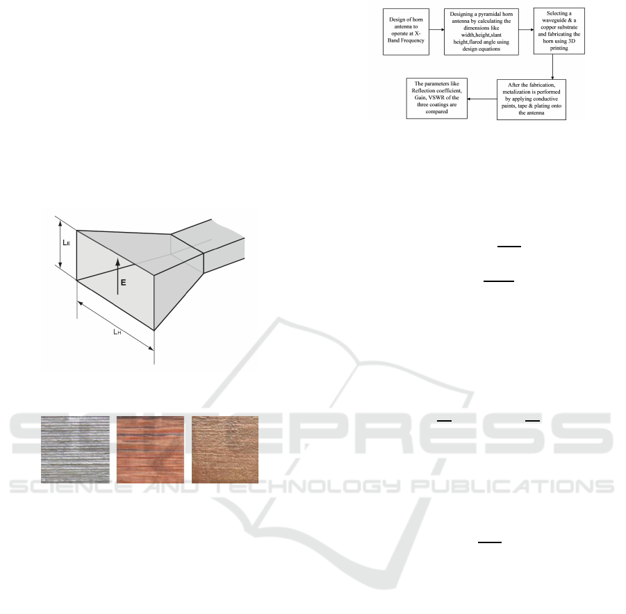
Figure 1: Pyramidal Horn Antenna
Figure 2: Different types of coatings used
3 METHODOLOGY
3.1 Design and Fabrication
Three identical horn antennas were design e d with
CAD and fabrica te d using Fused Deposition Model-
ing (FDM) with ABS plastic. Each was coated with
silver paint, cop per ta pe, or copper plating(S. Ver-
ploegh, 2017). A carbon layer was added before elec-
troplating for improved adhesion on th e copper-plated
antenna.
3.2 Designing of Pyramidal Ho rn
Antenna
The design of a pyramidal horn antenna involves pre-
cise calculations to ensure efficient signal propagatio n
and minimal reflection lo sses. The following param-
eters are critical to the design process:
Figure 3: System Design
3.2.1 Flared Dimensions
The flared angle of the horn antenna is calculated us-
ing:
Ψ
e
= tan
−1
B
1
2L
E
(1)
where:
B
1
=
p
2λL
E
and L
E
is the slant height in the E-plane.
3.2.2 Aperture Dimensions
The aperture dimensions f or the E-plane and H-plane
are given by:
a =
λ
0
2
and b =
λ
0
4
(2)
where λ
0
is the free-space wavelength.
3.2.3 Directivity
The directivity of the horn antenna is calculated as:
D =
4πA
λ
2
(3)
where A is the aperture area and λ is the operating
wavelength.
3.3 Simulation and Testing
HFSS software simulated g ain, VSWR, and r e flection
coefficient for each coating. The test was performe d
with a Vector Network Analyzer (VNA), which mea-
sures return loss, impedance matching, an d radiation
patterns. Simulated and measured results were com-
pared for accuracy.
3.4 Mapping of the Design into
Software
The designed pyramidal horn antenna was imple-
mented using HFSS (High-Frequency Structure Sim-
ulator). The mapping process involved the following
steps:
Performance Analysis of 3D-Printed X-Band Horn Antenna Coated with Different Conductive Materials
595
3.4.1 3D Model Creation
The CAD model of the antenna was created based on
the calculated parameters. The software allowed for
precise modeling of flare angles, aperture dimensio ns,
and waveguide sections.
3.4.2 Material Assignment
Material properties such as conductivity and permit-
tivity w e re assign e d to the model. For example:
σ
copper
= 5.8 × 10
7
S/m (4)
3.4.3 Boundary Conditions and Excitation
Boundary conditions were set to mimic real-world en-
vironm ents. Waveguide port excitation was applied at
the input to simulate signal propagation.
3.4.4 Simulation Setup
The frequency range was set to 8GHzto 1 2 GHz, and
performance metrics such as gain, S11, and VSWR
were analyzed.
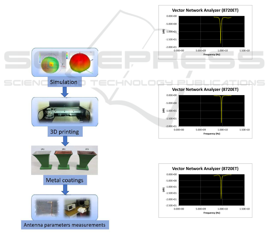
Figure 4: Antenna Fabrication Process
4 RESULTS AND DISCUSSION
4.1 Gain Comparison
The copper-plated ante nna showed the highest gain,
probably due to copper’s high conductivity and mini-
mized r e sistive losses(E. L. Chuma, 2019). Silver and
copper tape coatings showed lower gain, which could
be attributed to challenges in uniformity and conduc-
tivity(D. Nagaraju, 2021a).
The gain of the horn antenna was observed to be
highest for coppe r-plated designs:
G = 20 dB at 10 GHz (5)
4.2 Reflection Coefficient (S11)
Figure 5: Reflection coefficient of silver painted horn An-
tenna
Figure 6: Reflecti on coefficient of Copper taped horn An-
tenna
Figure 7: Reflection coefficient of Copper plated horn An-
tenna
Copper-plated antennas had the lowest reflection
coefficient (S11) values, with le ss sign a l loss c om-
INCOFT 2025 - International Conference on Futuristic Technology
596

pared to silver paint and copper tape, whose S11
values were higher due to surface roug hness(D. Na-
garaju, 2021b).
The reflection coefficient values for the different
coatings are
S11
copper
= −15 dB (6)
S11
silver
= −10 dB (7)
4.3 VSWR
VSWR results for the copper-plated antenn a indicated
near-ideal impedance matching with VSWR close to
1. Silver and copper tape coatings had slightly higher
VSWR values, reducing transmission efficiency.
The re sults obtained from simulations and practi-
cal measurements are summarized below.
The VSWR values ind ic a te efficient impedance
matching for copper plating:
VSWR
copper
= 1.2 (8)
VSWR
silver
= 1.5 (9)
4.4 Radiation Patterns
The radiation patterns were consistent with theoreti-
cal predic tions, showing high directivity in the ma in
lobe for all designs.
5 CONCLUSION
This study demonstrates the effectiveness of cop-
per plating for 3D-printed X-band antennas, sup-
porting the feasibility of AM as a lightweight, cost-
efficient alternative. Future studies can explore new
condu c tive materials, printing techniques, an d hybrid
materials to optimize antenna performance.
REFERENCES
A. I. Dimitriadis, e. a. (2017). Polymer-based additive man-
ufacturing of high-performance waveguide and an-
tenna components. In Proceedings of the IEEE. IEEE.
D. Nagaraju, N. P. G. (2021a). Design and simulation of
a compact 5.4ghz h-shaped slot antenna for rf energy
harvesting systems. In IOP Conf. Ser.: Mater. Sci.
Eng. IOP Publishing.
D. Nagaraju, N. P. G. (2021b). Design and simulation of
a multiband slot antenna for gps/wlan/wimax systems
using cst. In IOP Conf. Ser.: Mater. Sci. Eng. IOP
Publishing.
E. L. Chuma, Y. Iano, L. L. B. R. (2019). Performance
analysis of x band horn antennas using additive man-
ufacturing. In Journal of Microwaves. Journal of Mi-
crowaves.
H. Yao, S. Sharma, R. H. (2017). Ka band 3d printed horn
antennas. In IEEE. IEEE.
M. Kilian, e. a. (2017). Waveguide components for space
applications manufactured by additive manufacturing
technology. In IET Microwaves, Antennas & Propa-
gation. I ET.
S. Verploegh, e. a. (2017). Properties of 50–110-ghz waveg-
uide components fabricated by metal additive manu-
facturing. In IEEE Trans. on Microwave Theory and
Techniques. IEEE.
Performance Analysis of 3D-Printed X-Band Horn Antenna Coated with Different Conductive Materials
597
