
Design and Simulation of Smiley Patch Antenna for 5G Band
Application
Neetu Agrawal
Department of Electronics and communication Engineering, GLA University, Mathura, U.P., India
Keywords: 5G, Patch Antenna, Return Loss, Gain and Directivity.
Abstract: Fifth Generation (5G) is the most recent version, has been released at high frequencies, often known as
millimetre waves. The antenna is a crucial part of wireless communication. In this paper, a Micro- strip patch
antenna with partial ground plane structures for 5G mm–wave application is presented. The proposed antenna
design on Rogers RT5880 substrates with tangent loss 0.0009, Epsilon 2.2 and thickness 0.8mm. A compact
monopole patch antennas resonates at 26 GHz and operating band 24.4-28.2 GHz. The achieved gain 6.93
dB, return loss -25 dB and radiation efficiency 97% at resonance. The proposed antenna is simulated on CST
MWS-18 version.
1 INTRODUCTION
A device that emits or receives electromagnetic
waves is called an antenna. It acts as an interface
between a transmitter/receiver and open space,
through the conversion of electrical signals into
electromagnetic waves and vice versa facilitating
wireless communication. In wireless communication
systems such as satellite communication, GPS, cell
phones, and radar, a micro strip patch antenna is a
popular antenna type. Because of their low profile,
lightweight design, and simplicity in manufacturing
utilizing printed circuit board (PCB) technology,
these antennas are widely used (Balani, 2016),
(Kraus, John, et al. , 1973). The components of a
typical micro strip patch antenna are a patch, ground
plane, feed line, and dielectric substrate. A patch is a
radiating element that is usually composed of a
conducting substance, such as gold or copper. It is
positioned above a substrate that is dielectric
(Agrawal, 2020). The antenna's working frequency
and efficiency are influenced by the dielectric
substrate, which also offers mechanical support.
Teflon, Rogers, and FR4 are typical materials. On the
other side of the substrate lies, a conducting layer
called the Ground Plane. The feed line excites the
patch. The fringing fields around the outer edges of a
patch antenna cause it to radiate. The patch functions
as a resonant cavity that produces electromagnetic
waves when it is activated by an RF signal. The
patch's size and the substrate's characteristics are the
main factors that affect the resonant frequency. Micro
strip patch antennas play a key role in 5G wireless
networks because of their small size, low weight,
simplicity of integration with printed circuit boards
(PCBs), and appropriateness for high-frequency
operation, especially in millimetre-wave (mm Wave)
bands (24 GHz to 40 GHz and beyond). Essential
parameters of 5G are high frequency operate in sub 6
GHz and mm wave band, high gain, compact size and
wide band width (Agrawal, Neetu, et al. , 2021). This
paper covers the design and performance
characteristics of a single-band micro strip patch
antenna suited for 5G technology. The Rogers 3003
substrate was used to create the micro strip planar
antenna, which allowed for excellent efficiency and
stable characteristics in the 26 GHz 5G operating
spectrum described in the research (Slowik, Nowak,
et al. , 2024). In this study, a novel 4x8 micro strip
patch array antenna that operates in the 26 GHz range
is presented. The suggested antenna is built on a
Rogers Duroid RT5880 substrate that is 0.508 mm in
height and has a dielectric constant of 2.2. The
antenna simulation result exhibit excellent
performance with a 1.1 GHz bandwidth, a 21.26 dBi
gain, and a small dimension of 110 x 80 mm 2, all of
which are highly promising for 5G V2X
communications (Band, 2024). This article describes
the design of a rectangular micro strip patch antenna
operating in the 26 GHz band, as well as the
construction of antenna arrays based on this design.
778
Agrawal, N.
Design and Simulation of Smiley Patch Antenna for 5G Band Application.
DOI: 10.5220/0013585700004664
Paper published under CC license (CC BY-NC-ND 4.0)
In Proceedings of the 3rd International Conference on Futuristic Technology (INCOFT 2025) - Volume 1, pages 778-782
ISBN: 978-989-758-763-4
Proceedings Copyright © 2025 by SCITEPRESS – Science and Technology Publications, Lda.
Beam steering may be accomplished by introducing
an appropriate phase difference between the array
parts (Ghenjeti, Barrak, et al. , 2023). This research
presents a high-gain broadband parasitic micro strip
antenna operating at 26 GHz for 5G and Internet of
Things applications (Pal, Bandyopadhyay, et al. ,
2023). The objective of this research is to improve the
antenna's gain and other radiation properties by
combining many slot configurations into a single
rectangular patch, which is frequently found in other
5G antennas. This antenna operates on 26 and 28 GHz
band, most widely used in 5G (Şeker, Güneşer, et al.
, 2019). Many MIMO antenna for 5G-band
application using PCB technology is presented
(Agrawal, Gupta, et al. , 2003), (Agrawal, Gupta, et
al. , 2020), (Agrawal, Gupta, et al. , 2022), (Agrawal,
Gupta, et al. , 2024).
2 ANTENNA DESIGN
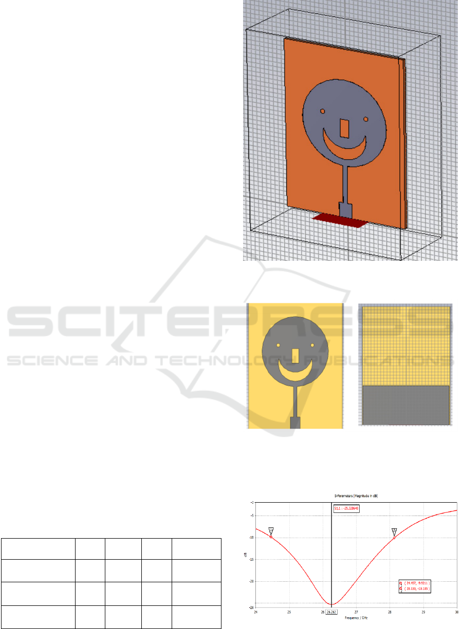
The proposed antenna perspective view is shown in
Figure 1 and geometric front view and back view is
shown in Figure 2. The physical dimensions is
depicted in Table 1. The CST tool optimized the
design parameters after they are determined using the
standard feed line and circular patch formula. The
proposed antenna is design on Rogers’s 5880
substrate with a relative permittivity of 2.2 and a loss
tangent of 0.0009. The overall circuit board size is
27*38* 0.8 mm
3
to fit inside medium and big touch
screen smart phones of today. On the top of Rogers
substrate, a circular shape patch with radius of 9.7
mm is inserted and modified micro strip feed line is
used with proper impedance matching.
The radiating patch includes two circular slot look
like eyes, one rectangular slot as nose and half-moon
shape slot as mouth, which look like as smile face.
The slotted patch antenna produces desired antenna
parameters. At the bottom of substrate, a partial
ground plane is made with perfect conductor material
instead of full ground gives good results. The ground
plane size 27mm* 12.6 mm.
Table 1: Physical dimension of antenna
Parameters w l fw1 fl1
Size (mm) 27 38 2.9 3.3
Parameters fw2 fl2 gw gl
Size (mm) 1 9.9 27 12.6
Figure 1: Perspective view
a) Front view b) Back View
Figure 2: Geometric views of proposed design
Figure 3: Return Loss (S
11
) of proposed antenna
Design and Simulation of Smiley Patch Antenna for 5G Band Application
779
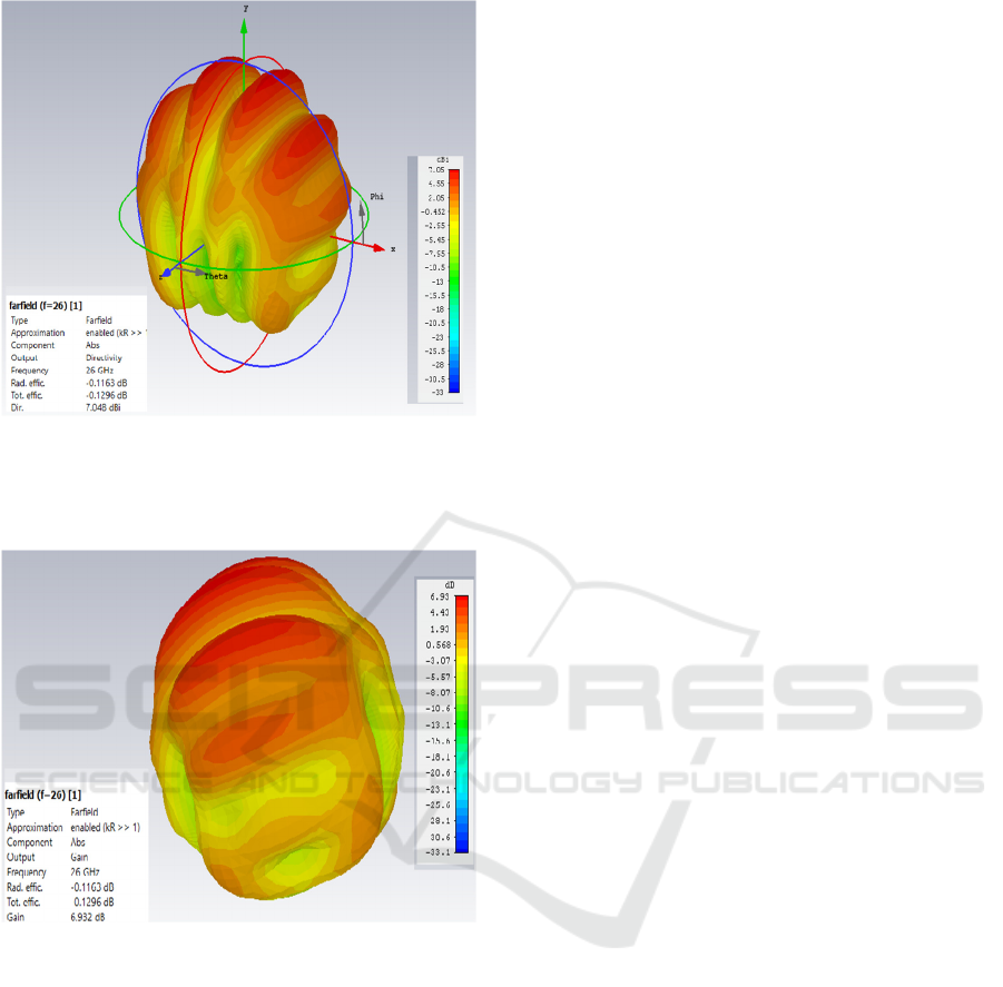
Figure 4: Directivity of proposed antenna
Figure 5: Gain of proposed antenna
3 SIMULATED RESULTS
The proposed antenna result like return loss (S
11
),
gain and directivity, are all simulated using CST
(Computer Simulation Tool). Figure 3 shows the
return loss of Smile shape micro strip Patch Aantenna
(MSPA).
The simulationn result of return loss is -25 dB at
26 GHz resonance frequency, the impedance
bandwidth is 3.8 GHZ, and operating band range is
24.4-28.2GHz. The proposed antenna has directivity
7.05dB as shown Figure 4 and maximum gain 6.98
dB as shown in Figure 5.
4 COMPARATIVE STUDY OF
PROPOSED ANTENNA
The proposed antenna is designed for 5G application.
Several antennas have been mentioned in the
literature, which resonates at 26 GHz mm wave band.
In terms of impedance bandwidth, return loss, gain
and directivity performance parameters of proposed
antenna, are compared with existing antennas
including application and its type. Table 2 shows a
comparison of 5G antenna resonates at 26 GHz based
on enhanced performance with modern literature. In
terms of impedance bandwidth, proposed antenna has
wide band almost 3.8GHz as compared to all reported
antenna except antenna design using DGS. The gain
of proposed antenna is better than antenna design
referenced (Oliveira, Goncalves, et al. , 2021),
(Taweel, et al. , 2018) and has directivity 7.05 dB is
better than referenced antenna (Oliveira, Goncalves,
et al. , 2021).The return loss is 25 dB at resonance
which is better than antenna design (Oliveira,
Goncalves, et al. , 2021). Directivity parameter are
not given most of designs like (Aziz, , et al. , 2003),
(Al-Taweel, et al. , 2018), (Ghenjeti, Barrak, et al. ,
2023). Impedance bandwidth is not given in (Saha,
Mandal, et al. , 2024) antenna designs and gain is not
mentioned in (Saha, Mandal, et al. , 2024) antenna
design. However, proposed antenna has included all-
important parameters. The proposed antenna has wide
bandwidth, suitable gain, return loss and directivity as
per standard, which is important for 5G antenna.
5 CONCLUSIONS
An optimzed modified single band high bandwidth
micros tip patch antenna that is appropriate for 5G
wireless communication is presented in this study.
This study introduces a circular patch antenna that
resembles an emoji and uses several slots with a
modified feed line. High gain, increased directivity,
and improved return loss make the smiley antenna
ideal for 5G networks.
INCOFT 2025 - International Conference on Futuristic Technology
780
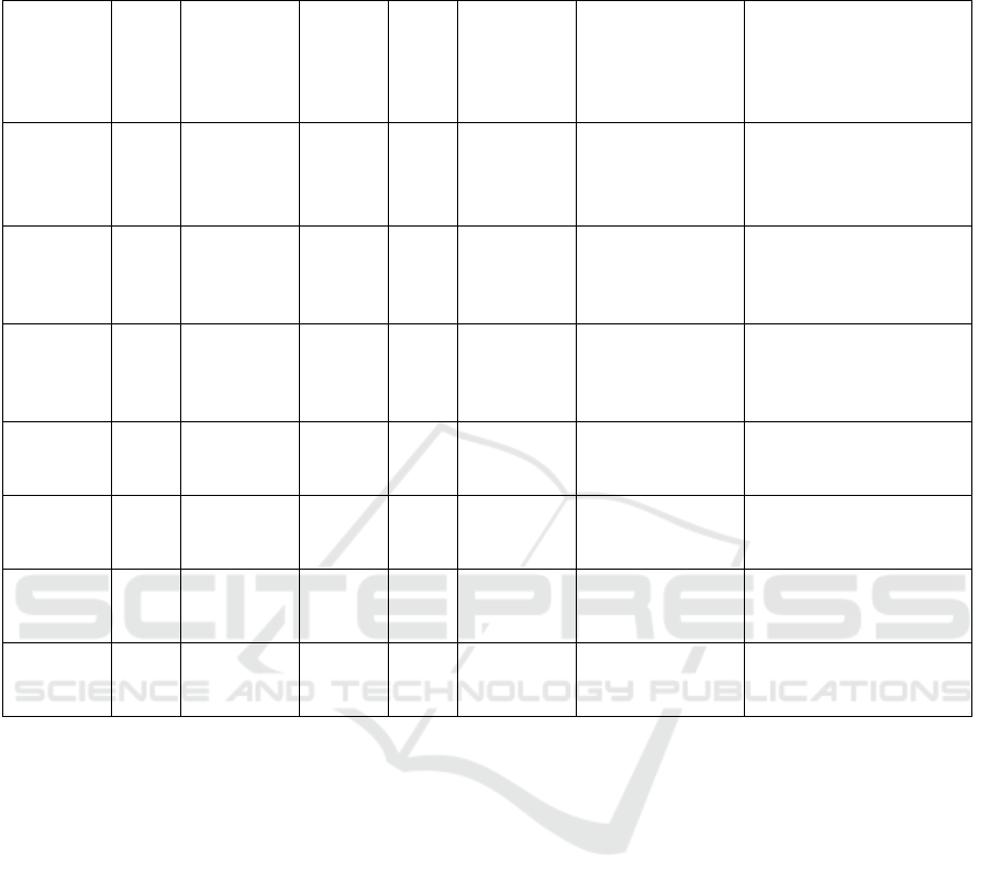
Table 2: Comparison of proposed antenna with existing antenna
REFERENCES
Balani CA. Antenna Theory: Analysis and Design. 4th ed.
New Jersey: John Wiley and Sons Wiley & Sons; 2016
Kraus, John D., and Keith R. Carver.. Electromagnetics
[by] John D. Kraus [and] Keith R. Carver. New York:
McGraw-Hill 1973.
Agrawal N. Enhanced Performance of Microstrip Antenna
with Meta-material: A Review. Advances in
Communication, Devices and Networking:
Proceedings of ICCDN 2020. 2022:221-31.
Agrawal, Neetu, Manish Gupta, and Sanjay Chauhan.
"Design and Simulation of MIMO antenna for low
frequency 5G band application." 2021 2nd Global
Conference for Advancement in Technology (GCAT).
IEEE, 2021
A. Slowik, K. Nowak and M. Czyzewski, "Microstrip
planar antenna for 5G 26 GHz
band," 2024 25th International Microwave and Radar
Conference (MIKON), Wroclaw, Poland, 2024, pp.
369-372, doi: 10.23919/MIKON60251.2024.10633951
S. Ghenjeti, R. Barrak and S. Hamouda, "High Gain and
Compact Microstrip Patch Antenna Array Design for
26 GHz Broadband Wireless Systems," 2023 IEEE
Symposium on Computers and Communications
(ISCC), Gammarth, Tunisia,
2023, pp. 932-937, doi:
10.1109/ISCC58397.2023.10218290
S. Ghenjeti, R. Barrak and S. Hamouda, "High Gain and
Compact Microstrip Patch Antenna Array Design for
26 GHz Broadband Wireless Systems," 2023 IEEE
Symposium on Computers and Communications
(ISCC), Gammarth, Tunisia, 2023, pp. 932-937, doi:
10.1109/ISCC58397.2023.1021829
Pal and A. K. Bandyopadhyay , "Design Studies of 26 GHz
Antenna Array for 5G Applications," 2023 3rd
International Conference on Range on Range
Technology (ICORT), Chandipur, Balasore, India
Ref. Freq
uenc
y
(GH
Z)
Impedance
Bandwidth
Return
Loss
(dB)
Gain Directivity Antenna Type Application
(Ghenjeti,
Barrak, et
al. , 2023)
26 1.26 26.08 7.9 --
Rectangular
microstrip
antenna
5G V2X
communications.
(Oliveira,
Goncalves
, et al. ,
2021)
26 2.49 -21.44 4.18 3.44 Quarter circular
slot rectangular
patch antenna
Quarter circular slot
26.0
25.9
3.591
3.888
-20.53
-44.51
(with
DGS)
5.37
5.88
7.13
(with DGS)
Half-moon shape
antenna
5G or high frequency
band application
(Saha,
Mandal, et
al. , 2024)
26.6 - -17 - 7.9 Antenna using
MEMS
5G or high frequency
band application
(Aziz, et
al. , 2003)
26 3.54 -33.4 10 -- Rectangular patch high quality online
education and 5G
application
(Al-
Taweel, et
al. , 2018)
26 - 25.6 5.74 -, Wang shaped
antenna
wireless communication,
mobile robotics
application,
proposed 26 3.8 25 6.93 7.05 Slotted smile
circular patch
antenna
high-quality online
education and other 5G
applications
Design and Simulation of Smiley Patch Antenna for 5G Band Application
781

2023, pp. 1-4, doi:
10.1109/ICORT56052.2023.10249191
T E. S. Oliveira, J. F. Goncalves, J. R. Reis, M. Vala and R.
F. S. Caldeirinha, "High-Gain Wideband Parasitic
Microstrip Antenna for 5G and IoT at 26 GHz," 2021
Telecoms Conference (ConfTELE), Leiria, Portugal,
2021, pp. 1-5, doi
10.1109/ConfTELE50222.2021.9435457
C. Şeker and M. T. Güneşer, "Design and simulation of 26
GHz patch antenna for 5G mobile handset," 2019 11th
International Conference on Electrical and Electronics
Engineering (ELECO), Bursa, Turkey, 2019, pp. 676-
678, doi: 10.23919/ELECO47770.2019.8990634
A Super High Gain L-Slotted Microstrip Patch Antenna for
5G Mobile Systems Operating at 26 and 28 GHz
Saha, D., Mandal, S. and Purkait, K., 2024. Design of a
Half-Moon-Shaped Microstrip Patch Antenna With
Defected Ground Structure (DGS) for 5G Applications
at 26 GHz. Cureus, 16(11
M Abdel-Aziz et al., "Design, implementation and
measurement of 26.6 GHz patch antenna using MEMS
technology," IEEE Antennas and Propagation Society
International Symposium. Digest. Held in conjunction
with: USNC/CNC/URSI North American Radio Sci.
Meeting (Cat. No.03CH37450), Columbus, OH, 2003,
pp. 399-402 vol.1, doi: 10.1109/APS.2003.1217481
Agrawal N, Gupta M, Chouhan S.” Quad port meander line
MIMO antenna with the stepped ground structure for
5G wireless application”. 2022 IEEE 6th Conference on
Information and Communication Technology (CICT-
2022)(Scopus Index Conference
Agrawal N, Gupta M. Isolation Enhancement Techniques
for UWB-MIMO System: A Review. In2020
International Conference on Power Electronics & IoT
Applications in Renewable Energy and its Control
(PARC) 2020 Feb 28 (pp. 113-117). IEEE.
Agrawal N, Gupta M, Chouhan S (2022). Modified ground
and slotted MIMO antenna for 5 G sub- 6 GHz
frequency bands" is submitted to the International
Journal of Microwave and Wireless Technologies,
Cambridge
Agrawal N, Gupta M, Chouhan S,(2024) Multiport Shared
Radiator for Signal Transmission of 5G Millimeter
Wave Application is published to SSRG International
Journal of Electronics and Communication Engineering
Malik Hasan Al-Taweel1 et al “Mili-Meter Wave Wang
Shaped Patch Antenna For 5G De-sign Antenna At 26
Ghz” 2018 Opcion 34(85):2289-2301
INCOFT 2025 - International Conference on Futuristic Technology
782
