
Comparison of Experimental Shaft Power of a Centrifugal Pump:
Wireless Strain Gauges, Load Cell Sensor, and Electrical Approaches
Philippe St-Louis, Bassem El Assaf, Guyh Dituba Ngoma and Fouad Erchiqui
School of Engineering, University of Quebec in Abitibi-T
´
emiscamingue,
445, Boulevard de l’Universit
´
e, Rouyn-Noranda, J9X 5E4, Canada
Keywords:
Centrifugal Pump, Shaft Power, Efficiency, Stress, Strain, Wireless Strain Gauges, Load Cell Sensor.
Abstract:
This study involves an experimental investigation of a centrifugal pump driven by an electric motor to deter-
mine the pump shaft power using three different approaches for power quality control. The centrifugal pump
is operated at a constant rotational speed while varying the flow rate. To evaluate the relevance and accuracy
of the shaft power calculation, experimental tests are conducted using an existing centrifugal pump test bench.
First, the pump shaft power is measured based on the electric power supplied to the pump motor. This shaft
power depends on the efficiency of the electric motor, which can introduce uncertainty in the performance
results when motors with different efficiencies are used. Second, wireless strain gauges are applied to the
pump shaft to measure its strains, which are converted into torque, ultimately providing the measurement of
power at the pump inlet. Third, a load cell sensor is used. The results indicate that wireless strain gauges can
accurately measure the shaft torque and allow for the measurement of shaft power with a very small relative
error compared to the shaft power obtained from electric power and motor efficiency.
1 INTRODUCTION
Centrifugal pumps are extensively used, particularly
in the industrial sector. They are designed, manu-
factured, and experimentally characterized to gener-
ate characteristic curves for head, shaft power, effi-
ciency, and cavitation, represented by the Net Posi-
tive Suction Head (NPSH) based on flow rate (G
¨
ulich,
2010). Accurately determining the mechanical power
of a centrifugal pump directly coupled to the shaft of
an electric motor is crucial for ensuring energy effi-
ciency, performance, durability, reliability, and safety,
thereby enabling efficient, economical, and sustain-
able pump operation. Mechanical power varies with
the pump flow rate. In most cases, the mechanical
power of a pump is determined using the input electric
power and the efficiency of a fixed or variable speed
electric motor. Given that the efficiency of the electric
motor can vary from one motor to another, it would be
beneficial to know the power directly at the pump’s
input to more accurately determine its performance.
This is especially important when pump manufactur-
ers deliver pumps separately to be connected to the
user’s electric motor, which is not tested on the test
bench for pump characterization.
Several research studies have evaluated the me-
chanical power of a pump based on the electric power
input to the electric motor (Hydraulic Institute, 2011).
In (Pambudi et al., 2024; Ahonen et al., 2012), the me-
chanical power of a centrifugal pump is calculated us-
ing the electric power of a three-phase alternating cur-
rent motor, taking into account the motor’s efficiency.
(Pambudi et al., 2024) describes the parameters that
significantly affect the electric motor’s efficiency, as
well as its electrical and mechanical losses. (Ahonen
et al., 2012) illustrates the pump characteristics as a
function of the electric current.
Moreover, (Sezer and S¸ahin, 2023) presents an ex-
perimental investigation of centrifugal pump charac-
teristics, where the electric power is calculated using
the measured electric current and voltage. The overall
efficiency of the pump is determined using the pump
head and electric power. However, the mechanical
power is not calculated, and the variation of electric
power with flow rate is illustrated.
Additionally, the mechanical power of a pump can
be determined using load cell technology, which cal-
culates torque from the force and lever arm. The shaft
power is then obtained by multiplying the torque by
the angular speed of the electric motor, with its rota-
tional speed measured using a speed sensor. Wireless
strain gauges are also employed to calculate the me-
St-Louis, P., El Assaf, B., Ngoma, G. D., Erchiqui and F.
Comparison of Experimental Shaft Power of a Centrifugal Pump: Wireless Strain Gauges, Load Cell Sensor, and Electrical Approaches.
DOI: 10.5220/0013557800003970
In Proceedings of the 15th International Conference on Simulation and Modeling Methodologies, Technologies and Applications (SIMULTECH 2025), pages 305-311
ISBN: 978-989-758-759-7; ISSN: 2184-2841
Copyright © 2025 by Paper published under CC license (CC BY-NC-ND 4.0)
305

chanical power of a pump. Specifically, shear stress is
derived from the shear strain of the pump shaft, which
is obtained from the normal strains indicated by the
strain gauges. The torque is then calculated from the
shear stress and the shear modulus of the shaft mate-
rial, considering the shaft geometry.
In (Gujarati et al., 2020), a multi-axis force torque
sensor is developed, incorporating a strain measuring
sensor, a signal processing circuit, and a data pro-
cessing solution. The study compares force sensing
solutions using strain gauges, piezoelectric sensors,
and force-sensitive resistors. In (Malonda and Di-
tuba Ngoma, 2023), a test bench is created to deter-
mine the strains and stresses on a pump shaft with
an impeller using wireless strain gauge technology.
Additionally, (Iriarte et al., 2021) estimates mechan-
ical loads in shafts using strain gauges, identifying
the optimal gauge locations on the shaft. In (Billur
and Kerem, 2024), strain gauges are used to experi-
mentally measure strain values of steel material dur-
ing tensile, bending, and torsion tests within the ma-
terial’s linear region. Numerical analysis using the
finite element method and theoretical approaches are
also employed to compare strain value results. (Sabah
Al-Dahiree et al., 2022) details the design and anal-
ysis of a strain gauge load cell, covering everything
from initial conceptual design to shape optimiza-
tion and calibration. This approach ensures ample
load capacity using low-cost materials while achiev-
ing highly accurate force measurements. The load
cell’s structured shape is optimized through stress-
strain analysis using the finite element method, en-
hancing its characteristics by reducing weight and in-
creasing sensitivity within the allowable load range.
Furthermore, (Bleho et al., 2023) conducts an exper-
imental study to measure the force load on a single
blade as the pump rotates, using a strain gauge and a
data acquisition system.
From the foregoing, the error made when reading
the torque on the pump shaft from the motor electric
current is not precisely known. Therefore, to ensure
better quality control in centrifugal pump systems,
this research aims to compare different approaches for
determining mechanical power on the pump shaft and
to validate the relevance of measuring the torque at
the pump.
2 CENTRIFUGAL PUMP
PARAMETERS, ELECTRICAL
VOLTAGE AND STRAIN FROM
THE TRAIN GAUGE
2.1 Centrifugal Pump Parameters
2.1.1 Pump Shaft Power from Electric Motor
Current
The electric power input to the electric motor can be
expressed as (Ahonen et al., 2012):
P
e
=
√
3 E I P
f
(1)
where: E is the electrical voltage in a branch; I is
the electric current in a branch; and P
f
is the power
factor of the electric motor (cosφ).
When the measured shaft power on a centrifugal
pump test bench is derived from the current entering
the electric motor, it can be written as:
P
s
= P
e
η
e
(2)
where η
e
is the electric motor efficiency.
Furthermore, the shear stress on the pump shaft is
given by:
τ = G γ (3)
where G is the shear modulus, it is expressed as
G =
E
2(1+ν)
; E is the Young’s modulus; ν is the
Poisson’s ratio and γ is the shear strain.
The shaft torque is given by:
T =
Jτ
r
(4)
where r is the pump shaft radius and J is the the
polar moment of inertia of the shaft (J =
πr
4
2
).
Additionally, the mechanical power can be formu-
lated as:
P
s
= T ω (5)
where ω is the angular velocity of the electric mo-
tor.
2.1.2 Pump Head
The pump head can be written as follows:
H =
p
in
−p
out
ρ g
(6)
SIMULTECH 2025 - 15th International Conference on Simulation and Modeling Methodologies, Technologies and Applications
306
where p
in
is the pump pressure inlet; p
out
is the
pump pressure outlet; ρ is the liquid density; and g is
the gravitational acceleration (9,81 m/s
2
).
2.1.3 Pump Hydraulic Power
The hydraulic power provided by a pump can be ex-
pressed by:
P
h
= ρ g Q H (7)
where Q is the flow rate.
2.1.4 Pump Efficiency
The overall efficiency of a pump is the ratio of the
hydraulic power to the shaft power:
η =
P
h
P
s
(8)
2.2 Relationship Between Electrical
Voltage and Strain from the Strain
Gauge
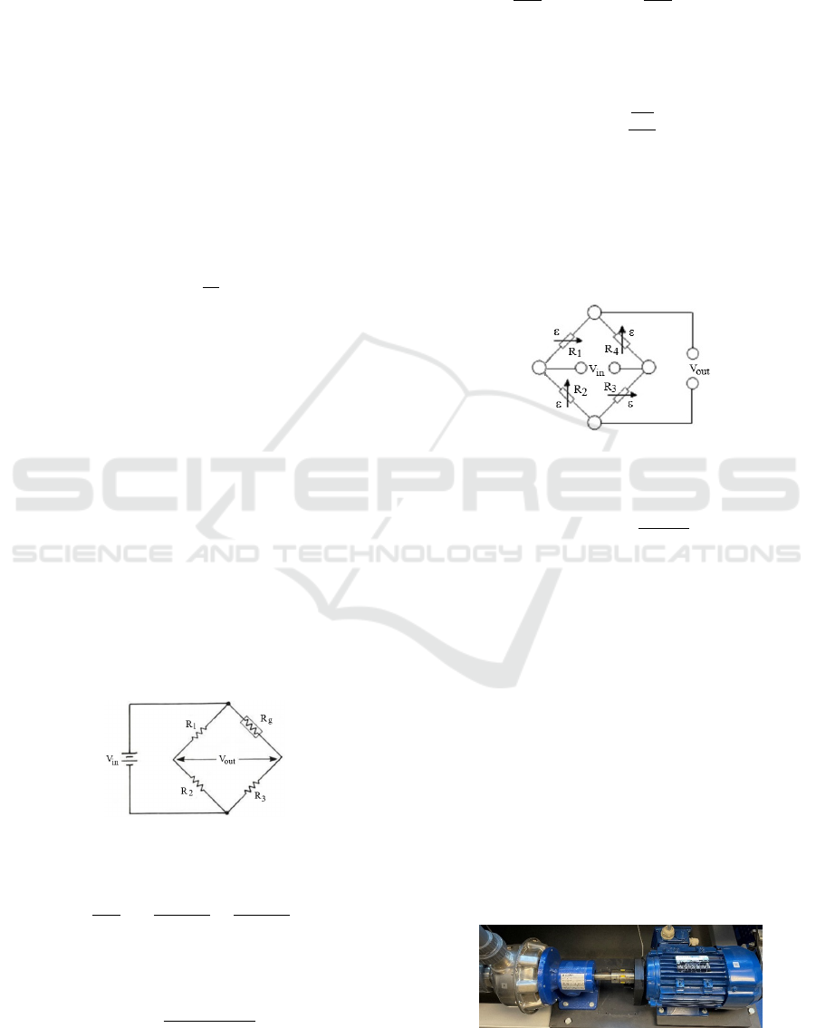
Strain gauge technology utilizes a Wheatstone bridge
circuit to accurately measure small changes in resis-
tance caused by strain. The simple Wheatstone bridge
circuit (Hewlett-Packard Co., 1981) can be character-
ized by an arrangement of four resistances on two par-
allel branches, as indicated in Figure 1. There are two
resistances (R
1
and R
2
) in series in the first branch
and two other resistances (R
g
and R
3
) in series in the
second branch. The circuit is powered with a given
voltage V
in
. The strain gauge is represented by the re-
sistance R
g
, and when the material deforms, its resis-
tance changes, resulting in a different voltage reading
between the resistances of the two branches, V
out
.
Figure 1: Simple Wheatstone Bridge Circuit.
The ratio of V
out
to V
in
is expressed by:
V
out
V
in
= (
R
3
R
3
+ R
g
−
R
2
R
1
+ R
2
) (9)
For an unbalanced Wheatstone bridge circuit, the
measured strain is formulated as follows:
ε =
−4V
r
GF(1 + 2V
r
)
(10)
where
V
r
=
V
out
V
in
!
strained
−
V
out
V
in
!
unstrained
, (11)
GF is the gauge factor based on the gauge mate-
rial. It is given by:
GF =
∆R
g
R
g
ε
, (12)
∆R
g
is the change in resistance of the gauge when
strained (∆R
g
= R
g,strained
−R
g
).
Furthermore, for a full Wheatstone bridge circuit
as depicted in Figure 2 (Hottinger Br
¨
uel and Kjær,
2025), the strain can be determined using Equation
13.
Figure 2: Wheatstone Bridge Circuit for Gauges Measuring
Torsion.
ε = ε
d
=
V
out
GF V
in
(13)
where ε
d
is the shear strain measured by each
gauge.
3 EXPERIMENTAL TESTS
Figure 3 shows the existing centrifugal pump test
bench (School of Engineering, 2025) used for charac-
terizing the pump under variable operating conditions
in terms of flow rates at a fixed rotational speed of the
electric motor. The tests conducted in this study allow
for a comparison between the mechanical power from
the electric current and an estimate electric motor ef-
ficiency, and the mechanical power from the torque
(load cell sensor and wireless strain gauges) and the
rotational speed. This is to determine the accuracy of
the torque measurement technology.
Figure 3: Centrifugal Pump Test Bench.
Comparison of Experimental Shaft Power of a Centrifugal Pump: Wireless Strain Gauges, Load Cell Sensor, and Electrical Approaches
307
In addition, the characteristics of the electric mo-
tor driving the test bench pump are summarized in Ta-
ble 1.
Table 1: Electric Motor Characteristics.
Voltage V ∆230/Y 400 ∆265/Y 460
Frequency Hz 50 60
Power kW 2.2 2.64
Power Factor - 0.85 0.85
Rotational speed rpm 2890 3465
Current 7.81/4.49 8.13/4.69
Efficiency 83.2 83.2
The used test bench provides a torque measure-
ment by means of the load cell sensor ”Flintec ZLB-
20kg-C3” (Flintec, 2025), making it possible to di-
rectly validate the torque from strain gauges. The
flow rate of the centrifugal pump is regulated by a
throttle valve when the centrifugal pump operates at
a fixed rotational speed. The mechanical power is
calculated from Equation (5). Moreover, the wireless
strain gauges are installed on the pump shaft to obtain
a torque value and verify that the result is consistent
using the test bench’s speed sensor to complete the
mechanical power measurement. Hydraulic power
can also be determined from the pump’s flow rate and
discharge pressure accounting for the suction pressure
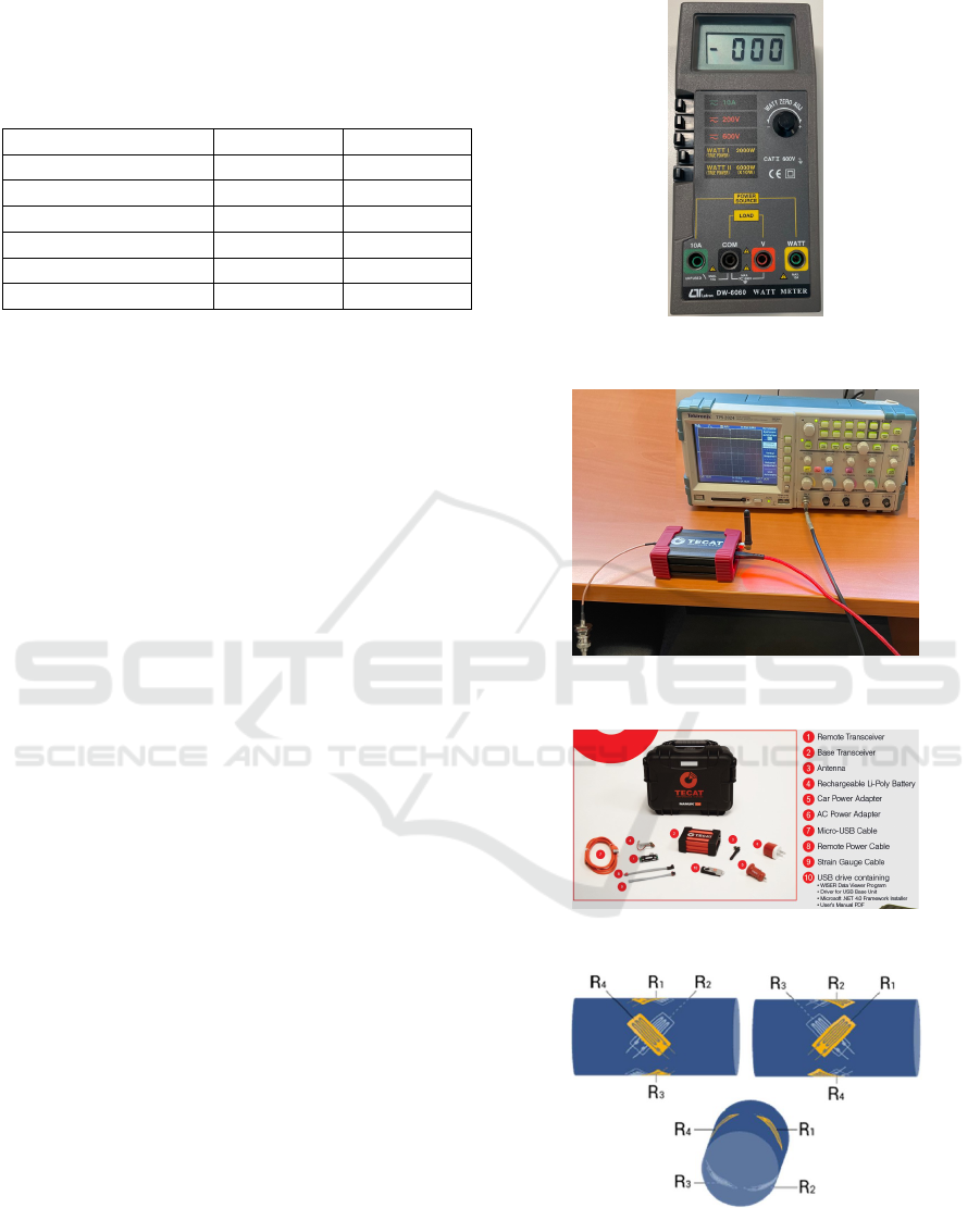
using Equation (7). To measure the electric power in-
put to the electric motor driven the centrifugal pump,
the two-wattmeter method (Matlakala et al., 2019) is
used on the three-phase circuit supplying the electric
motor. Thus, two identical wattmeters are used as in-
dicated in Figure 4 to get the electric power for each
flow rate at a fixed rotational speed.
Moreover, the voltage data from the wireless
strain gauges are transmitted by a transmitter con-
nected to the gauges and received by a receiver, which
is connected to an oscilloscope (TPS 2024 oscillo-
scope Tektronix: Figure 5) to read the measurement.
The transmitter system used is the TECAT WISER
4000 as depicted in Figures 5 and 6 (Malonda and Di-
tuba Ngoma, 2023).
Furthermore, to install the strain gauges on the
pump shaft, each gauge is attached at a 45
◦
on the
shaft as shown in Figures 7 and 8. They are connected
to the transmitter’s electronic board. Then, the elec-
tronic board and the transmitter’s battery are secured
to the shaft using adhesive tape. They are well-fixed
since they are needed to withstand a shaft rotation of
2900 rpm. The receiver part of the transmitter is con-
nected to the oscilloscope to read the voltage differ-
ences caused by the gauge strain.
To measure the strain on the gauges placed on the
shaft from the voltage read by the data acquisition
Figure 4: Lutron DW-6060 Watt Meter (School of Engi-
neering, 2025).
Figure 5: Connecting the Receiver and Oscilloscope for
Laboratory Testing (School of Engineering, 2025).
Figure 6: TECAT WISER 4000 (TECAT Performance Sys-
tems, LLC, 2018).
Figure 7: Arrangement of Strain Gauges on the Shaft (Hot-
tinger Br
¨
uel and Kjær, 2025).
system, the Wheatstone bridge theory is used for the
specific gauge arrangement in this test (Figure 2). The
shear strain is calculated using a gauge factor of 2.06.
SIMULTECH 2025 - 15th International Conference on Simulation and Modeling Methodologies, Technologies and Applications
308
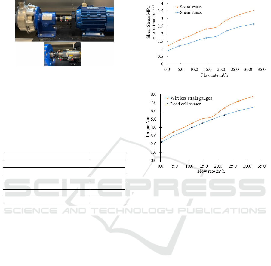
Figure 8: Strain Gauges on the Pump Shaft (School of En-
gineering, 2025).
4 RESULTS AND DISCUSSION
Experimental tests for centrifugal pump head, strain,
stress, torque, mechanical power, and electric power
are conducted using the reference data provided in Ta-
ble 2.
Table 2: Reference data for the pump.
Shaft diameter [m] 0,0246
Young’s modulus [Pa] 196x10
9
Shear modulus [Pa] 75.3x10
9
Rotational speed [rpm] 2900
Water density at 25
◦
[kg/m
3
] 997
Water kinematic viscosity [m
2
/s] 0.884x10
−6
Flow rate range [m³/h] 0.5 −31.9
4.1 Torques from Load Cell Sensor and
Wireless Strain Gauges
Figure 9 shows the curves of shear strain and shear
stress on the pump shaft as functions of the flow rate.
The shear strains from the wireless strain gauges are
determined using Equation 13, and the correspond-
ing shear stresses on the pump shaft are calculated
using Equation 3. From this figure, it can be seen that
both shear strain and shear stress on the pump shaft
increase with the rise in the flow rate of the centrifu-
gal pump. This can be explained by the increase in
shaft torque with rising flow rate.
The strain gauges and transmitter can then be po-
sitioned on the shaft to measure strains and calculate
the transmitted torque. This, combined with the mea-
surement from an accurate load cell sensor, allows for
the verification of the measurement tool’s accuracy.
Moreover, the torque curves from the load cell and
wireless strain gauges are illustrated in Figure 10. The
torque obtained with the load cell sensor is greater
than that measured by the strain gauges.
Focusing on the torque values, significant discrep-
Figure 9: Shear Strain and Shear Stress versus Flow Rate.
Figure 10: Shaft Torque versus Flow Rate.
ancies between the measurements provided by the
wireless strain gauges and those provided by the load
cell sensor are noted. The load cell sensor reads
only very small strains, which can lead to some un-
certainty in the measurement since very small varia-
tions in strain can have a large effect on the final mea-
surement. Furthermore, the strain gauges may not be
placed exactly at 45° as intended, since it is difficult
to accurately measure the angle and precisely adhere
them to such a small shaft, which undoubtedly affects
the accuracy of their shear strain measurement.
4.2 Shaft Powers from Load Cell
Sensor, Wireless Strain Gauge
Sensor, and Electric Current
Figure 11 illustrates the mechanical powers on the
pump shaft, calculated using wireless strain gauges,
a load cell sensor, and electric current, as well as the
electric power and hydraulic power of the centrifugal
pump, all as functions of the flow rate at a rotational
speed of 2900 rpm. The mechanical power from the
electric current is determined using the motor effi-
ciency and the input electric power. From this fig-
ure, considering the mechanical power from the load
cell as a reference, it is observed that the mechani-
cal power from the wireless strain gauges is almost
Comparison of Experimental Shaft Power of a Centrifugal Pump: Wireless Strain Gauges, Load Cell Sensor, and Electrical Approaches
309
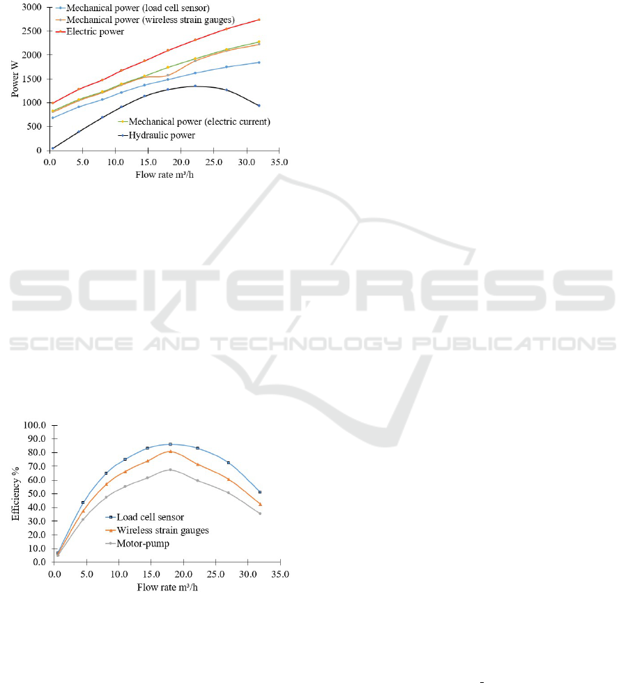
equal to the mechanical power from the electric cur-
rent. Moreover, there is a discrepancy between the
mechanical power from the strain gauges and the me-
chanical power from the load cell. This can be ex-
plained by the uncertainty in the load cell sensor mea-
surement or an error in the wattmeter measurement,
which are connected to the input of the speed con-
troller, potentially causing some power losses.
Figure 11: Power versus Flow Rate.
4.3 Efficiencies of the Motor-Pump and
Pump
Figure 12 shows the efficiency curves for the motor-
pump assembly, the pump with wireless strain gauges,
and the pump with the load cell. The figure indicates
that the efficiency of the pump measured with the load
cell is higher than that measured with the wireless
strain gauges. The motor-pump assembly has the low-
est efficiency due to losses in both the electric motor
and the centrifugal pump.
Figure 12: Efficiency versus Flow Rate.
5 CONCLUSIONS
In this study, the aim was to validate a torque mea-
surement technology to obtain a more accurate rep-
resentation of the mechanical power on the centrifu-
gal pump shaft, thereby improving the quality con-
trol process. An existing centrifugal pump test bench
was used to experimentally determine the mechanical
power on the pump shaft using three approaches: a
load cell, wireless strain gauges, and electric current.
The mechanical power was measured by operating the
centrifugal pump under different flow rate conditions
while maintaining a constant rotational speed. The re-
sults indicate that the mechanical power determined
from the wireless strain gauges closely matches the
mechanical power calculated from the electric power,
considering the efficiency of the electric motor. The
mechanical power calculated using the load cell ap-
proach was the lowest. Future work will involve using
wireless strain gauge technology to determine pump
shaft power on a larger scale in the context of tech-
nology transfer.
ACKNOWLEDGEMENTS
The authors are grateful to Technosub Inc., Indus-
trial Pumps Manufacturing and Distribution (Rouyn-
Noranda, Quebec, Canada) and the Turbomachinery
Laboratory of the Engineering School (University of
Quebec in Abitibi-T
´
emiscamingue).
REFERENCES
Ahonen, T., Kortelainen, J. T., Tamminen, J. K., and Ahola,
J. (2012). Centrifugal pump operation monitoring
with motor phase current measurement. Electrical
Power and Energy Systems, 42(1):188–195.
Billur, K. and Kerem, A. (2024). Experimental investigation
of centrifugal pump characteristics. Sigma Journal of
Engineering and Natural Sciences, 42(3):755–766.
Bleho, D., Ol
ˇ
siak, R., and Kn
´
ı
ˇ
zat, B. (2023). Experimental
system for measuring the force load of a single blade
pump. In 22nd Conference on Power System Engi-
neering. MATEC Web of Conferences.
Flintec (2025). ZLB-20kg-C3. www.flintec.com/weight-
sensors/load-cells/planar/zlb.
Gujarati, Y., Thamma, R., and Laber, J. (2020). Technolo-
gies for force/torque sensor. International Journal
of Innovative Science, Engineering and Technology,
7(12).
G
¨
ulich, J. F. (2010). Centrifugal Pumps, Second Edition.
Springer-Verlag Berlin Heidelberg, Heidelberg, Ger-
many.
Hewlett-Packard Co. (1981). Practical strain gage measure-
ments, application note 290-1. https://www.hpmemo
ryproject.org/an/pdf/an\ 290-1.pd.
Hottinger Br
¨
uel and Kjær (2025). The wheatstone bridge
circuit explained. www.hbm.com/fr/7163/wheatstone
-bridge-circuit/.
SIMULTECH 2025 - 15th International Conference on Simulation and Modeling Methodologies, Technologies and Applications
310

Hydraulic Institute (2011). American National Standard
for Rotodynamic Pumps for Hydraulic Performance
Acceptance Tests. Hydraulic Institute, New Jersey,
United States of America.
Iriarte, X., Aginaga, J., Gainza, G., Ros, J., and Bacaicoa, J.
(2021). Optimal strain-gauge placement for mechan-
ical load estimation in circular cross-section shafts.
Measurement, 174.
Malonda, P. and Dituba Ngoma, G. (2023). Numerical
investigation of a high-capacity vertical submersible
two-stage pump and realization of an experimental
test bench for determining the strains and the stresses
on a pump shaft. In 13th International Conference on
Simulation and Modeling Methodologies, Technolo-
gies and Applications. SCITEPRESS.
Matlakala, M. E., Kallon, D. V. V., Simelane, S. P., and
Mashinini, P. M. (2019). Impact of design parameters
on the performance of centrifugal pumps. In Procedia
Manufacturing. Elsevier B.V.
Pambudi, K., Tarigan, A. D., and Hamdani (2024). Anal-
ysis efficiency of 3 phase ac motor use a centrifugal
pump drive on the water tower of pdam tirtanadi, north
sumatra. Jurnal Scientia, 13(2).
Sabah Al-Dahiree, O., Osman Tokhi, M., Hassan Hadi,
N., Rasheid Hmoad, N., Ariffin Raja Ghazilla, R.,
Jen Yap, H., and Abdullah Albaadani, E. (2022). In-
vestigation of using strain gauge in tension, torsion
and bending experiments. Sensors, 22(19).
School of Engineering (2025). Turbomachinery labo-
ratory (E-216), University of Quebec in Abitibi-
T
´
emiscamingue (UQAT). www.uqat.ca.
Sezer, I. and S¸ahin, Y. S. (2023). Design and Shape Opti-
mization of Strain Gauge Load Cell for Axial Force
Measurement for Test Benches. Nigerian Journal of
Technology, 7(4):408–414.
TECAT Performance Systems, LLC (2018). WISER Model
4000 Wireless Data Sensor. https://tecatperformance
.com/wp-content/uploads/2018/10/WISER4000-10.
22.18-1.pdf.
Comparison of Experimental Shaft Power of a Centrifugal Pump: Wireless Strain Gauges, Load Cell Sensor, and Electrical Approaches
311
