
CAD Method Supporting Mechanical Innovative Design Based on
Artificial Intelligence
Gao Honghui
Yantai Vocational College, Yantai, Shandong, 264670, China
Keywords: Artificial Intelligence, Mechanical Innovative Design, CAD Method, Agent Technology.
Abstract: With the development of CAD technology, modern CAD design software is not only used to replace manual
drawing, but also plays a more and more important role in enterprises. The current focus of CAD is to adapt
to the market demand. The purpose of this paper is to study the CAD method of mechanical innovative design
based on artificial intelligence. The traditional design method based on finite element is limited by the huge
gap between CAD and CAE and the huge time-consuming caused by multiple numerical calculations, so it is
difficult for engineers to modify the CAD model and carry out CAE structural analysis quickly and accurately.
Combining the innovative research of CAD design with computer, a new CAD design method based on
artificial intelligence is developed, which provides a high-performance system for researchers by using the
high storage capacity of computer. In this paper, firstly, the mechanical innovative design method is
summarized, and then through the study of the relevant design theory of transmission parts, the object-oriented
design method is adopted. Aiming at the shortcomings of CAD system, the multi-agent is deeply studied
Based on the application of CAD technology, evolutionary technology and collaborative design technology
in CAD system, a CAD system supporting innovative conceptual design is established and implemented.
Finally, through the system test and result analysis, the static test error is 0, and the two errors of the dynamic
test line are fixed. Finally, the system runs well, and the genetic algorithm has good adaptability to the layout
design.
1 INTRODUCTION
In order to enhance their competitiveness, shorten the
product development cycle and reduce the
development cost of products, enterprises constantly
explore and practice some advanced integrated
manufacturing technology and methods of electronic
computer to adapt to the increasingly fierce market
competition (Oliveira, Rbd , et al, 2019). At the same
time, after the merger and reform of global companies
or enterprises, manufacturing industry has developed
into a global industry of large-scale, wide-ranging
and wide-ranging cooperation (Kuna and Skaan,
2019). Many famous manufacturing companies and
enterprises from the world have not only R & D
and manufacturing departments, but also relevant
parts manufacturing enterprises. Therefore, many
complex products need to be co designed and
constructed by producers and designers distributed in
different locations and locations in design (Tao and
Li, et al. 2018). All enterprises are actively using
CAD, computer - aided design ).
This paper mainly relies on the academic
background of the provincial mechanical engineering
discipline, and studies the graduate innovation
research project (cx2016b079) and the national key
basic research technology development plan ("973"
plan), The research is carried out under the guidance
and support of 2010cb328005, the key project of
national natural science fund construction
(61232014), and the general project of NSFC
construction (11472101). In order to overcome the
huge gap between CAD and CAE in mechanical
structure design and the huge effort needed in the
process of repeated calculation and modification of
structure, the geometric model of structural CAD is
realized by engineers, which is simple, convenient,
quick and accurate (Chen, J. L and C. L. Lee, 2017).
Based on the professional background of the
mechanical engineering discipline, this paper
conducts relevant research work under the support of
the provincial graduate innovation and research
project (cx2016b079), the national key basic research
and development plan (973 Plan, 2010cb328005), the
244
Honghui, G.
CAD Method Supporting Mechanical Innovative Design Based on Artificial Intelligence.
DOI: 10.5220/0013539000004664
Paper published under CC license (CC BY-NC-ND 4.0)
In Proceedings of the 3rd International Conference on Futuristic Technology (INCOFT 2025) - Volume 1, pages 244-249
ISBN: 978-989-758-763-4
Proceedings Copyright © 2025 by SCITEPRESS – Science and Technology Publications, Lda.

National Natural Science Fund key project
(61232014), and the National Natural Science
Foundation general project (11472101) ( Mandal, D.
K and C. S. Syan, 2016). In order to overcome the
huge gap between CAD and CAE in mechanical
structure design and the huge time required for
repeatedly calculating and modifying the structure,
the engineer can easily and accurately represent and
modify the geometric model of structural CAD, and
obtain the dream of the results of CAE analysis of
structure quickly and even in real time, so as to
accelerate the product development and improve
social benefits (Innovative Materials, 2016).
2 CAD METHOD FOR
MECHANICAL INNOVATIVE
DESIGN
2.1 Agent Technology
Multi agent system is one of artificial intelligence,
which has the characteristics of intelligence. In this
system, each agent is an independent and intelligent
entity, which takes action or solves problems through
interaction with external environment and
coordination between agents. Multi agent system is
usually applied in dynamic, distributed and intelligent
environment (Hadhami, et al, 2020).
2.2 The IGA-IFU Method is Used for
Accurate Reanalysis of Structural
Integration
Based on IgA, the integration of CAD and CAE is
constructed, which lays the foundation for the
subsequent real-time analysis and optimization. The
engineer can eliminate the representation error by
accurately representing the geometric model of the
structure, and easily modify the CAD geometry
model of mechanical structure by changing the
control point (Dietterich T G, 2017). The CAE model
can be obtained immediately, which avoids the
complicated conversion between CAD and CAE in
traditional methods, and the errors and time
consuming (Raedt and Kersting, et al. 2016). When
the structural modification does not affect the overall
displacement of the structure, the independent
coefficient method has a very high precision; while
when the overall displacement of the structure is
greatly affected by the structural modification,
especially when the structural modification causes the
structural deformation mode to change, the accuracy
of the independent coefficient method may not be
guaranteed (Seyedmahmoudian, et al, 2016).
3 SUPPORT THE DESIGN OF
CAD METHOD SYSTEM FOR
MECHANICAL INNOVATIVE
DESIGN
3.1 Multi Agent System
3.1.1 Question Raising
Technological innovation is the spirit and soul of
CAD. The competition of new products based on
knowledge is becoming the focus of the competition
of Chinese enterprises in the complicated global
manufacturing environment in the 21st century
(Bryson, and Winfield, 2017). At present, all kinds of
manufacturing and processing equipment
manufacturing enterprises in China have entered a
period of rapid development oriented by market main
body. The economic benefits and quality of
enterprises depend on the revolutionary innovation of
technology and products to a large extent. Whether an
enterprise has the ability to research and develop a set
of innovative products that meet the needs of the
market and the consumption mentality of different
types of customers in the coming years will become
the final decision on the survival and development of
an enterprise (Price, and Flach, 2017).
3.1.2 Multi Agent System Structure
The agent in the design environment is usually called
design agent. Design agent is a kind of computer
software that helps designers to complete the design
task in some way.
A multi agent system is generally composed of the
following aspects:
1) Multiple existing agents;
2) There is a joint intention among multiple
agents, that is, multiple agents act together to achieve
common goals;
3) Common sense: that is, the common knowledge
between agents;
4) The environment on which agent depends is the
basic guarantee for agent behavior.
Multi Agent System Supporting Innovation
Concept Design
In this system, complex design is completed by
multiple agents. Each agent has its own independent
knowledge and design decision-making scheme, and
CAD Method Supporting Mechanical Innovative Design Based on Artificial Intelligence
245

can understand the design state representation, so as
to assist us human design technology experts to
achieve the design objectives to be done. The design
strategy of agent mainly depends on some basic
algorithms, such as genetic algorithm and
classification algorithm. Once a new task is arrived,
the task decomposition agent (TDA) is used to
decompose the whole design task into many
independent sub task sets, and a product design tree
is used to represent the decomposition results. TDA
knowledge base contains many product design tree
templates. TDA selects the appropriate template
according to its product category and recommends it
to designers. The designers and engineers make
preliminary decisions and send the results to the
design agent of each component. For example, if a
user needs to submit a request for housing design,
TDA will extract the information of all components
of the house and the information of all finished houses
in a corresponding knowledge base, and decompose
the functions of these products into several relatively
independent functional components, which are
transferred to different components and design agents
for design. The design agent of each component helps
designers and personnel to do their work according to
their own tasks. When all the sub tasks are completed,
all the design results are submitted to the assembly
agent. In the process of assembly, the assembly agent
needs to check the assembly limit. For components
that do not meet the requirements, the information
that must be modified is sent to the required design
agent. After the assembly agent completes the
assembly of new products, the new products are
uploaded to the customer, and the users will evaluate
the quality of the products and give the new products
a score. If the user is satisfied with the new product,
the new product will be output. Otherwise, the
components shall be replaced or changed according
to the user's requirements. After the component is
modified, it is re submitted to the assembly agent for
assembly until the user is satisfied.
3.1.3 Specific Implementation of Agents
The implementation of component design agent
adopts genetic algorithm, which uses mathematical
functions to generate two-dimensional curves and
three-dimensional entities to inspire people's
thinking, so as to realize innovative design.
3.1.4 Improvement of Genetic Algorithm
This paper first extracts the basic features, expresses
it by component tree, then cuts and combines them,
uses genetic algorithm based on natural selection and
evolution principle, simulates the learning process
naturally, adjusts the elements of product
composition structure, and makes it have a more
efficient and reasonable structure, so as to optimize or
increase the function of products and realize the
support for innovation.
3.2 Belt Drive Design Calculation
Subsystem
Design Calculation of V-Belt
1) Main failure modes and design criteria of V-
belt drive
The main failure modes of V-belt drive are
slipping, fatigue damage, wear and static breaking of
the belt; the design criterion of V-belt drive is to
ensure that the belt has sufficient fatigue strength and
life without slipping; there are two design constraints
of V-belt drive, which are as follows:
F = 1000
≤𝐹
(1−
)
(1
)
(1) is a condition that the mechanical transmission
will not slip, where f is the friction coefficient, α is
the angle of the pulley, e is the bottom of the natural
logarithm, and V is the linear velocity of the belt. The
fatigue strength conditions are shown in (2):
𝜎
=𝜎
+𝜎
+𝜎
≤
[
𝜎
]
(2
)
Where 𝜎
is the tight edge stress, 𝜎
is the
bending stress, 𝜎
is centrifugal stress.
(2) Parameters and conditions for interactive input
or selection in V-belt design
The parameters and conditions that must be input
or selected interactively in the design of V-belt pulley
mainly include: starting type, load property and
working hours per day of belt drive, power generated
by belt drive, slip friction ratio, requirements of other
conditions, such as bearing size, center distance limit,
etc, When designing the pulley structure, it is
necessary to know the types of various driving force
generators.
3.3 Chain Drive Design Calculation
Subsystem
Chain drive is a kind of transmission widely used in
mechanical transmission. It transmits motion and
force by the meshing between sprocket teeth and
chain link. The design content of chain drive design
and calculation module includes roller chain and
tooth chain. The following is the theoretical basis of
INCOFT 2025 - International Conference on Futuristic Technology
246
chain drive module design and calculation and the
realization of roller chain design and calculation.
Design and Calculation of Roller Chain
3.3.1 Main Failure Modes
The main failure of chain drive is chain failure. The
main failure modes are: chain compression failure,
chain collision fracture, chain wear, and chain
crushing due to overload.
3.3.2 Design of Chain Drive
Because the roller chain itself is a standard part, it
only needs to select the corresponding type of roller
chain according to the design, so the main content of
chain drive design is to calculate the relevant
parameters and the design of sprocket.
3.4 Design and Calculation Subsystem
of Gear Transmission
Gear is one of the most important transmission parts,
which is widely used in mechanical industry,
automobile, aircraft, shipbuilding and other
industries. In the gear design calculation module, the
design of involute spur gear, helical spur gear and
straight bevel gear is studied and designed.
3.5 Data Processing
In the design calculation module, because the system
involves many kinds of parts, there are many kinds of
coefficients and data that need to be queried in the
part design. How to query the parameters manually
and obtain them efficiently and quickly in the design
module through programming is a key problem to be
solved in the design process of this system.
Mathematical Model of Data Processing
3.5.1 Least Square Method
For some given data (𝑥
,𝑦
)i=0,1,…,n In
the selected function type, find f (x) belonging to the
selected function type_ i) , make𝑒
=𝑓
𝑥
−𝑦
The
sum of squares of I is the smallest
𝑒
=
𝑓
𝑥
−𝑦
(3)
The value of 𝑓
𝑥
minimum.
Program Processing Of Data Table
For the table that needs to query parameters in the
design process (hereinafter referred to as the number
table), the processing method is: the data with small
amount is directly programmed; the data with large
amount is written into the program in the form of
determined table name, field name and field type
according to Microsoft Office Access The structure
of the database is structured storage, and the tables
involved in each module are stored as a database file.
1) Single parameter table processing
For the data table with only one independent
variable and a small amount of data, the data can be
directly programmed into the array, and the required
data can be obtained by querying according to the
change of the variable_ The value of 𝑘
is shown in
Table 1.
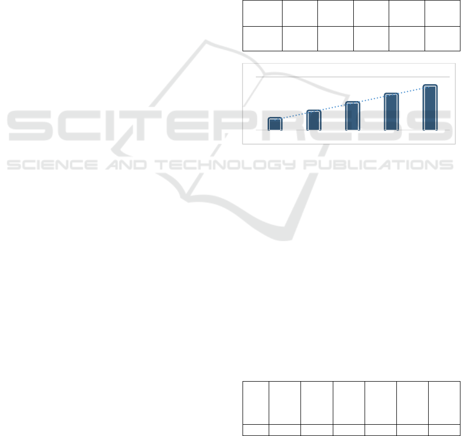
Table 1: Row number coefficient of multi row chain
Row
number
1 2 3 4 5
𝑘
1 1.7 2.5 3.3 4.1
Figure 1: Row number coefficient of multi row chain
As shown in Figure 1, the coefficient of row
number increases with the increase of row number.
When programming, define a one-dimensional array,
store the data in the table in the array, define an
integer variable I, according to the row number
change selected by the user, according to the change
of I value, you can query the array to obtain the row
number coefficient 𝑘
.
2) Interpolation query
In the design process, some tables do not list all
the data. When variables can not be directly queried
in the table to obtain the required data, interpolation
query is needed to obtain the required results. As
shown in Table 2, it is the query table of envelop
angle coefficient
Table 2: Wrap angle coefficient
Wr
ap
ang
le
180
degre
es
160
degre
es
140
degre
es
120
degre
es
100
degre
es
90
degre
es
𝑘
∝
1.00 0.95 0.89 0.82 0.74 0.69
1 1.7 2.5 3.3 4.1
1
2
3
4
5
Row
number …
Row number
CAD Method Supporting Mechanical Innovative Design Based on Artificial Intelligence
247
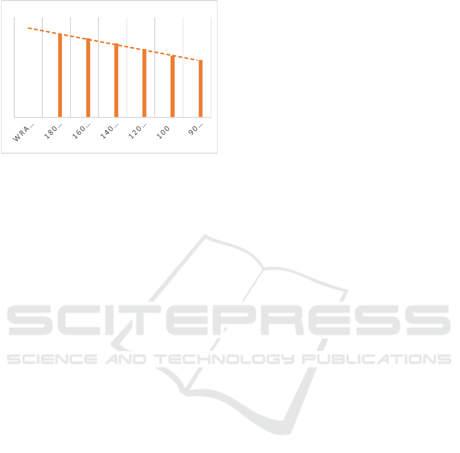
Figure 2: Wrap angle coefficient
As shown in Figure 2, the envelop angle
coefficient increases with the increase of envelop
angle, and the increase range is linear.
4 TEST AND RESULT ANALYSIS
System Test
Unit test is to test the subsystem at rest and in
motion. The main contents of static test include:
1) Consistency of variable type and scope
declaration
2) Accuracy of algorithm and formula
3) Is the logic clear
4) Is the symbol consistent
5) Is the jump accurate
6) Is data transmission accurate and consistent
7) Consistency of font style and color
8) Form style consistency
9) Can the code be simplified and the running
efficiency be improved
Through the code walkthrough and structure
review, the static test found no errors. The dynamic
test selects a typical example to test all the steps of
design and calculation, and exposes the possible
hidden errors of the system by inputting illegal
parameters in the test process, and corrects them in
time. After the completion of the subsystem test, each
subsystem is managed and controlled through a
unified interface. The display of each subsystem is
controlled through the management database, and
each subsystem controls its own display by accessing
the database. The single subsystem program cannot
run when the main interface of the system is not
running.
5 CONCLUSIONS
In this paper, an accurate numerical method based on
variable thickness is proposed. The effectiveness,
reliability and efficiency of the method are verified by
illustration, derivation and analysis, as well as by
typical examples and actual mechanical structures in
the field of automotive engineering. Although the
research of CAD system supporting innovation is still
in the research stage, the improvement and
improvement of system integrity, flexibility,
supporting innovation and collaboration brought by it
are remarkable, so its development prospect is broad.
Although some stage research results have been
achieved, there are still many new problems to be
further explored due to the constraints of time and
energy.
REFERENCES
Oliveira, Rbd , et al. "Supporting Information Innovative
design for the enhancement of lithium lanthanum
titanate electrolytes." Crystal Growth And Design
19.9(2019):4897-4901.
Kuna P , Skaan M , A Haková. Didactic materials
supporting CAD/CAE system teaching[J]. Luis Gómez
Chova, 2019:págs. 1641-1647.
Tao J , Li L , Yu S . An innovative eco-design approach
based on integration of LCA, CADCAE and
optimization tools, and its implementation
perspectives[J]. Journal of Cleaner Production, 2018,
187(JUN.20):839-851.
Chen, J. L. , and C. L. Lee . "Developing Sustainable
Innovative Products for the Bottom of the Pyramid by
Biomimetic Design Concepts." Procedia Cirp
61(2017):629-634.
Mandal, D. K. , and C. S. Syan . "[Lecture Notes in
Mechanical Engineering] CAD/CAM, Robotics and
Factories of the Future || Design and Modelling of Dual
Faceplate Centrifugal Casting Equipment for
Manufacturing of Turbine Bearing." 10.1007/978-81-
322-2740-3.Chapter 51(2016):523-534.
Integrating Innovation in Architecture (Design, Methods
and Technology for Progressive Practice and Research)
|| Innovative Materials. 2016,
10.1002/9781119164807:20-59.
Hadhami, et al. "Proposal of new eco-manufacturing
feature interaction-based methodology in CAD phase."
The International Journal of Advanced Manufacturing
Technology 106.3(2020):1057-1068.
Dietterich T G . Steps Toward Robust Artificial
Intelligence[J]. Ai Magazine, 2017, 38(3):3.
Raedt L D , Kersting K , Natarajan S , et al. Statistical
Relational Artificial Intelligence: Logic, Probability,
and Computation[J]. Synthesis Lectures on Artificial
Intelligence and Machine Learning, 2016, 10(2):1-189.
0
1
0.95
0.89
0.82
0.74
0.69
WRAP ANGLE
COEFFICIENT
WRAP ANGLE
INCOFT 2025 - International Conference on Futuristic Technology
248

Seyedmahmoudian, M. , et al. "State of the art artificial
intelligence-based MPPT techniques for mitigating
partial shading effects on PV systems – A review."
Renewable & Sustainable Energy Reviews
64.oct.(2016):435-455.
Bryson, J. , and A. Winfield . "Standardizing Ethical
Design for Artificial Intelligence and Autonomous
Systems." Computer 50.5(2017):116-119.
Price, S. , and P. A. Flach . "Computational support for
academic peer review: a perspective from artificial
intelligence." Communications of the Acm
60.3(2017):70-79.
CAD Method Supporting Mechanical Innovative Design Based on Artificial Intelligence
249
