
Business Process Modeling Techniques for Data Integration Conceptual
Modeling
Ana Ribeiro
1 a
, Bruno Oliveira
2 b
and
´
Oscar Oliveira
2 c
1
University of Tr
´
as-os-Montes and Alto Douro, Portugal
2
CIICESI, School of Management and Technology, Porto Polytechnic, Portugal
Keywords:
Data Pipelines, Business Process Model and Notation, Conceptual Modeling, Analytical Systems,
Methodology.
Abstract:
Data pipelines play a crucial role in analytical systems by managing the extraction, transformation, and load-
ing of data to meet decision-making needs, however, due to the inherent complexity of data management.
Despite their importance, the development of data pipelines is frequently carried out in an ad-hoc manner,
lacking standardized practices that ensure consistency and coherence across implementations. In recent years,
the Business Process Model and Notation (BPMN) has emerged as a powerful tool for conceptual modeling in
diverse analytical and operational scenarios. BPMN offers an expressive framework capable of representing a
wide range of data processing requirements, enabling structured and transparent design. This work explores
the application of BPMN to data integration pipeline modeling, analyzing existing methodologies and propos-
ing a standardized set of guidelines to enhance its use.
1 INTRODUCTION
The need to capture and analyze data constantly
evolves as organizations expand their business ac-
tivities (Yaqoob et al., 2016). Current trends high-
light analytical and storage approaches designed to
handle large-scale, often less structured data (Inmon,
2016). However, having access to vast amounts of
data does not guarantee informed decision-making
(Janssen et al., 2017). It is crucial to ensure that data
quality standards are maintained to support decision-
making processes effectively.
Data integration, ETL, and data pipelines are in-
terconnected concepts for modern data processing.
Data integration refers to the process of combining
data from different sources to provide a unified view,
enabling organizations to analyze and make decisions
based on comprehensive datasets (Lenzerini, 2002).
ETL is a specific subset of data integration that fo-
cuses on extracting data from disparate sources, trans-
forming it into a format suitable for analysis, and then
loading it into a destination, such as a data ware-
house (Kimball and Caserta, 2004). Data pipelines,
a
https://orcid.org/0009-0000-4462-1149
b
https://orcid.org/0000-0001-9138-9143
c
https://orcid.org/0000-0003-3807-7292
on the other hand, are end-to-end workflows that au-
tomate and streamline the process of moving, trans-
forming, and storing data (Munappy et al., 2020). A
data pipeline can encompass various stages, including
ETL, but may also involve additional operations like
data validation, enrichment, and real-time processing
(Dayal et al., 2009). In essence, ETL is one of the
key processes within a data pipeline, while data in-
tegration is the broader goal that data pipelines aim
to achieve by facilitating the seamless flow of data
across systems.
Due to the complexity of data management, ETL
processes consume significant resources. As a critical
component, ETL impacts the system’s adequacy: fail-
ure to deliver high-quality data compromises the sys-
tem’s reliability (Souibgui et al., 2019; Nwokeji and
Matovu, 2021). ETL development is typically driven
by ad-hoc practices, which, unlike traditional soft-
ware development, lack a solid methodology to guide
and document the transition from conceptual repre-
sentation to physical implementation. While some
ETL tools offer support in this regard, they often rely
on proprietary methods, notations, and methodolo-
gies. These tools primarily address the physical level
of ETL, offering limited support for conceptual prim-
itives to describe systems at a higher level (Prakash
and Rangdale, 2017).
158
Ribeiro, A., Oliveira, B. and Oliveira, Ó.
Business Process Modeling Techniques for Data Integration Conceptual Modeling.
DOI: 10.5220/0013497800003929
In Proceedings of the 27th International Conference on Enterprise Information Systems (ICEIS 2025) - Volume 1, pages 158-169
ISBN: 978-989-758-749-8; ISSN: 2184-4992
Copyright © 2025 by Paper published under CC license (CC BY-NC-ND 4.0)

Business Process Modeling and Notation (BPMN)
(Aagesen and Krogstie, 2015) is a standardized mod-
eling notation that offers a set of artifacts for model-
ing business processes. It focuses on two key aspects:
managing and planning a workflow and modeling the
implementation architecture. BPMN notation is ad-
vantageous, as it allows for process design to be ex-
plored from multiple perspectives, enhancing process
expressiveness, particularly during early development
phases. However, this ambiguity can pose challenges
for interpreting processes at the execution level during
implementation.
The remainder of this paper is structured as fol-
lows: After the introduction, Section 2 reviews the
most relevant research in the field of ETL modeling.
Section 3 outlines the approach proposed in this pa-
per for ETL conceptual modeling. Section 4 presents
a case study demonstrating the application of the pro-
posed conceptual modeling approach to a real-world
scenario. Finally, Section 5 summarizes the key con-
clusions of this work and outlines directions for future
research.
2 RELATED WORK
A Business Process Model and Notation (BPMN)
is a graphical notation for modelling business pro-
cesses[16]. BPMN emerged as a successor to
flowcharts simple diagrams with boxes and ar-
rows—and the Unified Modeling Language (UML),
the first structured method for process flow represen-
tation (Oliveira et al., 2015). BPMN is designed to be
easy to use and understand by all involved in business
processes, including business analysts, programmers,
technical implementers, and managers responsible for
monitoring the processes. Its simplicity and expres-
siveness for representing flows, participants, condi-
tions, and events have made BPMN widely adopted
across domains. The latest specification, BPMN 2.0,
published in 2011, has since become the most popular
business process modelling language. It bridges the
gap between technical and non-technical users, offer-
ing a versatile and widely understood tool supported
by BPMS. The notation’s flexibility is evident in its
three levels of modelling (Silver, 2011):
• Descriptive Modeling: This level represents an
initial view of a business process, highlighting
its main activities. It focuses on simple docu-
mentation of workflows, such as mapping and de-
scribing routine processes within an organization.
High-level and occasionally non-compliant with
BPMN validation rules, descriptive modeling en-
hances communication across the organization. It
is ideal for depicting existing processes without
delving into specifics.
• Analytical Modeling: Building on the previous
level, analytical modeling incorporates rules and
outcomes for more precise and detailed represen-
tations. It fosters collaboration among stakehold-
ers, including business analysts, technical staff,
and managers. This level clarifies process ac-
tivities and objectives, enabling detailed work-
flow representations and performance analyses for
optimization. Validation against BPMN specifi-
cations and hierarchical organization are empha-
sized. Analytical modelling is commonly used in
areas such as human resources, logistics, and pro-
curement.
• Executable Modeling: This advanced level em-
phasizes precision and detail, enabling process
execution through simulations. Simulations gen-
erate performance data and validate compliance
with BPMN modelling rules. Executable mod-
elling requires detailed descriptions of process
attributes and aims to convert diagrams into
software-ready formats like XML-based specifi-
cations (e.g., XML Process Definition Language,
XPDL).
These three BPMN representation levels differ
in abstraction, information detail, complexity, utility,
and standardization. The choice of model depends on
these factors and the purpose of the process design,
ensuring alignment with project needs and goals. In
(Oliveira et al., 2021), the authors presented a BPMN-
based conceptual modeling approach for represent-
ing ETL processes across three distinct abstraction
layers. BPMN’s expressiveness, advantageous for
ETL representation, enables diverse conceptual mod-
els due to varying thought processes and representa-
tion styles among individuals. The authors proposed
an approach that organizes ETL conceptual model-
ing into separate layers, each focusing on a specific
level of detail. This structure provides the ETL devel-
opment team with tailored tools for communication
at different phases of ETL development. Each layer
builds upon the constructs described in the preceding
layer, progressively adding detail. This incremental
enrichment of system requirements contributes to a
more agile development process. The authors embod-
ied the notion of patterns when designing this top-
down approach for conceptual modelling, providing
pre-configurable components that represent common
tasks used in the ETL environment.
In the past, several other authors focused on mod-
elling ETL, proposing methodologies for ETL con-
ceptual modeling (Vassiliadis et al., 2005), (Tru-
jillo and Luj
´
an-Mora, 2003). In (Dupor and Jo-
Business Process Modeling Techniques for Data Integration Conceptual Modeling
159

vanovi, 2014) developed a method focused on pro-
viding a simple visual overview to ease the repre-
sentation of ETL processes. Biswas et al. (Biswas
et al., 2017; Biswas et al., 2019) utilized Systems
Modeling Language (SysML) to explore requirement
and activity diagrams for conceptual representation,
which could be transformed into XML Metadata In-
terchange (XMI) for programmable interpretation. In
(Raj et al., 2020) took a broader approach by mod-
eling data pipelines, including ETL/ELT transfor-
mations across various applications and data types
(e.g., continuous or batch). The authors provide an
overview of designing a conceptual model for data
pipelines, which serves as a common communication
framework among different data teams. Additionally,
this model can facilitate the automation of monitor-
ing, fault detection, mitigation, and alerting at various
stages of the data pipeline.
However, some approaches rely on specific nota-
tions, adding complexity for ETL development teams
to learn and communicate these to non-technical
stakeholders. Adapting widely used notations can
mitigate these issues. For example, Akkaoui et al.
(Akkaoui and Zimanyi, 2009) suggested that ETL
processes can be viewed as specialized business pro-
cesses, facilitating communication among technical
and non-technical staff. BPMN, as a widely adopted
business process modeling and execution standard,
has naturally extended into ETL modeling.
We believe that BPMN is a valuable tool for ETL
modeling, as ETL processes can be understood as a
specialized type of business process. Just like tradi-
tional business workflows, ETL involves a sequence
of structured activities—data extraction, transforma-
tion, and loading—each governed by rules, dependen-
cies, and business requirements. Given this parallel,
our work explores how methodologies originally de-
signed for modeling standard business processes can
be adapted to ETL, providing a structured and in-
tuitive representation of data workflows. By using
BPMN’s expressiveness and widespread adoption, we
aim to bridge the gap between business and technical
stakeholders, enhancing communication, improving
process transparency, and enabling automation. Our
approach seeks to demonstrate that BPMN can not
only facilitate conceptual modeling of ETL but also
support optimization, monitoring, and maintainabil-
ity of ETL workflows, ultimately contributing to more
efficient data integration practices.
3 MODELLING WITH LAYERS
The development of abstract models helps improve
the understanding of the process for all involved par-
ties, whether they are business owners, business ana-
lysts, or more technical users (Soffer et al., 2012). Es-
pecially during the early stages of development, con-
ceptual models play an extremely important role, as
users validate business requirements. BPMN offers a
simple yet powerful notation for process representa-
tion, which is highly suitable for ETL processes. Be-
yond its expressiveness, BPMN also provides mech-
anisms for execution. Additionally, one advantage is
that business users are already familiar with the nota-
tion, and existing business processes can be leveraged
to understand the logic of processes and data flow.
However, adopting a notation for modelling ETL pro-
cesses with BPMN is not straightforward. Conven-
tions need to be adopted to guide the modelling pro-
cess, ensuring that there are no divergent representa-
tions of the process that could lead to misinterpreta-
tions.
Three levels of representation are defined in (Sil-
ver, 2011): Descriptive Modeling, Analytical Mod-
eling, and Executable Modeling. These levels guide
the progressive and increasingly detailed representa-
tion of processes, aligning with the needs of different
project phases. Given BPMN’s suitability for ETL
processes, this study explores how this approach can
be applied in the ETL context.
The goal of this methodology is to adapt BPMN
modeling principles for ETL across different levels,
ensuring clarity, expressiveness, and consistency in
both specification and implementation. Following
the top-down BPMN modeling approach described
in (Silver, 2011), a hierarchical structure for ETL
models is proposed. Through an analysis of BPMN
process modeling methods, the applicability of these
techniques to ETL was assessed. Based on this anal-
ysis, relevant methods and rules were selected and
adapted to fit ETL-specific requirements, defining the
key elements of each modeling level. The Executable
Modeling rely on specialized execution engines rather
than direct BPMN execution. The application of com-
position principles and carefully chosen BPMN ele-
ments ensures adherence to best practices for concep-
tual ETL modeling.
3.1 Level 1 - Descriptive Modeling
At Level 1, BPMN modeling is designed to be sim-
ple, intuitive, and easy to read, using a core set of
elements that resemble traditional flowcharts. This
level focuses on high-level process documentation,
ICEIS 2025 - 27th International Conference on Enterprise Information Systems
160

avoiding technical complexity while ensuring clarity
in workflow representation. The Level 1 palette for
BPMN 2.0 includes essential components: tasks (for
individual activities), subprocesses (for grouping re-
lated tasks), gateways (for decision logic), and events
(for process initiation and completion). These ele-
ments provide a clear, structured view of ETL work-
flows, where tasks represent ETL operations, subpro-
cesses organize process phases and gateways control
flow decisions. Events define key moments affecting
the process, such as data availability or pipeline fail-
ures. Pools and lanes introduce role-based segmen-
tation, allowing the representation of data reposito-
ries, system components, or ETL phases (extraction,
transformation, loading). While message flows ex-
ist in BPMN, they are typically minimized in Level 1
models, focusing instead on sequence flows that de-
fine the core process execution order. Annotations
and artifacts further enhance the model by providing
descriptive details, supporting human readability and
process traceability.
In adapting BPMN to ETL modeling, the Level 1
approach ensures that data engineers and business an-
alysts can collaboratively design, analyze, and com-
municate ETL processes without technical barriers.
By maintaining a consistent modeling style and focus-
ing on core BPMN elements, Level 1 lays the founda-
tion for more detailed analytical and executable mod-
els, bridging the gap between conceptual design and
implementation.
Figure 1 focuses on high-level representations of
ETL workflows, using a simplified set of BPMN ele-
ments to ensure clarity and comprehensibility. These
elements provide a structured way to describe the core
steps of an ETL process while maintaining an intu-
itive, flowchart-like visual representation. The key
BPMN elements used in this layer include:
1. Flow Objects
(a) Events: Represent the start and end of the pro-
cess.
i. Start Event: Marks the beginning of an ETL
process (e.g., data extraction initiation).
ii. End Event: Indicates the completion of the
ETL process (e.g., after loading data into the
destination system).
(b) Activities: Define process steps and transfor-
mations.
i. Task: Represents a single ETL operation, such
as data cleansing, transformation, or aggrega-
tion.
ii. Subprocess: Groups multiple tasks into a sin-
gle, reusable unit to simplify complex work-
flows.
(c) Gateways: Control the flow of execution by
defining decision points.
i. Exclusive Gateway (XOR): Directs the pro-
cess flow based on conditions (e.g., different
paths for valid vs. invalid data).
ii. Parallel Gateway (AND): Splits or synchro-
nizes multiple concurrent ETL tasks.
(d) Connecting Objects
i. Sequence Flow: Defines the execution order
of tasks within the ETL pipeline.
ii. Message Flow (limited use in Level 1): Repre-
sents interactions with external entities but is
generally reserved for higher modeling levels.
iii. Associations: Link tasks to additional infor-
mation (e.g., documentation or annotations).
2. Swimlanes
(a) Pools: Represent the overall ETL system or a
high-level organizational boundary.
(b) Lanes: Subdivide pools to illustrate responsi-
bilities, such as extraction, transformation, and
loading phases.
3. Artifacts
(a) Data Objects: Represent inputs, intermediate
results, or outputs in the ETL process.
(b) Text Annotations: Provide clarifications and
additional details for process elements.
(c) Groups: Organize related tasks for better visu-
alization and structure.
The descriptive modeling level ensures that ETL
processes are represented in a structured yet accessi-
ble format. By using a limited but powerful set of
BPMN elements, Level 1 diagrams effectively com-
municate the flow of data, transformations, and de-
pendencies while maintaining simplicity. This ap-
proach enables collaboration between business users
and technical teams, fostering a shared understand-
ing of ETL workflows before progressing to more de-
tailed analytical and executable models.
3.2 Level 2 - Analytical Modelling
Level 2 builds upon the foundational elements intro-
duced in Level 1 by incorporating intermediate events
to model dynamic behaviors within processes and
boundary events to handle task-specific conditions.
While Level 1 relies on a strict sequence where each
step follows the completion of the previous one, Level
2 introduces these elements to allow processes to re-
act to specific conditions or interruptions during ex-
ecution. This capability is particularly relevant in
ETL workflows, where tasks may require compen-
satory actions to handle exceptions or prevent process
Business Process Modeling Techniques for Data Integration Conceptual Modeling
161
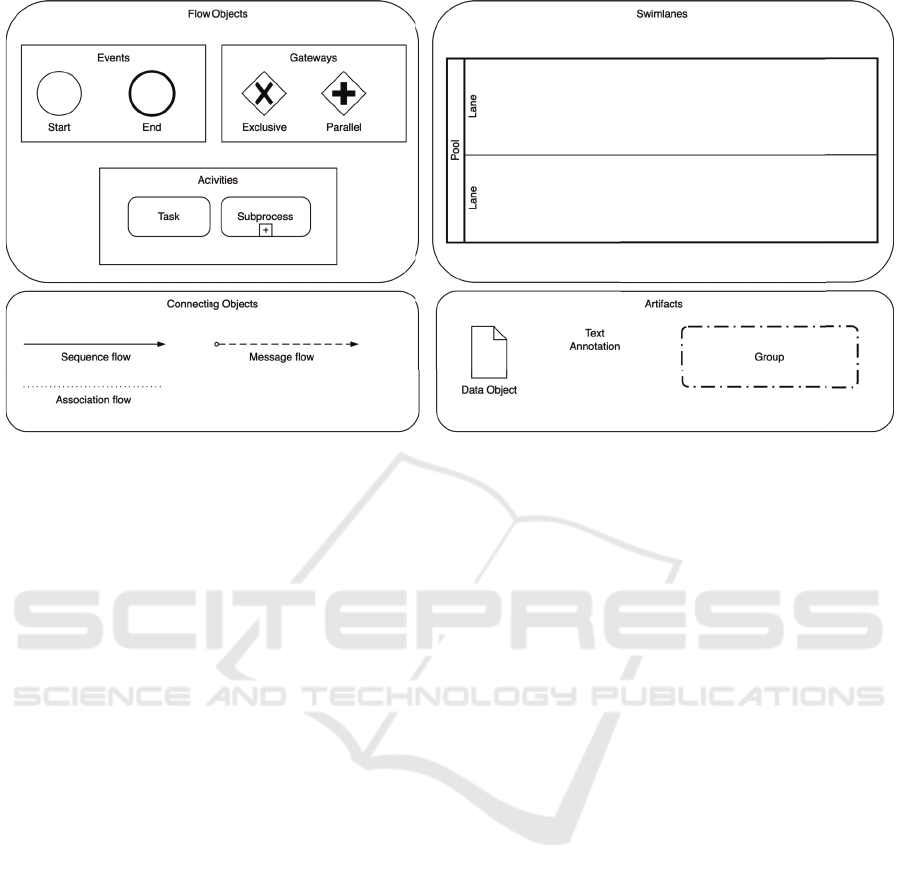
Figure 1: BPMN Elements Used in Level 1 - Descriptive Modeling.
failures. For example, in a data validation scenario,
an unexpected value encountered during a name nor-
malization task might trigger a redirection of affected
records to a quarantine table for further analysis.
Boundary events, depicted as double-lined circles
on the edge of activities, play a crucial role in en-
abling these adaptive behaviors. These events define
alternative process flows based on specific triggers,
ensuring greater fault tolerance and resilience in ETL
pipelines. Key boundary events include:
• Timer events, which introduce time-based triggers
to control execution timing.
• Message events, which handle external communi-
cations between process components.
• Error events, which manage process exceptions
by directing workflows toward predefined com-
pensatory actions.
By leveraging these elements, Level 2 BPMN
models enhance ETL process resilience, addressing
real-world challenges such as data validation errors,
timeouts, and system failures. This approach im-
proves error handling, adaptability, and process au-
tomation, ensuring robust ETL pipeline execution.
Beyond process flow control, Level 2 also formalizes
data interactions through data objects, data stores, as-
sociations, and annotations:
• Data Objects represent transient data repositories,
modeling inputs, outputs, and intermediate stor-
age.
• Data Stores represent persistent data repositories,
such as database records.
• Directed Associations link activities to these ob-
jects, specifying their role in the workflow.
• Parameterized Annotations enhance documenta-
tion by explicitly defining input/output relation-
ships and process descriptions, improving model
clarity and implementation accuracy.
For error recovery, BPMN introduces compensa-
tion activities, which serve to reverse or mitigate the
effects of a completed task. These activities are linked
to compensation events, ensuring that corrective ac-
tions restore process integrity before normal execu-
tion resumes. Notably, compensation activities do not
execute by default; they must be explicitly triggered
when a process requires rollback actions. By integrat-
ing these mechanisms, Level 2 BPMN models rein-
force error management and process transparency in
ETL workflows.
In Level 2, BPMN elements are used to create
models that support decision-making, process opti-
mization, and analysis. The main focus is on ensuring
that the models are easy to understand and reflect the
real-world process dynamics, without overcomplicat-
ing them with implementation details. Add this in the
preamble
Table 1 highlights the key differences between
BPMN elements used in Level 1 and Level 2. While
no elements are explicitly excluded in Level 2, this
level refines and extends the constructs introduced in
Level 1 by incorporating additional details and be-
havioral nuances. Level 2 introduces intermediate
events, including timer, message, and error events,
which enable processes to respond dynamically to
specific conditions. It also expands control flow capa-
ICEIS 2025 - 27th International Conference on Enterprise Information Systems
162

Table 1: Comparison of BPMN Elements in Level 1 and Level 2.
BPMN Element Used in Level 1? Used in Level 2? Notes
Events
Start Event Yes Yes Used in both levels.
End Event Yes Yes Used in both levels.
Intermediate Events Rarely Yes Used in Level 2 for dynamic behavior.
Timer Event No Yes Time-based triggers for workflows.
Message Event No Yes Handles communication between processes.
Error Event No Yes Manages process exceptions.
Activities
Task Yes Yes Used in both levels.
Sub-process Rarely Yes Expanded in Level 2 for modular design.
Ad-hoc Sub-process No Yes Allows dynamic execution of tasks.
Service Task No Yes Represents system-automated tasks.
Manual Task No Yes Represents human-performed tasks.
Gateways
Exclusive Gateway (XOR) Yes Yes Used for decision-making.
Parallel Gateway (AND) Yes Yes Used for parallel execution.
Inclusive Gateway (OR) No Yes Allows multiple paths based on conditions.
Complex Gateway No Yes Used for advanced decision logic.
Event-based Gateway No Yes Decisions based on events.
Data Objects and Flows
Data Object No Yes Represents transient data.
Data Store No Yes Represents persistent data.
Data Input/Output No Yes Models data exchanges.
Sequence and Message Flows
Sequence Flow Yes Yes Used in both levels.
Message Flow Rarely Yes More common in Level 2 for inter-process communication.
Conditional Flow No Yes Represents flows based on conditions.
Default Flow No Yes Indicates the default path in decisions.
Swimlanes
Pool Yes Yes Represents process participants.
Lane Rarely Yes More detailed role distinction in Level 2.
Artifacts
Text Annotation Rarely Yes Used more in Level 2 for documentation.
Group No Yes Helps group related activities.
bilities with complex and inclusive gateways, enhanc-
ing decision-making flexibility. Furthermore, Level 2
formalizes data interactions through data objects and
flows, while also supporting more advanced process
structuring with ad-hoc sub-processes. Artifacts such
as grouping and text annotations improve documen-
tation and process clarity. Unlike Level 1, which pri-
marily focuses on a high-level, descriptive represen-
tation of workflows, Level 2 enhances complexity by
emphasizing process analysis, conditions, data depen-
dencies, and event-driven execution, making it more
suitable for analytical modeling and execution-ready
process definitions.
3.3 Level 3 - Executable Modeling
Level 3 builds upon the descriptive and analytical
foundations established in the previous levels, extend-
ing BPMN representations to facilitate the transition
from conceptual models to deployable ETL work-
flows. Unlike Levels 1 and 2, which focus on high-
level abstraction and dynamic behavior modeling,
Level 3 introduces execution-related elements nec-
essary for the operationalization of ETL processes.
However, rather than directly executing BPMN mod-
els, this level assumes integration with specialized ex-
ecution engines, such as ETL platforms and workflow
automation tools, which interpret and implement the
defined logic in a structured, repeatable manner.
Executable modeling at this level emphasizes
the precise specification of process elements to en-
sure consistency in implementation. Key compo-
nents include service tasks, script tasks, and busi-
ness rule tasks, which serve as placeholders for data
transformation operations, validations, and orchestra-
tions. These tasks are augmented with technical de-
tails, such as parameterized configurations, metadata-
driven transformations, and control flow directives,
aligning the conceptual model with practical execu-
tion requirements. Furthermore, explicit data map-
pings, connections to external systems, and integra-
tion with logging and monitoring frameworks ensure
a seamless transition from design to deployment.
The composition principles established in earlier
Business Process Modeling Techniques for Data Integration Conceptual Modeling
163

levels remain fundamental in Level 3, ensuring that
BPMN diagrams retain their clarity and expressive-
ness despite the increased complexity introduced by
executable elements. Subprocesses are leveraged to
encapsulate reusable logic, reducing redundancy and
enhancing maintainability, while event-driven trig-
gers enable real-time adaptations to changes in data
quality, availability, or external conditions. Compen-
sation mechanisms and fault tolerance strategies are
explicitly modeled to handle process failures, ensur-
ing robust execution of ETL workflows.
Despite its focus on execution, Level 3 remains
a conceptual modeling stage, distinguishing itself
from physical implementations by abstracting low-
level configurations such as SQL scripts, API calls, or
system-specific ETL operations (considering the ETL
context). Instead, it provides a structured represen-
tation of execution logic that can be translated into
platform-specific implementations while maintaining
adherence to best practices for ETL modeling.
4 CASE STUDY
The case study involves a Data Warehouse (DW)
referenced structured around the ”Sales” fact table,
where each record represents a sale of a stock item.
The dimensions in the Sales DW include:
• Temporal Dimension with daily granularity
• Stock Item: Represents details about stock items.
• Customer: Stores customer data and plays two
Role-Playing roles: the customer making the pur-
chase and the one receiving the invoice.
• Employee: Contains information about employ-
ees involved in sales.
• City: Represents geographic location details.
• Creating a high-level map to understand the entire
ETL process.
• Developing a top-level BPMN diagram based on
this map.
• Expanding the top-level diagrams into detailed
child-level diagrams.
• Adding message flows to refine the process inter-
actions.
For each fact, a set of measures is defined, e.g.,
quantity, tax amount or profit. Based on the approach
described in the previous section, a proposal for ETL
process modeling is presented, focusing on the first
two levels of modeling using BPMN notation: Level 1
- Descriptive Modeling and Level 2 - Analytical Mod-
eling. Descriptive Modeling (Level 1) serves as an
initial representation of the ETL process, highlight-
ing its key activities with the primary goal of docu-
menting the process flow in a simple and clear man-
ner. Using Level 1 elements and applying the pro-
posed methodology, a top-down modeling approach
is suggested.
The first step in modeling the ETL process is
defining its scope. The process runs daily at 11:00
PM, concluding once data is loaded into the Sales
fact table. Each instance represents a Sales schema
population cycle, with a single predefined end event.
The ETL process follows a top-down approach, start-
ing with a high-level overview and refining it into de-
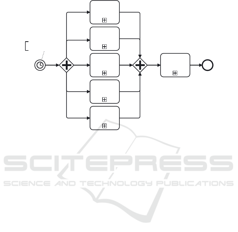
tailed BPMN diagrams. Figure 2 illustrates a concep-
tual model providing an overview of the ETL process,
specifically depicting the data load into the dimension
tables: Temporal, City, Customer, Employee, and
Product. To ensure referential integrity, dimensions
are populated first, followed by the fact tables—in
this case, the sales fact table. This dependency is rep-
resented using Parallel Gateways, which do not nec-
essarily enforce parallel execution but rather indicate
the independence of tasks.
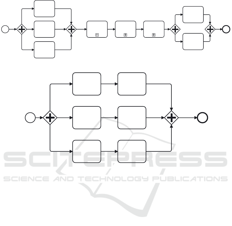
Following a hierarchical modeling, each child-
level process is depicted in a separate diagram, linked
to a subprocess activity referenced in the high-level
diagram. The sub process ”Load Customer Dimen-
sion” is presented in Figure 3. A detailed sub pro-
cess for Customer Dimension Loading consists of
performing three support tasks:
• Update Lineage Table: This activity logs the start
time of the ETL process, capturing when the data
loading operation begins. Once the process com-
pletes, the lineage table is updated again to record
the completion time, ensuring a detailed audit trail
of the data ingestion process.
• Clear Staging Table: This activity ensures that
the staging area is properly prepared for new
data ingestion by removing outdated or temporary
records from previous ETL runs. Since the stag-
ing table acts as an intermediary storage space be-
fore loading data into the target system, clearing
it prevents duplication, inconsistencies, and data
conflicts.
• Get Last ETL Cutoff Time: This step retrieves the
cutoff timestamp, which defines the starting point
for extracting new or updated customer records
from the source system. The cutoff time is stored
in a metadata or control table and represents the
last successful ETL execution. By using this
timestamp, the process ensures that only new or
modified customer records since the last data load
are extracted, optimizing performance and pre-
venting redundant data processing.
ICEIS 2025 - 27th International Conference on Enterprise Information Systems
164
Load Temporal
Dimension
Load Customer
Dimension
Load City
Dimension
Load City
Employee
Load Products
Load Sales
Fact
EndStart
Daily at 23:00pm
Figure 2: BPMN general conceptual model - Level 1.
Figure 2: BPMN general conceptual model - Level 1.
• Extract Customer Data: Identifies and loads Cus-
tomer data
• Load Customer Dimension: Stores transformed
data into the target dimension.
Subprocesses in BPMN are essential for creating
hierarchical abstraction levels, simplifying model rep-
resentation through a top-down approach. Any task
that can be further decomposed should be modeled
as a subprocess, while atomic activities should re-
main as individual tasks. The ”Load Customer Data
to DSA” subprocess consists of identifying changes
in customer data for further transformation and clean
(”Transform Customer Data”). The ”Load Customer
Dimension” sub process loads the data to Dimension
and the Lineage Table is updated.
The expansion of the ”Extract Customer Data”
subprocess is shown in Figure 4. It consists of
four subprocesses focused on identifying changes re-
lated to customers, including: Changes in purchase
groups table, Changes in customer categories table
and Changes in customer records table. These activ-
ities are powered by Change Data Capture (CDC), a
technique used to efficiently detect and track changes
in source tables. CDC ensures that only the new
or modified data since the last update is captured,
preventing the unnecessary extraction of unchanged
data and improving the overall performance of the
ETL process. These tasks ensure that only the rele-
vant customer data (new or changed) is extracted and
staged for further processing, allowing efficient data
management and ensuring the target database reflects
the most up-to-date customer information. The final
tasks involve update CutOff time and the Lineage ta-
ble. Level 2 Modeling, or Analytical Modeling, in-
volves a detailed representation of the ETL process
designed for interpretation by advanced users. As the
level of abstraction increases, so does the complexity
of the model. To elaborate on the details of the ETL
flow, new elements, such as annotations and data ob-
jects, are added. Annotation elements should include
the following. Input data for the activity (input), de-
scription of the task’s functionality (description), and
output data from the activity (output). Each process
should be documented in as much detail as possible,
which will significantly facilitate the physical imple-
mentation and interpretation of the process. Level 2
method involves adding data objects to the already
implemented diagrams. These objects represent the
states of data flowing within a process, whether they
are data inputs, data outputs, or data storage.
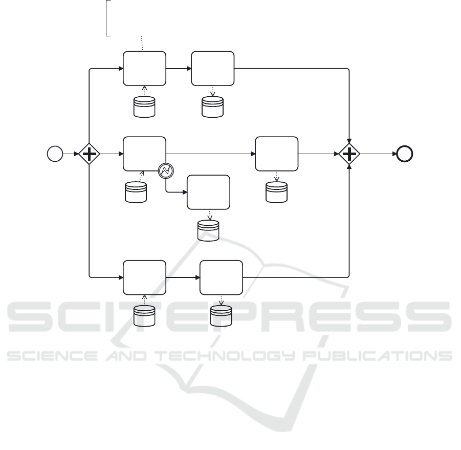
Figure 5 provides a detailed view of the concep-
tual model shown in Figure 3 for Load Customer Data
to DSA. In this expanded version, database objects
corresponding to the data sources and destinations in-
volved in the Change Data Capture (CDC) tasks are
included. This expansion enhances the model by of-
fering a more granular representation of the process
flow, showcasing how data is captured, transformed,
and loaded between various system components, in-
cluding the source and target databases. Additionally,
Business Process Modeling Techniques for Data Integration Conceptual Modeling
165
Start
Update ETL
Lineage Table
Clean Data
Staging Table
Get Last ETL
CutOff Time
Update Last
ETL CutOff
Time
Update ETL
Lineage Table
Transform
Customer Data
Load Customer
Dimension
Load Customer
Data to DSA
End
Figure 3: Load Customer Data sub-process Conceptual Model
Figure 3: Load Customer Data sub-process Conceptual Model.
EndStart
CDC Buying
Groups
CDC Customer
CDC Customer
Category
Load Staging
Buying Groups
Load Staging
Customer
Load Staging
Customer
Figure 4: Load Customer Data sub process Conceptual Model.
parameterized annotations are incorporated from the
child-level expansion to provide implementers with a
clearer understanding of the ETL activities. These an-
notations offer valuable details, including the purpose
of each task, the input data, and the expected output
data. The ”Command” field is also utilized to add
specific metadata, which can be leveraged later dur-
ing the actual process implementation.
A compensation intermediate event is applied to
the ”CDC Customer” task, indicating that if a cus-
tomer’s address is found to be null, that customer’s
record should be moved to a quarantine table in
the Data Staging Area (DSA). This quarantine table
serves as a temporary holding area for records that
require further validation or cleansing before being
processed further in the ETL pipeline. By isolating
problematic records in the quarantine table, the ETL
process can continue without disruption, while en-
suring that data integrity is maintained. In addition
to Input, Output, Description, and Command fields
in annotations for supporting ETL tasks in Level 2
BPMN modeling There are several other fields you
can consider adding to further enrich the ETL annota-
tion model. For example:
• Transformation Logic: Describes the specific
rules or logic applied to the data during the
”Transform” phase of ETL. This can include data
cleansing, formatting, aggregations, or any other
transformations applied to the raw input data. Ex-
ample: ”Normalize values between 0 and 100,”
”Merge data from two sources,” or ”Remove du-
plicates.”;
• Error Handling: Details how errors or exceptions
are managed within the ETL process. This is im-
portant for ensuring that the ETL process can re-
cover from failures or issues. Example: ”Address
IN NOT NULL”
• Data Source/Target: Specifies the source system
and the target system for data being extracted
or loaded. This is useful in an ETL process
where data flows between different systems or
databases. Example: ”Customer.address1 -¿ Dim-
Customer.City”.
• Performance Metrics: Provides information about
performance expectations or key metrics for the
ETL task. This can help track efficiency and op-
timize the ETL process. Example: ” ”Max allow-
able processing time: 2 hours.”
ICEIS 2025 - 27th International Conference on Enterprise Information Systems
166
CDC Buying
Groups
Load Staging
Buying Groups
CDC Customer
Load Staging
Customer
Move to
Quarantine
Load Staging
Customer
CDC Customer
Category
BuyingGroups DSA_BuyingGrou
ps
Input: BuyingGroups(BuyingGroupID, BuyingGroupName,
AddedDate), Process(lastETLCutOffTime)
Description: Identify new buying groups
Ouput: BuyingGroupID, BuyingGroupName
Command: EXEC newBuyingGroups(lastETLCutOffTime)
Categories
Null Address
DSA.Categories
DSA.CustomersCustomers
DSA.CustomerQu
arantine
EndStart
Figure 5: Load Customer Data to DSA sub process Conceptual Model.
These annotations can also be structured using
common notations, ensuring that the information is
both human-readable and machine-executable. A
JSON structure can serve as an intermediate represen-
tation, dynamically generating executable code or, at
the very least, a skeleton of an executable model. This
structured approach enables automation, consistency,
and maintainability in ETL processes. A concrete
example of this approach can be seen in SSIS, one
of the most widely used traditional ETL tools. Fig-
ure 6 presents a JSON representing for ”CDC Buying
Groups”. It can be translated to a physical model us-
ing BIML (Business Intelligence Markup Language).
BIML is an XML-based language that allows devel-
opers to define SSIS packages programmatically. By
structuring annotations in JSON, we can automate the
translation into BIML, which in turn generates a fully
functional SSIS package.
In ETL modeling, data annotations need to be
highly specific to ensure that the transformation logic,
error handling, and data mappings are clear and exe-
cutable. Unstructured text is generally avoided be-
cause it introduces ambiguity, making it difficult to
translate into executable primitives. When annota-
tions are too vague or flexible, misunderstandings
can arise, leading to inconsistencies between con-
ceptual models and their physical implementations.
On the other hand, if we over-detail data annota-
tions, we essentially create a custom configuration
language. While this increases precision, it also in-
troduces complexity—users may find that once a lan-
guage becomes too structured, it is more efficient to
directly use well-known technical languages such as
SQL, Python, or specific ETL scripting languages.
This creates a trade-off between abstraction and us-
ability. In the age of Artificial Intelligence (AI), more
abstract annotations can be leveraged as prompts for
AI agents. These agents can validate the annotations
against execution requirements, disambiguate unclear
transformations or mappings, and assist users in gen-
erating physical ETL models from high-level specifi-
cations. AI can also work in reverse: once a physical
model (e.g., a Microsoft Integration Services - SSIS
package) is generated, a trained AI agent can map it
back to conceptual primitives, ensuring that the doc-
umentation remains synchronized with the evolving
project. This bi-directional mapping helps maintain
consistency and improves collaboration between busi-
Business Process Modeling Techniques for Data Integration Conceptual Modeling
167

Figure 6: Example JSON structure for representing data an-
notations.
ness users and technical teams. This two-way map-
ping (from conceptual to executable and vice versa)
helps in model-driven development, where business
logic and technical implementation stay in sync.
5 CONCLUSIONS
Data pipelines are often the most complex and time-
consuming aspect of building data systems. Many
tools are available, each offering specific features to
facilitate data processing, but the complexity of the
processes still presents challenges. Activities like ex-
traction, transformation, and loading (ETL) can be
represented in various ways, often implemented in
multiple languages, leading to intricate designs.
Designing an efficient, error-free data pipeline is
a resource-intensive task, and despite extensive re-
search, there is no consensus on best practices for
modeling them. Different methods, including UML,
BPMN, and proprietary models, have been proposed,
but no standardized structure for data pipeline work-
flows exists. A structure that reduces the program-
ming workload in design, optimization, and main-
tenance is necessary, offering recommendations for
aligning with business requirements and enhancing
performance.
BPMN provides a method for translating busi-
ness requirements into a conceptual model, indepen-
dent of specific tools. However, no single standard
has emerged for conceptualizing data pipelines, and
existing approaches require significant developer in-
put and business user validation. BPMN simpli-
fies data pipeline representation with a well-known
language, focusing on core process aspects without
technical details. However, it can create inconsis-
tencies, as the same process can be modeled dif-
ferently. A structured approach reduces redundancy
and enhances clarity, validated in the context of data
pipelines.
The proposed approach offers general rules for
solving problems, regardless of context or implemen-
tation tool. It bridges the conceptual model and phys-
ical implementation, providing detailed documenta-
tion for both business and advanced users. The ap-
proach draws from pioneering work in BPMN ap-
plied to data pipelines, including three levels of rep-
resentation: Descriptive, Analytical, and Executable
Modeling. BPMN enables multi-perspective design
but may introduce ambiguity in execution, which this
work aims to address through a methodology offering
guidelines and best practices. Future research could
involve modeling real-world pipeline scenarios to val-
idate and refine the approach.
The approach presented can also help to bridge the
gap between conceptual models and physical plans,
enhancing the value of conceptual modeling in under-
standing and implementing data pipelines. It provides
a solid foundation for physical implementation, which
can be enriched with ”physical” details while keeping
process logic at higher levels. While this paper ex-
plores how structured metadata can be leveraged to
generate ETL implementations (e.g., using BIML for
SSIS), it does not cover AI-driven translation due to
scope and space limitations. However, future work
could focus on:
• Developing AI models capable of translating
physical ETL implementations back into concep-
tual primitives.
• Creating AI-assisted ETL design tools that inter-
actively guide users in refining and validating an-
notations.
• Exploring model synchronization techniques to
ensure that business logic and technical imple-
mentations remain aligned throughout the project
lifecycle.
ICEIS 2025 - 27th International Conference on Enterprise Information Systems
168

This integration of AI-driven ETL modeling could
significantly improve ETL design, making it more
flexible, automated, and easier to maintain over time.
ACKNOWLEDGEMENTS
This work has been supported by national funds
through FCT - Fundac¸
˜
ao para a Ci
ˆ
encia e Tec-
nologia through projects UIDB/04728/2020 and
UIDP/04728/2020.
REFERENCES
Aagesen, G. and Krogstie, J. (2015). BPMN 2.0 for Mod-
eling Business Processes, pages 219–250. Springer
Berlin Heidelberg.
Akkaoui, Z. E. and Zimanyi, E. (2009). Defining etl worfk-
lows using bpmn and bpel. In Proceeding of the ACM
twelfth international workshop on Data warehousing
and OLAP DOLAP 09, pages 41–48. ACM.
Biswas, N., Chattapadhyay, S., Mahapatra, G., Chatterjee,
S., and Mondal, K. C. (2019). A new approach for
conceptual extraction-transformation-loading process
modeling. International Journal of Ambient Comput-
ing and Intelligence, 10:30–45.
Biswas, N., Chattopadhyay, S., and Mahapatra, G. (2017).
Sysml based conceptual etl process modeling. In
International Conference on Computational Intel-
ligence, Communications, and Business Analytics,
pages 242–255. Springer Singapore.
Dayal, U., Castellanos, M., Simitsis, A., and Wilkinson,
K. (2009). Data integration flows for business in-
telligence. In Proceedings of the 12th International
Conference on Extending Database Technology: Ad-
vances in Database Technology, pages 1–11. ACM.
Dupor, S. and Jovanovi, V. (2014). An approach to concep-
tual modelling of etl processes. In 37th International
Convention on Information and Communication Tech-
nology, Electronics and Microelectronics (MIPRO).
IEEE.
Inmon, B. (2016). Data Lake Architecture: Designing the
Data Lake and Avoiding the Garbage Dump. Technics
Publications; 1st edition.
Janssen, M., van der Voort, H., and Wahyudi, A. (2017).
Factors influencing big data decision-making quality.
Journal of Business Research, 70:338–345.
Kimball, R. and Caserta, J. (2004). The Data Warehouse
ETL Toolkit: Practical Techniques for Extracting,
Cleaning, Conforming, and Delivering Data. John
Wiley & Sons, Inc.
Lenzerini, M. (2002). Data integration. In Proceedings
of the twenty-first ACM SIGMOD-SIGACT-SIGART
symposium on Principles of database systems, pages
233–246. ACM.
Munappy, A. R., Bosch, J., and Olsson, H. H. (2020). Data
Pipeline Management in Practice: Challenges and
Opportunities, pages 168–184. Springer-Verlag.
Nwokeji, J. C. and Matovu, R. (2021). A Systematic Liter-
ature Review on Big Data Extraction, Transformation
and Loading (ETL), pages 308–324. Springer, Cham.
Oliveira, B., Oliveira, O., and Belo, O. (2021). Using bpmn
for etl conceptual modelling: A case study. In Van-
DerAalst, W., editor, Proceedings of the 10th Interna-
tional Conference on Data Science, Technology and
Applications (DATA), pages 267–274. SCITEPRESS.
Citations/Indexing: crossref, dblp, scopus: 0, wos: 0.
Oliveira, B., Santos, V., Gomes, C., Marques, R., and
Belo, O. (2015). Conceptual-physical bridging - from
bpmn models to physical implementations on ket-
tle. In Daniel, F. and Zugal, S., editors, CEUR
Workshop Proceedings, volume 1418, pages 55–59.
CEUR-WS.org.
Prakash, G. H. and Rangdale, S. (2017). Etl data con-
version: Extraction, transformation and loading data
conversion. International Journal of Engineering and
Computer Science, 6:22545–22550.
Raj, A., Bosch, J., Olsson, H. H., and Wang, T. J. (2020).
Modelling data pipelines. In 46th Euromicro Confer-
ence on Software Engineering and Advanced Applica-
tions, SEAA, pages 13–20. IEEE.
Silver, B. (2011). Bpmn Method and Style: A Levels-Based
Methodology for Bpm Process Modeling and Improve-
ment Using Bpmn 2.0. Cody-Cassidy Press, second
edition edition.
Soffer, P., Kaner, M., and Wand, Y. (2012). Towards Un-
derstanding the Process of Process Modeling: Theo-
retical and Empirical Considerations, pages 357–369.
Springer, Berlin, Heidelberg.
Souibgui, M., Atigui, F., Zammali, S., Cherfi, S., and Yahia,
S. B. (2019). Data quality in etl process: A prelim-
inary study. Procedia Computer Science, 159:676–
687.
Trujillo and Luj
´
an-Mora, S. (2003). A uml based approach
for modeling etl processes in data warehouses. Con-
ceptual Modeling - ER 2003 - Lecture Notes in Com-
puter Science, 2813:307–320.
Vassiliadis, P., Simitsis, A., Georgantas, P., Terrovitis, M.,
and Skiadopoulos, S. (2005). A generic and customiz-
able framework for the design of etl scenarios. Infor-
mation Systems, 30:492–525.
Yaqoob, I., Hashem, I. A. T., Gani, A., Mokhtar, S., Ahmed,
E., Anuar, N. B., and Vasilakos, A. V. (2016). Big
data: From beginning to future. International Journal
of Information Management, 36:1231–1247.
Business Process Modeling Techniques for Data Integration Conceptual Modeling
169
