
Digital Twin Concept for a Novel Aerosol-on-Demand Jet-Printing
System
Hanna Pfannenstiel and Ingo Sieber
a
Institute for Automation and Applied Informatics, KIT, Hermann-von-Helmholtz-Platz 1, 76344 Eggenstein-Leopoldshafen,
Germany
Keywords: Digital Twin, Modelling, Simulation, Additive Manufacturing, Aerosol Jet-Printing System, Machine
Learning.
Abstract: In this article, we present the concept and architecture of a digital twin (DT) used for the development and
subsequent control and operation of a novel aerosol-on-demand (AoD) jet-printing system. Since the process
of aerosol generation used in the AoD printing process has many complex interactions that can hardly be
described by established theories, this paper develops an architecture that enables the digital image to learn
from its physical counterpart. Conventional DT architectures only allow the use of digital twins if they can
mimic their physical counterpart accurately. Our approach overcomes this limitation by enabling the digital
twin to learn empirically and thereby improve its models by using a data loop.
1 INTRODUCTION
Digital twin (DT) technology is commonly described
in both academia and industry as a combination of a
physical entity, a virtual counterpart, and a data link
between the two. In this context, the digital twin is a
digital representation of a system in operation,
consisting of its main characteristics, attributes and
behaviors. (Stark & Damerau, 2019). Digital twins
have many definitions depending on the context they
are used in (Glaessgen & Stargel, 2012; Grieves,
2014; Grieves & Vickers, 2017; Rosen et al., 2015;
Tao et al., 2018; Kritzinger et al., 2018; Autiosalo et
al., 2020). DT is of great importance in the production
context as it offers the possibility to improve
production processes, adjust production processes to
other, new means of production, confirm settings and
find new operating points and simulate situations to
predict performance (Roy et al., 2020).
The development of printed electronics is based
increasingly on the functional printing of novel
nanomaterials (Das & He, 2021; Suganuma, 2014;
Wu, 2017; Choi et al., 2015, Magdassi & Kamyshny,
2017), as the use of inks with special chemical,
physical, or optical properties enables the production
of novel functional structures (Sirringhaus &
a
https://orcid.org/0000-0003-2811-7852
Shimoda, 2003; Sieber et al., 2020; Sieber et al.,
2021; Magdassi, 2010). Printed functional elements
such as conductive tracks or electronic components
like resistors and transistors require high quality in
terms of line width, edges, and layer thickness to
ensure reproducible electrical properties
(Subramanian et al., 2008). One promising concept in
this context is aerosol jet printing, where functional
ink is atomized into a fine spray and then transformed
into a stable and over several millimeters well-
collimated aerosol jet through hydrodynamic
focusing by a sheath gas flow (Ganz et al., 2016,
Gupta et al., 2016). Due to this collimation range, the
distance between the substrate and the print head can
be varied without significantly changing the line
width. This is also why aerosol-based printing
processes, unlike inkjet printing, are suitable for
printing on 2.5D and 3D components (Neotech,
2025).
Recently, the authors presented a new principle
for aerosol-jet-on-demand printing, the core of which
is an atomization unit integrated directly inside the
printhead (Ungerer et al., 2023a). This enables a
compact system design, printing operation in all
spatial directions, widely tunable distance between
printhead and substrate, as well as jet-on demand
mode of operation (Sieber et al., 2022). This new
Pfannenstiel, H., Sieber and I.
Digital Twin Concept for a Novel Aerosol-on-Demand Jet-Printing System.
DOI: 10.5220/0013459200003970
In Proceedings of the 15th International Conference on Simulation and Modeling Methodologies, Technologies and Applications (SIMULTECH 2025), pages 201-208
ISBN: 978-989-758-759-7; ISSN: 2184-2841
Copyright © 2025 by Paper published under CC license (CC BY-NC-ND 4.0)
201
method of achieving an AoD printing process exhibits
many complex interactions that are difficult to
describe with conventional theory. Insights into the
function of atomization require physical tests on the
laboratory setup. These are difficult to perform and
interpret due to the complex flow conditions in the
AoD printhead. Previous attempts to measure the
aerosol flow field using Particle Shadow Velocimetry
(PSV) have shown that the small droplet size
combined with a highly complex velocity field makes
the measurements inaccurate (Pöppe, 2023; Ungerer
et al., 2022).
This paper aims to describe the concept and
architecture for a DT of the AoD, as well as to present
and discuss approaches to model reduction and shows
which subsystems are necessary in the DT and how
they interact.
The structure of this paper is: Section 2 presents
the patented AoD jet-printhead as well as the current
lab setup, acting as part of the physical layer, Section
3 deals with the models describing the functioning of
the printhead as well as approaches to model
reduction. In Section 4 the DT is presented. Here the
concept as well as the specific architecture are shown.
Section 5 closes the paper with conclusions and gives
an outlook over further planned work.
2 SETUP OF THE AoD
JET-PRINTING SYSTEM
2.1 The AoD Jet-Printhead
The primary feature of the novel concept of the AoD-
jet printhead is the integration of the atomization
process into the printhead (Ungerer et al., 2023a).
This enables a compact system design, printing
operation in all spatial directions, widely tunable
distance between printhead and substrate, as well as
jet-on demand mode of operation (Sieber et al., 2022).
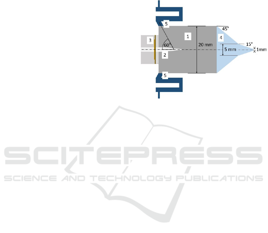
Fig. 1 shows a schematic of the printhead with all its
main components. Aerosol generation takes place by
excitation of a fluid inside a glass capillary (2) by
means of a piezo actuator (3). The aerosol spray flows
into the mixing chamber (1) where it is
aerodynamically focused by an inflowing sheath gas
and the nozzle (4). The sheath gas flows into the
mixing chamber by four inlets which are arranged
equidistantly around the circumference. The four
inlet channels, from which only two are depicted in
Figure 1, have a meandering structure (5). The
deflection in the channel bends causes additional
mixing so that the velocity profiles of the sheath gas
are homogenised within the mixing chamber (Sieber
et al., 2022).
Figure 1: Schematic of the principle design of the AoD-jet
print head.
2.2 Lab Setup of the AoD Jet-Printing
System
The existing laboratory setup is still under
development, its current implementation is shown in
Figure 2. It consists of the printhead with atomization
unit and nozzle, a frequency generator, an ink
reservoir with pressure control and mass flow sensor,
a high-power LED, and a high-speed camera.
Pressure control of the ink reservoir is carried out by
an Ultimus II dispenser from Nordson, while the mass
flow of the ink during operation of the printhead is
measured between the reservoir and the printhead by
a mass flow sensor (SLG-0150, Sensirion,
Switzerland). The printhead is connected to a
frequency generator (SDG2000X, Siglent
Technologies CO) to provide the required frequency
for atomization. The piezo actuator is directly
connected to the capillary. Focusing of the aerosol
spray is done by interaction of the inner contour of the
nozzle and the mass flow of the sheath gas. The flow
rate of the sheath gas is controlled by the mass flow
controller (red-y smart controller GSC, Vögtlin). To
monitor the quality of the aerosol jet and the droplet
distribution, the setup includes a high-speed camera
(EoSens 3CXP Mikrotron, SVS-Vistek GmbH) and a
light microscope (VHX-7020, Keyence). This allows
the monitoring and control of the printing process
exclusively by optical methods to ensure the desired
quality is achieved.
SIMULTECH 2025 - 15th International Conference on Simulation and Modeling Methodologies, Technologies and Applications
202
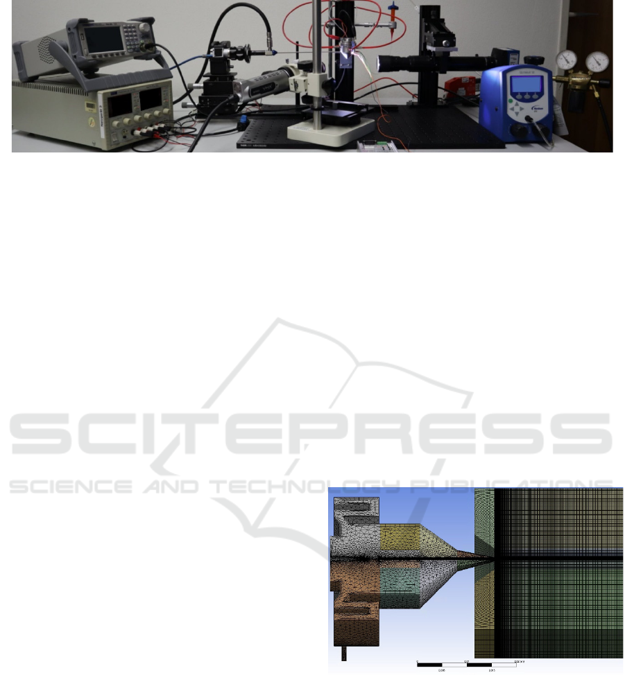
Figure 2: Laboratory setup of the AoD testbed.
3 MODELLING
In order to develop and design the patented concept
of the AoD printhead, a CFD model of the printhead
is implemented and used for design optimization of
the printhead with respect to its manufacturability in
our in-house workshop (Ungerer et al., 2023b).
Simulation results not only lead to the design but also
gives preliminary operation parameters. Ansys Fluent
in its versions R19.3, R20.1, and 2024 R2 is used for
fluid dynamic calculations. When modelling the ink,
the Euler-Lagrange model is used, which includes a
particle-based approach to the discrete phase (Sieber
et al., 2022).
The generated aerosol is modelled in Fluent using
a cone model, which means that the generated aerosol
is described by its origin, the cone axis, the cone
angle, the radius, the diameter of the droplets, the
diameter distribution, the exit velocity of the droplets
and the aerosol mass flow rate (Ungerer et al., 2023c).
The mesh used for the CFD calculations was
optimised using a mesh independence study resulting
in 2.1 ∙ 10
elements (Ungerer et al., 2023c). Since
the Euler-Lagrange model used is a particle-based
consideration of the discrete phase, it must be ensured
that a particle can, in principle, be completely
contained within a mesh element. To increase the
resolution in the atomization zone, i.e., in the area
between the capillary and the nozzle outlet, while
maintaining this condition with a droplet diameter of
approximately 20 µm, an element size of 33 µm is
used (see Fig. 3) (Ungerer et al., 2024)
Due to the complexity of the model, the CFD
simulations require many hours to a few days for
calculation (the CFD simulations are carried out on a
workstation equipped with AMD Ryzen Threadripper
3970X processor with 32 cores, 64 threads @
3.7 GHz, 128 GB RAM, and an Nvidia Titan RTX
graphics processor with 24 GB). One goal of the DT
is to provide the user with recommendations for
optimal settings. This must be done based on
simulations. For this reason, a computationally
efficient model is required that can represent all
relevant aspects of the underlying CFD model. Since
the DT regularly updates its CFD models when new
data becomes available over the course of the
printer’s lifecycle the algorithm must also be able to
autonomously reduce the models every time they are
updated. For this purpose, various approaches to
model reduction are investigated, namely polynomial
regression (Pfannenstiel et al., 2024a) and the
Gaussian method (Pfannenstiel et al., 2024b), with
the aim of autonomously determining properties of
the aerosol jet solely through its initial injection
parameters. The goal of this ongoing work is to
autonomously create a reduced model that comes as
close as possible to the computationally intensive
CFD simulation and can be used inline by the DT.
Figure 3: Meshed geometry model of the printhead and a
free space area (Ungerer et al., 2023c).
4 DIGITAL TWIN
4.1 Digital Twin Concept
Essential for putting the newly developed concept of
the aerosol printhead into operation is the
determination of the control parameters and an
Digital Twin Concept for a Novel Aerosol-on-Demand Jet-Printing System
203
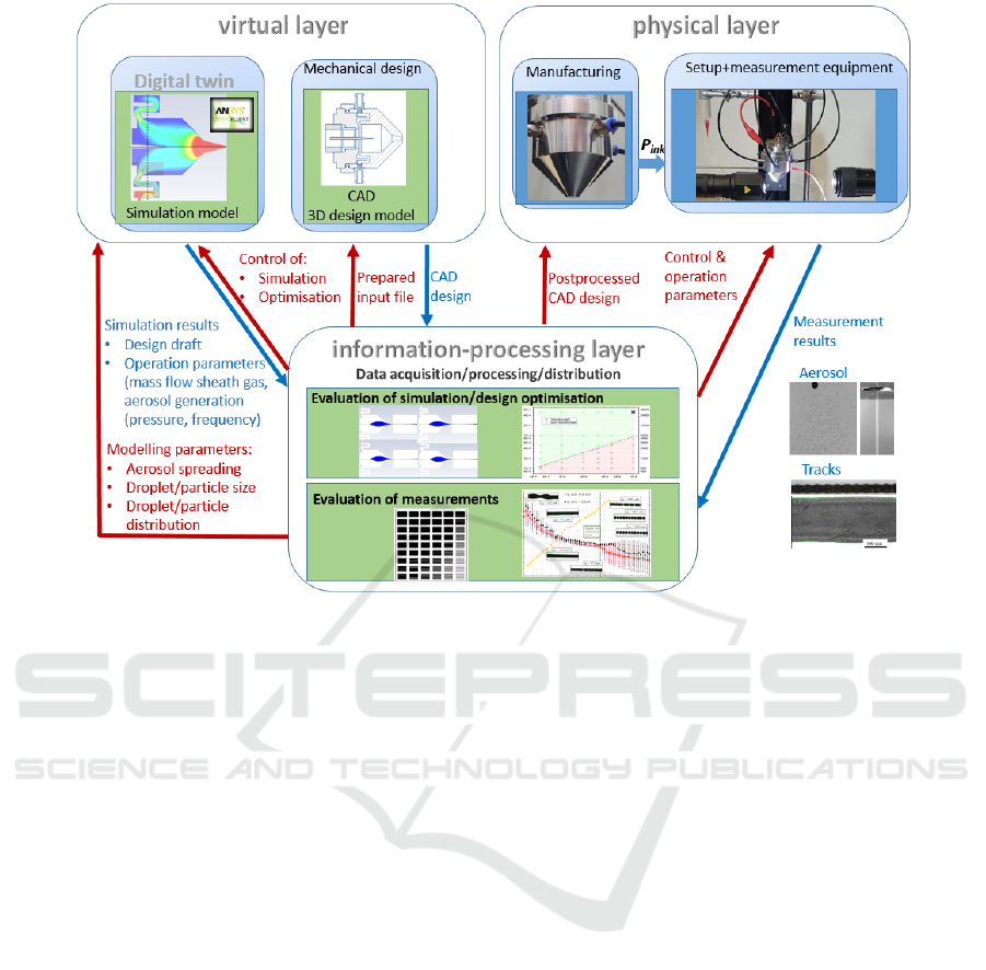
Figure 4: Three-layer concept of the Digital Twin.
adapted chamber design for a proper function. A
problem herein is the contamination of the inner walls
of the manufactured printhead with ink due to non-
optimal control parameters or non-optimal geometry
of the chamber design of the printhead, both leading
to wall contact of the ink spray (Sieber et al., 2022).
Such contaminations would lead to difficult and time-
consuming cleaning processes on the real component.
Determination of ink-specific operation parameters
as well as an adaptation of the chamber design to
specific ink formulations is one task of our digital
twin concept, which is based on a three-layer design.
The virtual layer (VL) is linked to the physical layer
(PL) by an information-processing layer (IPL) (see
Fig. 1). The bidirectional mapping and
interoperability of the physical and the virtual space
are realized through data interaction (Zheng et al.,
2019).
The VL consists of a simulation model of the
printhead, which is implemented using computational
fluid dynamic (CFD) and a 3D CAD (computer-aided
design)-model. The manufacturing of the printhead as
well as the laboratory setup and the measurement
equipment is located in the PL. Mapping of virtual
and physical layer is conducted by the IPL by means
of data analysis, derivation of control parameters for
the digital and the physical twin, as well as a quality
control. Input of the VL to the IPL are the ink-specific
simulation results like e.g. operation parameters,
design parameters, and control parameters. Analysis
and evaluation of the simulation results take place in
the IPL with respect to the defined criteria, like, e.g.
non-wetting condition of the inner walls of the
printhead, avoidance of turbulences by limiting the
Reynolds number to below 1200 (which is controlled
by the mass flow of the sheath gas used for
aerodynamical focusing), a stable, focused and
collimated aerosol jet, and design rules of the
manufacturing processes used. Based on the analysis
and evaluation results design optimization is
controlled. Once the optimized design together with
the respective control and operation parameters are
achieved, a preprocessed file of the initial design-for-
manufacture of an aerosol-on-demand printhead,
designed for one specific ink formulation is generated
as input to the CAD tool in the VL. Here the final
CAD 3D model is constructed, send to the IPL where
postprocessing is conducted. The postprocessed file
is digital input to the part manufacture in the PL. Up
to this transfer, the printhead is entirely described
digitally. After the manufacturing process, a real part
of the ink specific printhead P
ink
exists. The
manufactured printhead is installed in a laboratory
and measurement setup and set into operation with
the (in the IPL derived) control and operation
parameters. In-operation measurements were carried
SIMULTECH 2025 - 15th International Conference on Simulation and Modeling Methodologies, Technologies and Applications
204

out with respect to aerosol generation and by
inspection of the printed tracks. The resulting data of
the measurement again are digital descriptions and
input into the IPL. Measurement data are used in two
ways:
1. To control the quality of the printed
structures (and, hence, validate the
simulation model).
2. To derive model parameters of the discrete
phase.
The line morphology of the printed lines is
examined using image processing methods. With the
help of the line width, line density, smoothness of the
edges and overspray, statements are made about the
quality of the printed lines. Based on the
measurement results, a model validation is conducted
in the VL in two respects: On the one side the
inspection of the printed track is used for quality
control and to validate the operation parameter, on the
other side, the measurement data of the aerosol spray
are used to enhance the model of the discrete phase.
This validation step qualifies the CFD model of the
aerosol-on-demand printhead for use as a digital twin.
4.2 Digital Twin Architecture
Based on this concept of a digital twin, an architecture
for a comprehensive DT is being developed, which
clearly defines and structures the individual
subsystems and their interactions. This also takes into
account the manufacturing tolerances of the
individual physical components of the AoD-jet
printing system, as well as the autonomously running
model reduction, which avoids time-consuming CFD
simulations by generating simpler models that
estimate the initial printing control parameters from
input parameter sets of the CFD models (Ungerer et
al. 2024; Pfannenstiel et al., 2024a; Pfannenstiel at al.,
2024b).
The architecture of the digital twin proposed in
this paper consists of two types of digital twins as a
kind of subsystems, following a definition by Grieves
(Grieves, 2023). These are the digital twin prototype
and the digital twin instance. We apply this concept
both to the components that make up the real AoD
setup or are used in the printing process and to the
printing process itself.
Our new principle of the AoD printing process
features many complex interactions that are hardly
describable by established theory. Physical tests
necessary to gain an understanding of the atomization
process have shown to be difficult to perform on the
AoD printhead (Pfannenstiel at al., 2024b).
The comprehensive DT architecture is also based
on a three-layer architecture consisting of a Physical
Layer (PL), a Virtual Layer (VL) and an Information
Processing Layer (IPL) (see Fig. 4) and embeds
definitions of Grieves who has established the use of
DTs in the Product Lifecycle Quality (PLQ) loop
where DTs can be used to replace physical tests
(Grieves, 2023). Grieves introduces the Digital Twin
Prototype (DTP), which contains all information
necessary to produce a product. Before a physical
product is manufactured, tests can be done on this
virtual, idealized version of the product and the
Digital Twin Instance (DTI): When a product is
manufactured, a DTI is created which is tied to that
specific product. The DTI features all the tolerances
like e.g. imperfections and differences from the real
component to the DTP. It also stores information
about the operation of the product it is tied to.
The Physical Layer of our DT architecture
contains the printer setup and the user and is
connected to the Data Storing Layer. The basic
features of the VL are the Part DTP and the Print
DTP. In the Part DTP the information of the
components of which the AoD printing system
consists are stored (e.g. as CAD together with its
fabrication requirements, or specific inks defined by
there parameters like e.g. viscosity, particle load) and
follows very much the definition of Grieves. This
looks different with respect to the Print DTP. Because
of the high flexibility of digital additive processes,
there does not exists one ideal product. Printing
results will be dependent on ink parameters, from the
interaction of the ink and the substrate and so on.
Hence in our architecture, the Print DTP is defined as
the ideal model of the manufacturing process. Here
all the models describing the AoD printing process
are saved. These models include detailed settings for
the CFD simulation, a model that describes the
atomization as well as the recommendation
algorithm.
Combination of this set of initial conditions
simulate the specific process and its result. Since the
proposed architecture allows for model improvement,
the version of the respective model needs to be
tracked also. Instantiation of Part and Print DTP takes
place by the Part DTI and the Print DTI, respectively.
The instances of the parts of the AoD-jet printing
system consist of tolerances of the real manufactured
part used in the AoD-system and uses the data from
the corresponding Part DTP as basis. The result of
this DTI is a representation of the real component as
detailed as possible. The Print DTI is tied to a specific
printed structure and the respective printing process.
A Print DTI is created when the user initiates a
Digital Twin Concept for a Novel Aerosol-on-Demand Jet-Printing System
205
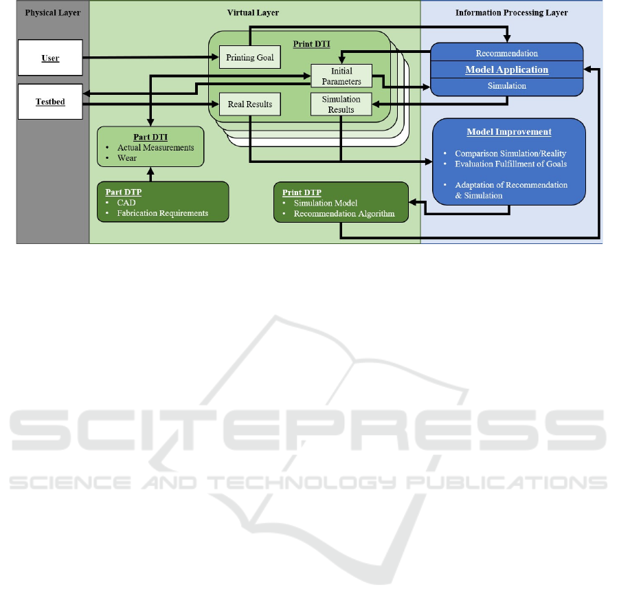
Figure 5: DT architecture to support the AoD printing process including the necessary structure to enable automated
improvement (Pfannenstiel et al. 2024b).
printing process by defining the printing goals which
are saved as a dataset in the Print DTI. The printing
goal then is input into the recommendation algorithm
(in the IPL) which deduces on basis of simulations the
set of initial parameters. The initial parameters also
take deviations of real parts used in the AoD-system
resulting from the manufacturing process into
account, depicted by the link from the Part DTI in
Figure 5, and are input into the AoD-systems control.
A simulation on basis of these initial parameter set is
carried out which enables a model improvement by a
comparison of the simulation results with the printing
results. This does not need to happen simultaneously
to the physical printing process and can be done when
there is computational power available. If the
simulation is found to be not accurate enough, an
automated method can change model settings in the
simulation in certain capacities (Pfannenstiel et al.,
2024a). Since initial conditions and results are all
saved in a DTI, the simulation can calculate the same
case with different model settings and determine
which model settings better describe reality. Based on
the best simulation model, a model reduction is
automatically initiated, on the basis of which a line
prediction and control is created. The same approach
is used for improving the recommendation algorithm.
5 CONCLUSIONS AND
OUTLOOK
In this article, we present a digital twin architecture
that uses the DTP and DTI proposed by Grieves as
subsystems. We apply this structure both to the
components that make up the printing process and to
the actual product, the printed structure. Since in the
case of highly flexible, digital, additive manufacturing
technologies, there is no definition of a SINGLE
product, but the printed structure/component depends
on a variety of different influencing factors, we use an
ideal model here. This model is constantly validated
and improved through the implementation of a data
loop during the lifetime of the DT. This approach
enables the application of this DT architecture to our
newly developed AoD-jet printing system, as the
actual atomization process is not yet fully understood
and therefore cannot be modelled. However, by
continuously comparing the printing result with its
simulation prediction, a continuous model
improvement is made, which increasingly
approximates the description of the actual effects.
The possibilities offered by the proposed DT
architecture include real-time capability, use in
design optimization, and autonomy. To achieve real-
time capability for in-line control of the printing
process, a transition from computationally intensive
CFD models to less computationally demanding
models is necessary. The basis of in-line control is
that sensor signals are read during the printing
process and input into the simplified model, thus
adjusting the control variables of the printer during
the printing process. Investigations regarding suitable
model reduction have already been conducted using
regression fitting and the Gaussian process. Future
investigations into model reduction will address
approaches that proceed more specifically in data
collection, such as Bayesian optimization.
Once the models are sufficiently trained through
the DT process to provide a detailed description of the
AoD printing process for a variety of different
SIMULTECH 2025 - 15th International Conference on Simulation and Modeling Methodologies, Technologies and Applications
206

applications, the design can be iterated using the DT.
This means that design optimization of individual
components can be carried out in the virtual layer, and
validation can be performed using digital testing.
Through the interface to the physical layer, the
manufacturing of the optimized component can then
be carried out.
In principle, the presented DT architecture also
provides autonomous control of the AoD-jet printing
process. This requires targeted further development
of the AoD-jet printing system. In this case, user
interaction would be limited to specifying the printing
goal, and the DT would autonomously send the
recommended settings to the printing system and
carry out the printing.
Additionally, further investigations are being
conducted into the model representation of the
atomization process to allow for detailed
phenomenological modelling.
ACKNOWLEDGEMENTS
The authors would like to acknowledge Achim
Wenka (IMVT, KIT) for his continuing support in the
field of computational fluid dynamics, Raissa Stella
Maffo for her work on DT, Martin Ungerer for his
conceptual work on and implementation of the AoD-
setup, Hawo Höfer (IAI, KIT) for his work on model
reduction, and Klaus-Martin Reichert (IAI, KIT) for
soft- and hardware support.
This work was supported by the program Materials
Systems Engineering of the Helmholtz Association.
REFERENCES
Stark, R.; Damerau, T. (2019). Digital Twin. In CIRP
Encyclopedia of Production Engineering; Chatti, S.,
Tolio, T., Eds.; The International Academy for
Production Engineering; Springer: Berlin, Germany,
2019
Glaessgen, E., Stargel, D. (2012). The digital twin paradigm
for future NASA an U.S. Air Force vehicles. In 53rd
IAA/ASME/ASCE/AHS/ASC Structures, Structural
Dynamics and Materials Conference, Honolulu,
Hawaii, 2012, pp. 1-14.
Grieves, M. (2014). Digital twin: manufacturing Excellence
through virtual Factory Replication. [Online].
https://www.3ds.com/fileadmin/PRODUCTS-SERVI
CES/DELMIA/PDF/Whitepaper/DELMIA-APRISO-
Digital-Twin-Whitepaper.pdf, (accessed: 18.03.2025).
Grieves, M., Vickers, J. (2017). Digital twin: mitigating
unpredictable, undesirable emergent behavior in
complex systems. In Kahlen F-J et al. (eds)
Transdisciplinary perspectives on complex systems:
new findings and approaches., Cham, Germany:
Springer, 2017, pp. 85-113
Rosen, R., von Wichert, G., Lo, G., Bettenhausen, K. D.
(2015). About the Importance of Autonomy and Digital
Twins for the Future of Manufacturing. In IFAC-
PapersOnLine, vol. 48, issue 3, 2015, pp. 567-572
Tao, F., Cheng, J., Qi, Q., Zhang, M., Zhang, H., Sui, F.
(2018). Digital twin driven product design,
manufacturing and service with big data. In The
International Journal of Advanced Manufacturing
Technology, vol 94, London, United Kingdom. Springer
London, 2018, pp. 3565-3576
Kritzinger, W., Karner, M., Traar, G., Henjes, J., Sihn, W.
(2018). Digital Twin in manufacturing: A categorical
literature review and classification. In IFAC-
PapersOnLine, vol. 51, 2018, pp. 1016-1022, doi:
10.1016/j.ifacol.2018.08.474
Autiosalo, J., Vepsäläinen, J., Viitala, R., Tammi, K.
(2020). A Feature-Based Framework for structuring
industrial Digital Twins," in IEEE Access, vol. 8, pp.
1193-1208, doi: 10.1109/ACCESS.2019. 2950507
Roy, R.B.; Mishra, D.; Pal, S.K.; Chakravarty, T.; Panda,
S.; Chandra, M.G.; Pal, A.; Misra, P.; Chakravarty, D.;
Misra, S. (2020). Digital Twin: Current scenario and
case study on manufacturing process. Int. J. Adv.
Manuf. Technol. 2020, 107, 3691-3714
Das, R., and X. He. (2021). IDTechEx: Printed, Organic
and Flexible Electronics 2020-2030: Forecasts,
Technologies, Markets. url: https://www.idtechex.com/
en/research-report/flexible-printed-and-organic-
electronics-2020-2030-forecasts-technologies-
markets/687. (accessed: 18.03.2025).
Suganuma, K. (2014). Introduction to printed electronics,
vol. 74, 1st ed. Springer Science+Buisiness Media,
2014
Wu, W. (2017). Inorganic nanomaterials for printed
electronics: a review. Nanoscale 9 (22): 7342-7372.
doi: 10.1039/C7NR01604B.
Choi, H. W., Zhou, T., Singh, M., Jabbour, G. E. (2015).
Recent developments and directions in printed
nanomaterials. In Nanoscale, 2015, pp. 3338-3355, doi:
10.1039/C4NR03915G
Magdassi, S. and A. Kamyshny . (2017). Nanomaterials for
2D and 3D printing.
Weinheim: Wiley-VCH.
Sirringhaus, H. and T. Shimoda. (2003). Inkjet Printing of
Functional Materials. MRS Bulletin 28(11): 802–806.
doi: 10.1557/mrs2003.228.
Sieber, I. R. Thelen, and U. Gengenbach. (2020).
Assessment of high-resolution 3D printed optics for the
use case of rotation optics. Opt. Express 28: 13423-
13431.
Sieber, I., R. Thelen, and U. Gengenbach. (2021).
Enhancement of High-Resolution 3D Inkjet-printing of
Optical Freeform Surfaces Using Digital Twins.
Micromachines 12(1): 35. https://doi.org/10.3390/mi12
010035.
Magdassi, S. (2010). The Chemistry of Inkjet Inks.
Singapore: World Scientific Publishing.
Digital Twin Concept for a Novel Aerosol-on-Demand Jet-Printing System
207

Subramanian V., J.B. Chang, A. de la Fuente Vornbrock,
D. C. Huang, L. Jagannathan, F. Liao, B. Mattis, S.
Molesa, D. R. Redinger, D. Soltman, et al. (2008).
Printed electronics for low-cost electronic systems:
Technology status and application development.
ESSCIRC 2008 - 34th European Solid-State Circuits
Conference, Edinburgh: 17-24, doi:
10.1109/ESSCIRC.2008.4681785.
Ganz, S., H.M. Sauer, S. Weißenseel, J. Zembron, R. Tone,
E. Dörsam, M. Schaefer, M. Schulz-Ruthenberg.
(2016). Printing and Processing Techniques. Nisato, G.,
Lupo, D., and Ganz, S. (editors): Organic and Printed
Electronics: Fundamentals and Applications: 48-116.
Singapore: Pan Stanford Publishing.
Gupta, A.A., A. Bolduc, S. G. Cloutier and R. Izquierdo.
(2016). Aerosol Jet Printing for printed electronics
rapid prototyping, IEEE International Symposium on
Circuits and Systems (ISCAS), Montreal, QC: 866-869,
doi: 10.1109/ISCAS.2016.7527378.
Neotech. (2025). 3D Printed Electronics applications
realised by Neotech AMT. url: https://neotech-
amt.com/applications. (accessed: 16.01.2025).
Ungerer, M., Hofmann, A., Scharnowell, R., Gengenbach,
U., Sieber, I., Wenka, A. (2023a). Print Head and
Printing Method – Tête d’Impression et Procédé
d’Impression, European Patent EP 3 752 365 B1, Aug.
9, 2023
Sieber, I., Zeltner, D., Ungerer, M., Wenka, A., Walter, T.,
Gengenbach, U. (2022). Design and experimental setup
of a new concept of an aerosol-on-demand print head.
In Aerosol Science and Technology, 2022, pp. 1-12,
doi: 10.1080/02786826.2021.2022094
Pöppe, D. (2023). Evaluating the Applicability of flow
measurement Techniques for characterizing the
microdroplet Flow of the Aerosolon- Demand Printer.
M.S. thesis, Institute for Automation and Applied
Informatics (IAI), Karlsruher Institute of Technology,
Karlsruhe, 2023
Ungerer, M.; Zeltner, D.; Wenka, A.; Gengenbach, U.;
Sieber, I. (2022). Modelling and Simulation of an
Aerosol-on-Demand Print Head with Computational
Fluid Dynamics. SIMULTECH 2022: Proceedings of
the 12th International Conference on Simulation and
Modeling Methodologies, Technologies and
Applications (SIMULTECH 2022), July 14-16, 2022, in
Lisbon, Portugal. Ed.: Gerd Wagner, 44–51,
SciTePress. doi:10.5220/0011258100003274
Ungerer, M., Benítez, J.L., Zeltner, D., Wenka, A.,
Gengenbach, U., Sieber, I. (2023b). Modelling and
Design-for-Manufacturing of an Aerosol-on-Demand
Jet-Printhead. In: Wagner, G.,Werner, F., De Rango, F.
(eds), Simulation and Modeling Methodologies,
Technologies and Applications. SIMULTECH2022.
Lecture Notes in Networks and Systems, vol 780.
Springer, Cham (2023). https://doi.org/10.1007/978-3-
031-43824-0_1
Ungerer, M., Walter, T., Sieber, I. (2023c). Position
analysis of the atomiser unit of an aerosol-on-demand
jet-printhead by means of computational fluid
dynamics. SIMULTECH 2023: Proceedings of the 13th
International Conference on Simulation and Modeling
Methodologies, Technologies and Applications, (2023).
SciTePress. https://doi.org/10.5220/ 0012131000003546
Ungerer, M., Walter, T.P., Sieber, I. (2024). Tolerancing of
the Atomiser Unit of an Aerosol-on-Demand Jet-
Printhead. In: Wagner, G., Werner, F., De Rango, F.
(eds) Simulation and Modeling Methodologies,
Technologies and Applications. SIMULTECH 2023.
Lecture Notes in Networks and Systems, vol 1211.
Springer, Cham. https://doi.org/10.1007/978-3-031-
77603-8_4.
Pfannenstiel, H., Ungerer, M., Sieber, I. (2024a). Method
for automated parametric Studies and Evaluation using
the Example of an Aerosolon- Demand Jet-Printhead,
2024. SIMULTECH 2024: Proceedings of the 14th
International Conference on Simulation and Modeling
Methodologies, Technologies and Applications. Ed.: F.
De Rango, 69–79, SciTePress. doi:10.5220/001275810
0003758
Pfannenstiel, H., Höfer, H., Ungerer, M., Sieber, I. (2025).
Usage of a Gaussian Process to automatically create a
reduced Model of the Particle Behavior in an Aerosol-
on-Demand Printer. accepted by LNNS series, in press.
Zheng, Y.; Yang, S.; Cheng, H. (2019). An application
framework of digital twin and its case study. J. Ambient.
Intell. Humaniz. Comput. 2019, 10, 1141–1153.
Pfannenstiel, H., Ungerer, M., and Sieber, I. (2024b).
Digital twin architecture to use for optimizing an AoD-
printing process. In 2024 Symposium on Design, Test,
Integration and Packaging of MEMS/MOEMS (DTIP),
pages 1–5, doi:10.1109/DTIP62575.2024.10613180.
Grieves, M. (2023). Digital Twin certified: employing
virtual Testing of Digital Twins in Manufacturing to
ensure quality Products. In Machines, vol. 11, issue 8,
808, 2023. doi: 10.3390/machines11080808
SIMULTECH 2025 - 15th International Conference on Simulation and Modeling Methodologies, Technologies and Applications
208
