
A New Numerical Method for Fast Prediction of Wheel Tread Wear
for Stacker Cranes
Minggong Yu
a
, Enming Zhang
b
and Johannes Fottner
c
Chair of Materials Handling, Material Flow, Logistics, Technical University of Munich,
Boltzmannstrasse 15, 85748 Garching near Munich, Germany
Keywords: Wheel-Rail Contact, Wear Prediction, Stacker Crane, Wheel Profile Update, Co-Simulation.
Abstract: With the development of the logistics industry, the demand for efficient, high-capacity material handling
equipment, such as stacker cranes, has grown significantly. As a critical load-bearing component of stacker
cranes, the wheel-rail contact system is subtracted to higher operational speeds and load capacities, which
lead to increased contact stresses and wheel tread wear. The degraded wheel profile caused by wear can
deteriorate wheel-rail interactions, exacerbate vibrations, and subsequently reduce the lifespan of stacker
cranes. This paper proposes a numerical model based on co-simulation to predict wheel tread wear of stacker
cranes. The model combines a multibody dynamics model of the stacker crane, a wheel-rail contact model,
and a worn profile update model. Additionally, a wear superposition method, i.e., a simplified and practical
method, is developed to calculate the accumulated wear, enabling the prediction of the wheel wear under
different work cycles with limited simulation iterations. The results show the accumulated wheel tread wear
depth across various work cycles of stacker cranes, providing quantitative predictions while significantly
reducing simulation time.
1 INTRODUCTION
Stacker cranes are essential components of modern
intralogistics systems, which enable automated
storage and retrieval operations for a wide range of
goods in automated pallet and small-parts
warehouses. As rail-mounted, single-track material
handling equipment, their performance heavily relies
on the reliability of the wheel-rail system. Over the
past decade, the rapid growth of e-commerce and
globalisation has more than doubled the turnover of
the logistics industry (Achouch et al., 2022). To meet
this demand, warehousing operations have
significantly enhanced material handling efficiency.
However, this progress has pushed automated
warehouse systems, particularly stacker cranes, to
operate at their dynamic limits. The resulting increase
in dynamic loads places substantial contact stresses
on the wheel-rail system, accelerating wear and
increasing the risk of damage (Laile & Fottner, 2021).
Wear is a primary damage type affecting the
wheel-rail system, characterised by material loss due
a
https://orcid.org/0009-0005-8866-0373
b
https://orcid.org/0009-0008-1177-8404
c
https://orcid.org/0000-0001-6392-0371
to adhesive and abrasive phenomena (Tunna et al.,
2007). This material loss degrades the wheel and rail
profiles, changing the position and size of the contact
area. These changes influence the distribution of
normal and tangential forces within the contact area,
negatively impacting the system’s dynamic response.
Additionally, wear can lead to wheel out-of-
roundness, causing shock loads and vibrations during
operation. These effects may further damage other
system components (Iwnicki et al., 2023).
Preventive maintenance is commonly conducted
to mitigate the effects of wear, including grinding to
restore the profiles of wheel and rail. Alternatively,
some stacker crane operators choose to replace worn
wheels entirely. Both approaches are scheduled based
on fixed working hours or cycles (Große et al., 2018).
Typically, preventive maintenance strategies rely on
empirical data or manufacturer recommendations.
However, this does not guarantee the prevention of
premature wear failures or ensure that maintenance is
performed only when necessary.
Yu, M., Zhang, E., Fottner and J.
A New Numerical Method for Fast Prediction of Wheel Tread Wear for Stacker Cranes.
DOI: 10.5220/0013458800003970
In Proceedings of the 15th International Conference on Simulation and Modeling Methodologies, Technologies and Applications (SIMULTECH 2025), pages 193-200
ISBN: 978-989-758-759-7; ISSN: 2184-2841
Copyright © 2025 by Paper published under CC license (CC BY-NC-ND 4.0)
193
This paper proposes a numerical solution for
predicting the wheel wear behaviour of stacker cranes
using a co-simulation approach that integrates a
Simpack multibody model with a MATLAB-based
wear prediction model. The method accounts for
wheel profile changes due to wear, incorporating
updated wheel profiles into subsequent simulation
iterations. Additionally, a wear scaling strategy based
on a normal distribution is developed, which enables
the simulation of numerous real-world work cycles
within fewer simulation runs. This approach
significantly reduces simulation time while ensuring
reliability.
2 RELATED RESEARCH
Wear is a gradual and slow process that occurs over
significant wheel-rail relative displacements and
under substantial load conditions. To accelerate
simulation processes, it is commonly assumed that
the wheel and rail profiles remain unchanged within
a single simulation iteration. A multiplier is then
applied to amplify material wear and update the
profiles. This approach has been widely used in wear
studies in the field of railways. Zhang et al. (Zhang et
al., 2013) developed a simulation tool using
Simpack’s built-in wear model, where they applied a
distance factor as a multiplier to scale wear results to
a total distance of 10,000 km. However, Bosso et al.
(Bosso & Zampieri, 2019) noted that using a high
multiplier could lead to unrealistic wear
concentrations in the initially calculated wear areas,
resulting in overestimation. To address this, they
proposed an interpolation smoothing method based
on surface curvature to improve accuracy even with a
high multiplier. Braghin et al. (Braghin et al., 2006)
assumed that wear depth was uniformly distributed
along the circumferential direction. They applied a
moving average approach to smooth wear depth and
updated the worn profile using cubic spline
interpolation. Their study recommended updates for
wear depth increments of 0.1 mm. Yang et al. (Yang
et al., 2023) investigated wheel tread wear using a
vehicle-track dynamics model based on a non-
Hertzian contact algorithm. Their results showed that
wear progressively expands in depth and width with
increasing iterations, with wear propagation
occurring faster in earlier iterations than in later ones.
The reviewed literature highlights various
numerical methods for calculating wear in wheel-rail
systems. However, most of these methods face the
following challenges:
• Accurately determining wear depth
distribution and updating the wheel-rail
profile;
• Developing a practical approach to amplify
wear accumulation
Furthermore, existing research primarily focuses
on railway applications, with limited attention given
to wheel-rail systems in logistics equipment such as
stacker cranes. Compared to rail vehicles, stacker
cranes exhibit bidirectional, intermittent movement
patterns and operate under distinct load conditions.
Additionally, stacker cranes use rimless wheels,
which differ in dimensions from those used in railway
applications (Yu & Fottner, 2024). These distinctive
characteristics highlight the need for a comprehensive
study of the wear behaviour of stacker crane wheel-
rail systems. Given the lack of detailed experimental
data on the wheel-rail wear behavior of stacker cranes,
numerical methods provide a suitable approach for
investigation.
3 NUMERICAL MODEL
The wheel wear prediction model for stacker cranes
proposed in this paper consists of the following sub-
models: a multibody dynamics model, a movement
control model, a wheel-rail contact model, a wear
calculation model and a worn profile update model.
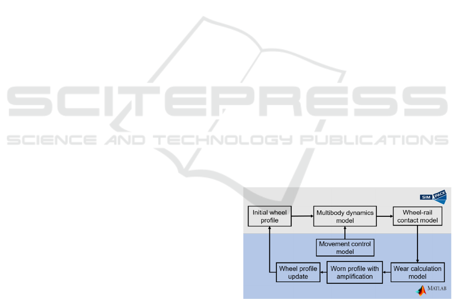
The overall framework is illustrated in Figure 1,
where arrows indicate the flow of output results
between submodel. Detailed descriptions of each
submodel are provided in the following sections.
Figure 1: Overall framework of proposed wear prediction
model based on co-simulation.
3.1 Multibody Dynamics Model of
Stacker Crane
The multibody dynamics model of a single-mast
stacker crane was developed using the multibody
simulation software Simpack (Yu & Fottner, 2024).
SIMULTECH 2025 - 15th International Conference on Simulation and Modeling Methodologies, Technologies and Applications
194
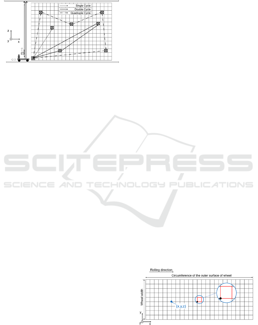
Figure 2 illustrates the model structure along with a
typical application scenario of stacker cranes.
Figure 2: Schematic representation of stacker crane and its
working scenario.
The model comprises a mast, a traverse, a lift
carriage, two running wheels, and a rail. The wheel-
rail system is modelled using Simpack’s built-in Rail
module. The initial wheel profile is rimless, while the
rail uses the standard UIC60 profile, commonly used
in railway applications. Key parameters for modelling
the stacker crane system, such as mast height, average
load capacity, operating velocity, and wheel diameter
and width, are detailed in the study (Yu & Fottner,
2024).
3.2 Movement Control Model
Since Simpack cannot model the complex
movements of a stacker crane, this paper integrates an
external movement control program developed by
Rücker et al. (Rücker et al., 2020) in
MATLAB/Simulink. The program determines the
rack positions required for movement within a single
work cycle based on the selected stacker crane
operation mode. It then computes the corresponding
acceleration, velocity, and displacement signals for
each time step. These signals are then transmitted to
the joint points of the multibody model via co-
simulation, thereby enabling precise control of the
stacker crane’s movements. Figure 2 shows three
typical operation modes of stacker cranes: single
cycle, double cycle, and quadruple cycle. In practice,
stacker cranes operate using a combination of these
modes to improve efficiency (Siciliano et al.).
However, for simplification, this study excludes such
combinations from the simulation.
3.3 Wheel-Rail Contact Model
The wheel-rail contact model is a critical component
of the wear prediction framework, as it defines the
contact area and normal force distribution within the
contact patch, significantly influencing wear results.
This paper uses Simpack’s Rail module for wheel-rail
contact calculations (Vollebregt et al., 2011). The
outputs from the contact model are transferred to the
discrete outer surface of the wheel in MATLAB,
where they are used for subsequent wear calculation
and profile updates.
3.3.1 Wheel-Rail Contact Calculation in
Simpack
Since the wheel and rail have quasi-identical material
properties, the wheel-rail contact can be treated as an
uncoupled normal and tangential contact problem that
is solved sequentially (Sichani, 2013). The normal
contact problem is addressed using Hertzian theory,
while the tangential contact problem is solved using
the FASTSIM algorithm based on Kalker’s simplified
theory. Results from the wheel-rail contact
calculations in Simpack—such as the lateral contact
point position and normal contact force—are used to
determine the position and size of the elliptical
contact area and the normal contact pressure within
that area.
3.3.2 Discretization of the Outer Surface of
Wheel
To further investigate wheel-rail contact and wear
behaviour, the outer surface of the wheel tread should
be discretized. This discretization divides the global
contact problem into discrete cells on the wheel
surface, enabling the local computation of worn
material within each cell of the contact area.
The wheels on stacker cranes are generally
rimless and can be approximated as cylindrical. When
the wheel is unfolded along its axis, the outer surface
can be represented as rectangular, where the length of
the rectangle corresponds to the wheel’s
circumference and the width represents the wheel
tread width. This rectangular surface is discretized
into a grid of 1×1 mm square cell, as shown in Figure
3. For illustrative purposes, the figure does not
represent the actual 1×1 mm cell size to scale.
Figure 3: Discretization of wheel outer surface.
A New Numerical Method for Fast Prediction of Wheel Tread Wear for Stacker Cranes
195
The three-dimensional coordinate information of
each grid node, as shown in Figure 3, is stored in a
MATLAB cell array. The 𝑥 and 𝑦 coordinates define
the node’s position on the wheel’s outer surface,
while the 𝑧 coordinate represents the wear depth at
that node. Each cell is referenced by its lower-left
node, which serves as the reference point for
subsequent contact area searches. As illustrated in
Figure 3, the representative node for the cell
highlighted in red is indicated by the black node at its
lower-left corner.
3.3.3 Search for Contact Area on Discrete
Wheel Surface
In this step, the wheel-rail contact area determined by
Simpack is mapped onto the corresponding discrete
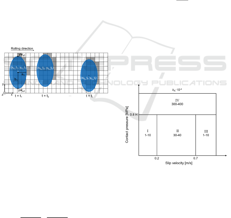
wheel surface in MATLAB. Figure 4 shows the
wheel-rail contact area at each time step during the
stacker crane’s movement. The blue elliptical region
represents the contact area calculated by Simpack,
while the grey cells depict the corresponding discrete
representation of the contact area on the wheel’s outer
surface.
Figure 4: Search for contact area at each time step 𝑡
.
As shown in Figure 4, the position and size of the
elliptical contact area are determined by the wheel’s
lateral contact positions 𝑦
,
and 𝑦
,
at the contact
point, as well as the semi-axis lengths 𝑎 and 𝑏 of the
elliptical contact area.
To discretize the elliptical contact area (blue region
in Figure 4) onto the grid, it is necessary to identify
which grid cells (grey region in Figure 4) lie within the
contact area. This paper uses the positional relationship
between a point and an ellipse, as defined in Equation
(1), where (𝑥
,𝑦
) represents the centre of the
elliptical contact area, (𝑥,𝑦) the lower-left node of a
cell. Specifically, the formula determines whether the
lower-left node of a cell lies inside or on the boundary
of the ellipse. If it does, the corresponding cell is
considered part of the contact area.
(
𝑥−𝑥
)
𝑎
+
(
𝑦−𝑦
)
𝑏
1
(1
)
3.4 Wear Calculation Model
This paper applies the Archard wear model to
calculate the volumetric worn material on the wheel.
The wear depth is then determined using the wear
distribution model developed in this study.
3.4.1 Archard Wear Model
In the Archard wear model, the volume of worn
material is directly proportional to the normal contact
force and the sliding distance, while inversely
proportional to the hardness of the softer material in
the wheel-rail pair. This relationship is expressed by
Equation (2),
𝑉
=𝑘⋅
𝐹
⋅𝑠
𝐻
(2
)
where 𝑉
is the worn volume, 𝑘 the wear
coefficient, 𝐹
the normal contact force, 𝐻 the
hardness of the softer material in the wheel-rail
material pair in MPa, and s the sliding distance. The
wear coefficient 𝑘 is a dimensionless factor that
depends on normal contact pressure and sliding
velocity, as shown in Figure 5 (Jendel, 2002). The
values of 𝑘 were experimentally determined under
dry and clean wheel-rail contact conditions. For
simplification, this paper uses the mean values of the
wear coefficients for different regions, i.e. 𝑘
=
𝑘
= 5×10
-4
, 𝑘
= 35×10
-4
, and 𝑘
= 350×10
-4
.
Figure 5: Archard wear chart (Jendel, 2002).
3.4.2 Wear Depth Distribution
According to Hertzian theory, normal contact
pressure follows a parabolic distribution across the
contact area. The maximum pressure 𝑃
occurs at
the centre of the contact area, as expressed in
SIMULTECH 2025 - 15th International Conference on Simulation and Modeling Methodologies, Technologies and Applications
196

Equation (3) (Mostofi & Gohar, 1980), and gradually
decreases toward the edges of the contact area.
𝑃
=
3
2
⋅
𝐹
𝐴
(3)
According on the Archard wear model, wear
volume is proportional to the normal contact force. As
a result, wear depth across the contact area is also
expected to follow a parabolic distribution (Heinrich
& Klüppel, 2008). Building on this assumption, we
developed a parabolic wear depth distribution model
based on the Euclidean distance between discrete
nodes and the centre of the contact area. The
Euclidean distance is calculated using Equation (4):
𝑑=
(
𝑥−𝑥
)
+
(
𝑦−𝑦
)
(4)
where 𝑥 and 𝑦 are the coordinates of any node
within the discretized contact area, 𝑥
and 𝑦
the
coordinates of the contact area centre, 𝑑 the
Euclidean distance between these two points. When
𝑑= 0, meaning the node is located at the centre of the
contact area, the wear depth reaches its maximum
value. Conversely, when 𝑑 reaches its maximum
value 𝑑
, indicating the node is at the edge of the
contact area, the wear depth becomes zero.
If the contact area is divided into cells of size
𝛥𝑥 × 𝛥𝑦, the wear depth 𝛥𝑧 can be expressed by
Equation (5), where 𝛥𝑠 represents the sliding
distance between two time-steps, and 𝑃(𝛥𝑥,𝛥𝑦) the
contact pressure within a cell.
∆z = 𝑘 ⋅
𝑃(𝛥𝑥,𝛥𝑦)⋅∆𝑠
𝐻
(5)
By combining Equation (2), (3) and (5), the wear
depth distribution 𝑧 in the contact area is given by
Equation (6):
𝑧=
3
2
⋅1−
𝑑
𝑑
/
⋅
𝑉
𝐴
(6)
3.5 Worn Profile Amplification and
Update
Wear is a slow and gradual process that develops over
long-term wheel-rail contact. The operational
lifespan of a stacker crane’s wheel can reach up to 10
8
rotations. However, simulating the complete wear
process over its entire lifecycle is impractical due to
the enormous computational resources and time
required. To address this, the wear results must be
magnified to effectively represent long-term wear
behaviour. The calculated wear depth is subtracted
from the initial wheel profile to model the changes in
the wheel profile due to wear. The updated wheel
profile is then used in subsequent simulation
iterations.
Chapter 2 reviews relevant research on
magnification of wear results. A common approach is
to linearly scale the wear results of a single simulation
iteration using a user-defined multiplier factor. For
example, if 10 simulated cycles correspond to 1,000
actual working cycles, a multiplier factor of 100 is
applied. While higher multiplier factors can
significantly reduce simulation time, they may also
lead to unrealistically concentrated wear distribution
within the contact area. Additionally, they can
generate excessively steep or discontinuous updated
wheel profiles, leading to instability in subsequent
numerical iterations.
When the stacker crane moves along a linear rail,
wheel lateral displacements vary due to movement-
induced excitation. These displacements shift the
contact position, subsequently altering the wear
position. According to the wear distribution model,
wear is concentrated at the centre of the wheel-rail
contact area, with intensity decreasing toward the
edges of the contact area. Based on this principle,
subsequent wear is assumed to accumulate in both
lateral and longitudinal directions along the initial
wear profile. Each accumulation includes a lateral
displacement 𝑦
at each node within the contact
area, while the wear depth at the original position is
simultaneously added onto the displacement position.
The lateral displacement 𝑦
follows a normal
distribution, as expressed in Equation (7):
𝑦
~𝑁(𝜇,𝜎)
(7)
where 𝜇 = 0, indicating that subsequent wear
accumulates at the centre of the initial wear area. The
value of 𝜎 determines the spread of the wear
distribution across the wheel surface, where a higher
𝜎 results in a more evenly distributed wear pattern
across the wheel tread. 𝑁 is the wear amplification
factor, representing the number of iterations in the
accumulated wear process described above. After
wear depth amplification, the wheel profile is updated
and used as the initial profile for the subsequent
dynamics simulation iterations.
4 MODEL VERIFICATION AND
RESULTS DISCUSSION
This section performs a verification of the proposed
model by comparing it with Simpack’s built-in wear
calculation model. While Simpack includes a built-in
wear calculation model, it does not account for the
A New Numerical Method for Fast Prediction of Wheel Tread Wear for Stacker Cranes
197
progressive expansion of the worn area over extended
simulation iterations, resulting in an overestimation
of wear accumulation (Bosso & Zampieri, 2019).
However, since experimental validation with real
measurements is planned for future work, the current
results should be regarded as a verification rather than
a comprehensive validation.
To evaluate the developed wear calculation
model, the unaccumulated result is compared with the
Simpack’s calculation result, which serves as the
baseline. The simulation parameters provided by (Yu
& Fottner, 2024) are used for comparison. The
simulated stacker crane has a height of 30 meters and
an average load capacity of 2,000 kg. The wheels,
made of 42CrMo4 steel material with a Poisson’s
ratio of 0.3, have a diameter of 500 mm. The wheel-
rail friction coefficient is 0.2. The simulation was
conducted for 100 work cycles using the double-cycle
operation mode.
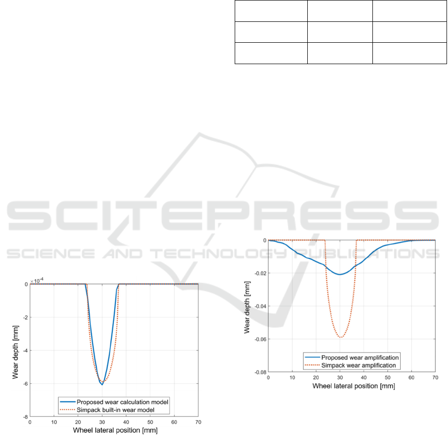
Figure 6 shows wheel wear depth at different
lateral positions for two simulation results. The red
dashed line represents the result obtained using
Simpack’s built-in Archard wear model, while the
blue solid line corresponds to the MATLAB-based
wear calculation model developed in this paper. As
shown in the figure, the maximum wear depth
calculated by the proposed wear model is slightly
higher than that calculated with the Simpack model.
Additionally, the wear distribution predicted by the
proposed method shows a minor shift away from the
centre of the contact area compared to the Simpack
result.
Figure 6: Comparison between the proposed wear model
and Simpack built-in wear model.
Table 1 compares the maximum wear depth and
its corresponding lateral position. The results indicate
that the wear calculation model developed in this
paper is highly consistent with Simpack’s built-in
model results. This consistency emphasises the
reliability of the proposed MATLAB-based wear
calculation model, establishing it as a robust
foundation for subsequent wear amplification and
wheel profile updates.
Table 1: Comparison of two wear calculation models for the
maximum wear depth and the lateral position it occurs.
Proposed wear
model
Simpack’s built-
in wea
r
model
Maximum wear
de
p
th
/
10
-4
mm
6.08 5.89
Wheel lateral
p
osition
/
mm
30.00 30.55
To verify the developed wear amplification
method, an amplification factor of 𝑁 = 100 is
selected. Similarly, a distance factor of 100 is applied
in the Simpack wear model to enable a direct
comparison with the wear amplification approach
proposed in this study. The results, shown in Figure
7, compare the two methods. The red dashed line
represents the Simpack result, while the blue solid
line corresponds to the result from the wear
amplification developed in this paper. The results
indicate that the amplified wear depth calculated in
Simpack is significantly higher than that obtained
using the proposed method. Additionally, the wear
area predicted by Simpack is narrower.
Figure 7: Comparison of wear amplification results with a
factor of 100 for one simulation iteration.
The significant differences arise from the
fundamentally different methods of wear
superposition. In Simpack, the distance factor directly
amplifies the results of a single simulation run,
keeping the wear zone consistent with the initial wear
profile. Consequently, subsequent wear is
proportionally amplified along the same profile. In
contrast, the amplification method proposed in this
SIMULTECH 2025 - 15th International Conference on Simulation and Modeling Methodologies, Technologies and Applications
198
paper accounts for the lateral expansion of the wear
profile as wear accumulates over time. This approach
considers the dynamic redistribution of wear,
providing a more refined representation of the wear
process over multiple iterations.
At this stage, the impact of the worn profile
update on simulation results is analysed. To simulate
the long-term work cycles of a stacker crane within a
finite number of simulation runs, a wear amplification
factor of 𝑁 = 100 is applied, with the profile updated
every hundred simulated work cycles. Each profile
update represents one simulation iteration, equivalent
to 10,000 actual work cycles of stacker cranes. In this
simulation, fifteen wear iterations are performed to
analyse the wear behaviour under profile updates,
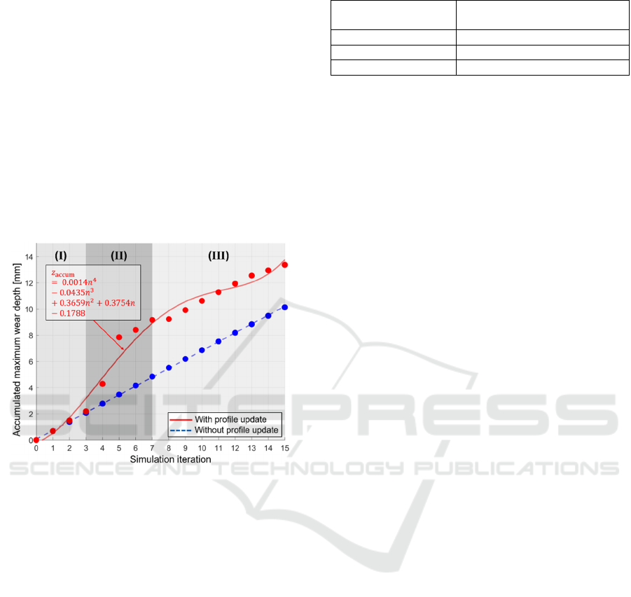
with the results presented in Figure 8.
Figure 8: Comparison of results with/without worn profile
update regarding multiple simulation iterations.
The blue dashed line shows that wear behaviour
without profile updates follows a quasi-linear trend
throughout the iteration process. In contrast, when
profile updates are considered, the wheel wear
process demonstrates three distinct wear regimes as
work cycles increase, as shown by the red solid curve.
These regimes can be categorized as early stable wear
(I), mid-rapid wear (II), and late stable wear (III).
The red curve in Figure 8 represents a fourth-
degree polynomial fit to the red discrete points. The
fitting result is expressed by the equation next to the
red line in Figure 8, where 𝑧
is the accumulated
maximum wear depth on the wheel tread in mm, 𝑛
the number of simulation iterations, each
corresponding to 10,000 actual work cycles of stacker
cranes.
To quantitatively analyse wheel wear behaviour,
the wear rate is determined at different work cycle
stages. It represents the average maximum wear depth
per 10,000 actual work cycles at each stage. The
summarized results are shown in Table 2.
Table 2: Wheel wear rate under different work cycles.
Number of actual
wor
k
cycles
Predicted wear rate/ (mm/10
4
wor
k
cycles)
0
–
30,000 0.73
30,000
–
70,000 2.8
> 70,000 0.56
During the initial operation stage (work cycles
less than 30,000), wear has just begun and has
minimal impact on the wheel profile. In the middle
operation stage (work cycles between 30,000 and
70,000), wear may alter the wheel profile, leading to
a mismatch between the wear and rail profiles. This
mismatch reduces the contact area, accelerating
wheel wear. In the later operation stage (work cycles
more than 70,000), the wheel-rail profiles form a
better match, reducing the wheel wear rate.
5 CONCLUSION AND OUTLOOK
This paper presents a numerical investigation into the
wheel wear prediction for stacker cranes. A co-
simulation framework is developed by integrating the
Simpack multibody model with a MATLAB-based
wear calculation model. Additionally, a wear
amplification approach is introduced to simulate the
lifecycle of a stacker crane’s wheel within a feasible
number of simulation iterations. Instead of applying a
simple linear multiplier to the wear results, the
proposed approach accounts for the wear
amplification along the traverse contact position,
providing a more refined estimation of long-term
wear progression. The developed wear calculation
model is compared with Simpack’s built-in wear
model. Results indicate that the proposed approach
produces a similar wear depth distribution to
Simpack’s model, while significant differences are
observed when applying a wear amplification factor
of 100. This discrepancy occurs because the wear
accumulation method proposed in this paper
considers the lateral expansion of the contact area due
to wear.
This paper also investigates the influence of worn
profile changes on wheel wear behaviour across
different operation stages. It is found that the wheel
wore slowly first, then wore rapidly and finally
slowed again. The proposed calculation method
enables a quantitative prediction of stacker crane
wheel wear at various work cycle stages, providing
specific research significance and practical value for
the maintenance planning of stacker cranes.
Future research will focus on experimental
validation of the proposed method to further ensure
A New Numerical Method for Fast Prediction of Wheel Tread Wear for Stacker Cranes
199

its reliability and accuracy. Real-world wheel wear
data from stacker cranes will be used to assess the
consistency between simulated and observed wear
behaviour. These experiments are excepted to provide
valuable insights for validating the proposed wear
amplification method, thereby enhancing its practical
applicability in industrial fields.
ACKNOWLEDGEMENTS
The research has been conducted within the
industrielle Gemeinschaftsforschung [collective
industrial research] (IGF) project “VerStaRad:
Verschleißverhalten von Stahllaufrädern an
Regalbediengeräten” (IGF project number 23053)
basis of a decision of the German Bundestag [Federal
Parliament].
REFERENCES
Achouch, M., Dimitrova, M., Ziane, K., Sattarpanah
Karganroudi, S., Dhouib, R., Ibrahim, H., & Adda, M.
(2022). On Predictive Maintenance in Industry 4.0:
Overview, Models, and Challenges. Applied Sciences,
12(16). https://doi.org/10.3390/app12168081
Bosso, N., & Zampieri, N. (2019). Numerical stability of
co-simulation approaches to evaluate wheel profile
evolution due to wear. International Journal of Rail
Transportation, 8(2), 159–179. https://doi.org/10.1080/
23248378.2019.1672588
Braghin, F., Lewis, R., Dwyer-Joyce, R., & Bruni, S.
(2006). A mathematical model to predict railway wheel
profile evolution due to wear. Wear, 261(11-12), 1253–
1264. https://doi.org/10.1016/j.wear.2006.03.025
Große, K., Sartorius, J., & Fittinghoff, M. (2018).
Predictive Maintenance at Automatic Storage Retrieval
Machines (ASRS) with Vibration Sensors. Logistics
Journal. Advance online publication. https://doi.org/
10.2195/LJ_NOTREV_GROSSE_EN_201812_01
Heinrich, G., & Klüppel, M. (2008). Rubber friction, tread
deformation and tire traction. Wear, 265(7-8), 1052–
1060. https://doi.org/10.1016/j.wear.2008.02.016
Iwnicki, S., Nielsen, J. C. O., & Tao, G. (2023). Out-of-
round railway wheels and polygonisation. Vehicle
System Dynamics, 61(7), 1787–1830. https://doi.org/
10.1080/00423114.2023.2194544
Jendel, T. (2002). Prediction of wheel profile wear—
comparisons with field measurements. Wear, 253(1–2),
89–99.
Laile, M. M., & Fottner, J. (2021). Computing a Realistic
Load Collective for the Rail-wheel Contact of Stacker
Cranes. In 2021 The 8th International Conference on
Industrial Engineering and Applications(Europe) (pp.
46–50). ACM. https://doi.org/10.1145/3463858.346
3862
Mostofi, A., & Gohar, R. (1980). Pressure distribution
between closely contacting surfaces. Journal of
Mechanical Engineering, 22(5), 251–259.
Rücker, A., Rief, J., & Fottner, J. (2020). An investigation
of mean energy demand, performance and reference
cycles for stacker cranes. FME Transactions, 48(2),
307–312. https://doi.org/10.5937/fme2002307R
Sichani, M. (2013). Wheel-Rail Contact Modelling in
Vehicle Dynamics Simulation [Disseration]. KTH
Royal Institute of Technology, Stockholm,Sweden.
Siciliano, G., Durek-Linn, A., & Fottner, J. Optimization of
the Bottleneck Caused by Stacker Cranes in Dynamic
Hybrid Pallet Warehouses and Investigation of the
Influence of the Input/Output Area on Performance. In
12th International Conference on Simulation and
Modeling Methodologies, Technologies and
Applications (SIMULTECH 2022) (pp. 123–130).
https://doi.org/10.5220/0011313600003274
Tunna, J., Sinclair, J., & Perez, J. (2007). A Review of
wheel wear and rolling contact fatigue. Proceedings of
the Institution of Mechanical Engineers Part F Journal
of Rail and Rapid Transit, 221
(2), 271–289.
https://doi.org/10.1243/0954409JRRT72
Vollebregt, E. A., Weidemann, C., & Kienberger, A. (Eds.)
(2011). Use of "CONTACT" in multi-body vehicle
dynamics and profile wear simulation: initial results.
Yang, Y., Ling, L., Wang, J., & Zhai, W. (2023). A
numerical study on tread wear and fatigue damage of
railway wheels subjected to anti-slip control. Friction,
11(8), 1470–1492. https://doi.org/10.1007/s40544-022-
0684-8
Yu, M., & Fottner, J. (Eds.) (2024). Entwicklung und
Validierung einer praxisgerechten Methode zur
Verschleißberechnung im Rad-Schiene-System von
Regalbediengeräten (German). Logistics Journal.
Zhang, J., Xu, B., & Guan, X. (2013). A combined
simulation procedure for wear assessment of the HXN5
locomotive. Wear, 314(1-2), 305–313. https://doi.org/
10.1016/j.wear.2013.11.042
SIMULTECH 2025 - 15th International Conference on Simulation and Modeling Methodologies, Technologies and Applications
200
