
Transformation of Cyclic Process Models with Inclusive Gateways to Be
Executable on State-of-the-Art Engines
Thomas M. Prinz
1 a
, N. Long Ha
2 b
and Yongsun Choi
3 c
1
Course Evaluation Service, Friedrich Schiller University Jena, Jena, Germany
2
Faculty of Economic Information Systems, University of Economics, Hue University, Vietnam
3
Department of Industrial and Management Engineering, Inje University, South Korea
Keywords:
Inclusive Semantics, OR-joins, Loops, Transformation, Loop Decomposition.
Abstract:
One aim of business process management is to automate business process models. Since process models
shall reflect occurring processes in companies, such models can be complex and contain non-trivial behavior
with inclusive semantics and loops formed by sequence flows. This paper shows on a test set that state-of-
the-art BPMN execution engines do not fully support inclusive gateways, especially, if they are within loops.
This circumstance prevents the one-to-one automation of process models. As there is no transformation of
process models with inclusive semantics into models without them not risking the exponential growth of the
models, this paper presents a transformation that decomposes cyclic process models into a set of message-
exchanging acyclic process models. The transformed models are directly executable on most investigated
engines. The transformation itself is achievable in quadratic time complexity, increases the size of the model
just quadratically in the worst case, and, finally, can be fully automated as pre-processing step before execution,
thus avoiding to change execution engines.
1 INTRODUCTION
One of the main objectives of Business Process Man-
agement (BPM) comprises the identification and for-
malization of business processes. Business process
models describe how and in which order different
tasks are performed to finally reach business goals
(Dumas et al., 2013). These process models orient
on actual processes occurring in businesses. For this
reason, some process models can become complex
and contain cyclic and non-trivial structures. How-
ever, such complex structures increase the difficulty
of analysis and automation (Prinz et al., 2022).
The Business Process Model and Notation
(BPMN) (Object Management Group (OMG), 2011)
is a standard to describe business process models. Al-
though BPMN covers special loop tasks for repeat-
ing a task or sub-process, one can model loops with
sequence flows (edges) creating non-trivial strongly-
connected components in the process model. Such
loops in process models are called sequence flow
a
https://orcid.org/0000-0001-9602-3482
b
https://orcid.org/0000-0002-5673-2812
c
https://orcid.org/0000-0002-8605-4055
loops in the following. Gateways offer the possibil-
ity to split (diverge) and to join (converge) sequence
flows. Traditional and well-supported gateways are
exclusive and parallel gateways. When using exclu-
sive gateways, exactly one of the outgoing edge is fol-
lowed by a token and exactly one such token is ex-
pected to arrive at exactly one of the incoming edges.
In parallel gateways, all outgoing edges get tokens in
such that they provide concurrency; and on all incom-
ing edges it is expected that tokens arrive — a syn-
chronization of concurrency. Inclusive gateways are
an in-between of exclusive and parallel gateways. Di-
verging inclusive gateways (OR-splits) should place
at least one token on one outgoing edge, however, it
is possible to add tokens to an arbitrary subset of the
outgoing edges and, thus, create concurrency. Con-
verging inclusive gateways (OR-joins) can accept a
token on a single incoming edge or on a subset of their
incoming edges.
Inclusive gateways are supported by many model-
ing languages such as BPMN and Event-driven Pro-
cess Chains (Keller et al., 1992) (EPC), however,
the semantics of OR-joins is disputed in research
and practice (Kindler, 2006; Dumas et al., 2007;
Mendling and van der Aalst, 2007; Mendling et al.,
280
Prinz, T. M., Ha, N. L. and Choi, Y.
Transformation of Cyclic Process Models with Inclusive Gateways to Be Executable on State-of-the-Art Engines.
DOI: 10.5220/0013386400003929
In Proceedings of the 27th International Conference on Enterprise Information Systems (ICEIS 2025) - Volume 2, pages 280-291
ISBN: 978-989-758-749-8; ISSN: 2184-4992
Copyright © 2025 by Paper published under CC license (CC BY-NC-ND 4.0)

2008; Börger et al., 2009; Völzer, 2010; Christiansen
et al., 2010; Prinz and Amme, 2015; Corradini et al.,
2022; Prinz et al., 2022). Their semantics is accepted
in the case of acyclic process models (i. e, without se-
quence flow loops) for most standards: An OR-join is
waiting as long as any token may reach one of its in-
coming edges (Völzer, 2010). In cyclic process mod-
els, however, such a behavior may result in some OR-
joins waiting mutually for each other — so-called vi-
cious circles (Kindler, 2006).
Although standards allow for using OR-joins, they
are less technically supported in execution engines.
(Corradini et al., 2022) unveiled that popular BPMN
engines do not fully support the BPMN semantics
of OR-joins, especially, in the case of sequence flow
loops. However, as explained before, some derived
business process models may contain OR-joins and
such loops. For example, Figure 1 shows a BPMN
process model, which cannot be executed success-
fully with current execution engines (such as Ca-
munda (Camunda Services GmbH, 2024b), bpmn.io
(Camunda Services GmbH, 2024a), and Activiti (Al-
fresco, 2024)) although it is sound (Prinz and Amme,
2015). The engines either do not execute it at all be-
cause of unsupported elements (OR-splits and OR-
joins), blocking at first both diamonds O
1
and O
2
with circles (OR-joins), or cause unexpected behavior
(i. e., lacks of synchronization (Sadiq and Orlowska,
2000)). Currently, there is no transformation of OR-
joins into exclusive and parallel gateways without the
risk of an exponential increase in the size of the pro-
cess model in some cases (Favre et al., 2015). Actu-
ally, there are some promising semantics of OR-joins,
which can execute them in situations such as in Fig. 1
(e. g., (Prinz and Amme, 2015)); however, as usual, it
will take its time until they are widely accepted and
supported in engines. At this time, there is no ap-
proach to execute sound BPMN process models with
inclusive gateways and sequence flow loops on state-
of-the-art engines in all cases!
This paper presents an approach transforming
BPMN process models with inclusive gateways and
sequence flow loops into message-/signal-exchanging
process models without loops by applying the
methodology of loop decomposition (Prinz et al.,
2022; Prinz et al., 2025). This transformation is
achievable in quadratic time and (in the very seldom
worst-case) with a quadratic increase in the size of
the process model. We will show in an evaluation
that the transformed models are directly executable
on current execution engines, which support inclu-
sive gateways in acyclic process models, message or
signal exchanges, and event-based gateways. The
only restriction of the approach is that the original
process model should be sound since, otherwise, it
is not guaranteed that the transformed process mod-
els have the same behavior as the original model.
Of course, it is disputed in research how to define
soundness (i. e., the absence of deadlocks and lacks
of synchronization (Sadiq and Orlowska, 2000)) in
the case of inclusive semantics. Theoretically, our
work is based on the semantics and concepts of pre-
vious work (Prinz and Amme, 2015). Practically,
we expect that almost all practitioners want to avoid
deadlocks and lacks of synchronization during the ex-
ecution of their process models although this may
would differ in some rare cases of the defined behav-
ior by the BPMN 2.0.2 specification (Object Manage-
ment Group (OMG), 2011). The semantics proposed
in (Prinz and Amme, 2015) is proved to execute all
process models with OR-joins without deadlocks and
lacks of synchronization if this is possible. After the
transformation suggested in this paper, even the inclu-
sive semantics of the BPMN 1.2 specification can be
applied.
In the context of this paper, we assume normal-
ized process models (Favre et al., 2015) (e. g., without
gateways both converging and diverging) for simpli-
fication but the approach is also applicable without
normalization. For illustration of the transformation,
we apply it on a BPMN process model although we
describe the transformation more formally in the de-
scription.
To explain the approach, Section 2 introduces
some basics to understand this work. Subsequently,
this paper motivates the problem of state-of-the-
art engines in Sect. 3. Section 4 provides a de-
tailed description on how to transform process models
with loops into message-exchanging models without
loops. This transformation is evaluated and discussed
in Sect. 5. Finally, Section 6 concludes the paper.
2 PRELIMINARIES
Process modeling languages for industry (e. g.,
BPMN (Object Management Group (OMG), 2011))
include a wide range of symbols, types of nodes, and
other process artifacts to address diverse situations
encountered in practical scenarios. Workflow graphs
(Sadiq and Orlowska, 2000) (besides workflow nets
(van der Aalst, 1997)) concentrate on the main con-
trol flow of such industrial modeling languages. By
reducing the number of central control flow elements,
workflow graphs provide a simplified representation
of process models for research. The following defini-
tion of workflow graphs extends usual definitions by
signals that can be thrown and caught:
Transformation of Cyclic Process Models with Inclusive Gateways to Be Executable on State-of-the-Art Engines
281

B
A
O
1
X
2
X
1
i
1
i
2
O
2
E
D
F
G
C
H I
o
1
o
2
Figure 1: A BPMN process model with inclusive gateways within a sequence flow loop.
Definition 1 (Workflow Graph). A workflow graph
N, E, λ, Λ, τ, γ, M refers to a digraph N, E . N is a
set of nodes and E N N is a set of edges con-
necting nodes. For an edge s, t e E, s is called
the source and t is called the target of e. A node
n has incoming edges, n s, n E , and out-
going edges, n n, t E . Λ is a set of labels
Start, Task, AND, OR, XOR, End and λ: N Λ is a
total mapping that assigns a label to each node. An
assigned label defines various properties to n:
• Nodes with label Start (the start nodes) have no
incoming but exactly one outgoing edge. Nodes
with label End (the end nodes) have exactly one
incoming but no outgoing edge. There is at least
one Start and one End node, and each node lies on
a path from a Start to an End node.
• Nodes with label Task (tasks) have exactly one in-
coming and one outgoing edge. These nodes indi-
cate the specific work to be accomplished.
• All other nodes have labels AND, OR, or XOR.
They are separated into split and join nodes. Split
nodes (i. e., AND-, OR-, and XOR-split) have ex-
actly one incoming ( n 1) and at least two
outgoing edges ( n 2). Join nodes (i. e.,
AND-, OR-, and XOR-join) have at least two in-
coming edges ( n 2) and exactly one outgo-
ing edge ( n 1).
Extending the usual definition of workflow graphs, M
is a finite set of signals and τ: N M and γ: N M
are partial mappings assigning signals to some nodes.
τ describes thrown and γ describes caught signals.
Signals are specific for tasks, start, and end nodes,
and such nodes can either throw or catch a signal but
not both.
Figure 1 also serves as an illustration of a work-
flow graph and shows the different kinds of nodes.
The paper borrows notions from BPMN to visualize
different types of nodes: Thin circles are used for start
nodes, while thick circles indicate end nodes. Tasks
are depicted as rounded rectangles, while diamonds
represent splits and joins. A cross in the diamond
marks XOR-splits and XOR-joins, a plus sign in the
Figure 2: Throwing and catching (start and end) nodes and
a signal-based (event-based) XOR-split.
diamond marks AND-splits and AND-joins, and a cir-
cle in the diamond marks OR-splits and OR-joins.
Nodes that throw or catch signals are later de-
picted as double-lined circles with an envelope in-
side and the name of the signals is written close to
them. Thrown signals are identified by filled en-
velopes whereas caught signals are identified by un-
filled envelopes. Start and end nodes with signals do
not have double-lines. XOR-splits whose succeed-
ing nodes all catch signals are signal-based (called
“event-based” in BPMN): That outgoing edge is fol-
lowed by the control-flow whose target caught a sig-
nal first. Thus, they behave like XOR-splits locally
but may have specific behavior interacting with other
workflow graphs. To identify signal-based XOR-
splits faster, the diamond contains a pentagon sur-
rounded with two thin circles as in BPMN. Figure 2
illustrates nodes throwing and catching signals.
If a node has a path to itself, the workflow graph
contains a loop:
Definition 2 (Loops, Entries, Exits, and Do-Bodies).
A loop L N
L
, E
L
of a workflow graph W FG is a
non-trivial strongly connected component, in which
every node has a path to each other (Cormen et al.,
2009).
A node en of L is a loop entry if en has at least one
incoming edge in (a loop-entry edge) that is not in E
L
.
Similarly, a node ex of L is a loop exit if ex has at least
one outgoing edge out (a loop-exit edge) that is not in
E
L
.
The do-body of L is that subgraph, which is be-
tween L’s entries and L’s exits (without visiting any
exit) (Prinz et al., 2025).
A workflow graph can be categorized as either
cyclic or acyclic. A cyclic workflow graph contains at
ICEIS 2025 - 27th International Conference on Enterprise Information Systems
282

least one loop, while an acyclic workflow graph has
no loops. The loop in the workflow graph of Fig. 1
comprises all nodes and edges in the subgraph be-
tween O
1
, O
2
, X
1
, and X
2
. The loop entries are O
1
and
O
2
and the loop exits are X
1
and X
2
. The do-body for
this example contains all nodes and edges of the loop
except X
1
and X
2
and their incoming and outgoing
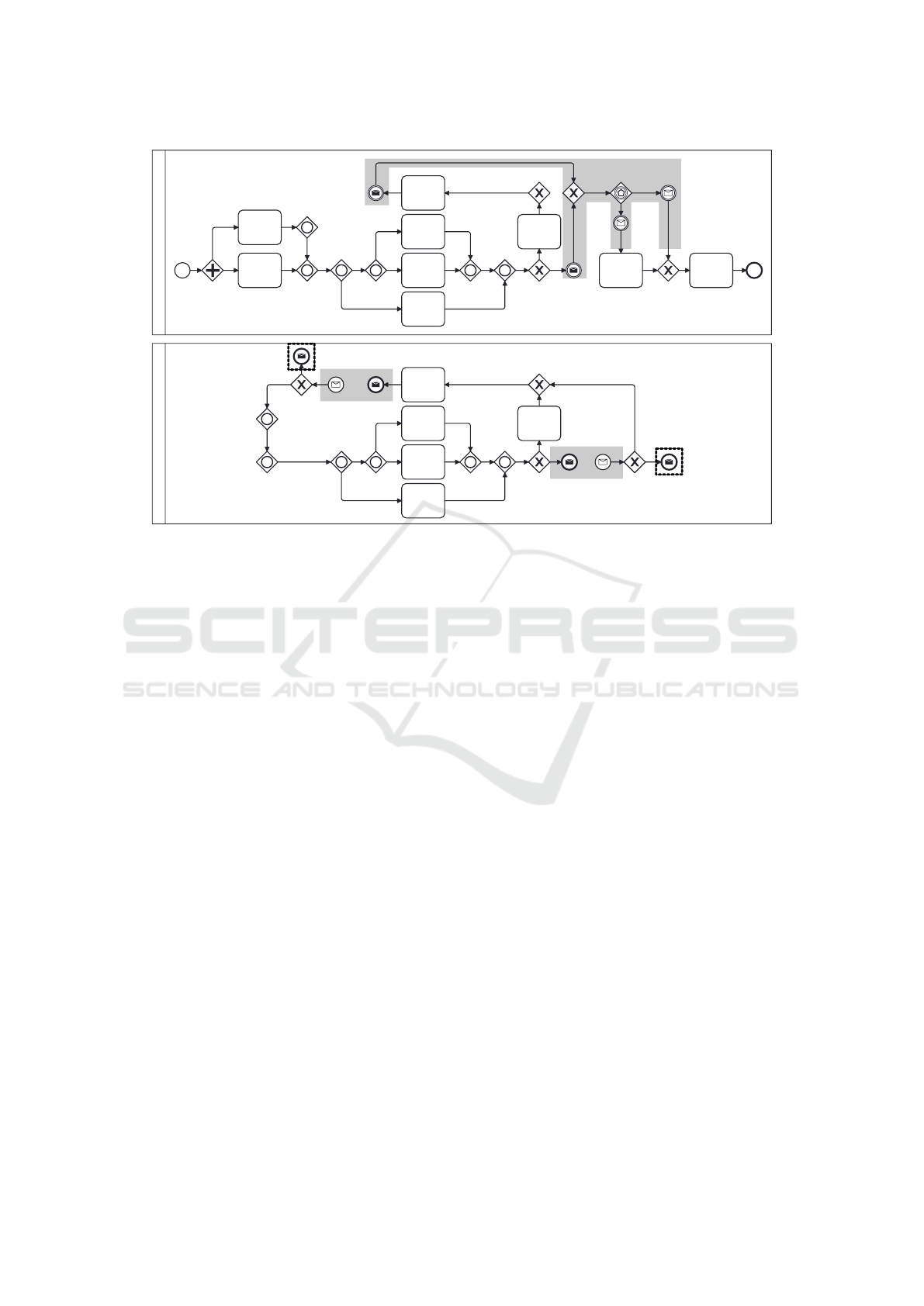
edges. Figure 3 illustrate the loop (gray rectangle),
its entries (dashed squares), its exits (solid squares),
and its do-body (dashed surrounded area).
The semantics of cyclic workflow graphs with
OR-joins is complex (Völzer, 2010). The reason is
that situations can arise where two OR-joins mutu-
ally wait for each other (Kindler, 2006; Völzer, 2010).
In this paper, we use the semantics of our previous
work (Prinz and Amme, 2015) that is complete for
sound workflow graphs. However, we emphasize that
an additional OR-join semantics for cyclic workflow
graphs is not needed after transformation. Therefore,
it is only used here for the sake of completeness.
We use a token game semantics describing
state transitions in a workflow graph WFG N,
E, λ, Λ, τ, γ, M . A state S of WFG is a total mapping
from the set of edges E to the set of natural numbers,
S : E N
0
. It describes the number of tokens on
each edge, e. g., S e 1 means that edge e in state
S carries 1 token. An initial state of WFG is a state
in which only one outgoing edge of exactly one start
node has a token.
A node n of WFG is waiting in a state S if at least
one incoming edge of n has a token. If n is neither an
AND-join nor an OR-join, n is enabled if it is waiting
in S. If n is an AND-join and all incoming edges of n
carry a token in S, n is enabled in S. If n is an OR-join,
then it has a waiting area ω n that contains all edges
where n must wait for their tokens (for more details,
we refer to (Prinz and Amme, 2015)). An OR-join n is
enabled in S, if it is waiting in S and no token is in n’s
waiting area except on n’s incoming edges. If there is
an enabled node n in S, then S can change into a state
S by executing n, written S
n
S . The resulting state
S is based on S with the following modifications: (1)
Each incoming edge in of n with at least one token
loses a token in S , except if n is an XOR-join, then
only one incoming edge loses a token. (2) The num-
ber of tokens on n’s outgoing edges depends on n’s
label. If n is an OR-split, then a non-empty set of out-
going edges of n gets an extra token in S . If n is an
XOR-split, then exactly one outgoing edge of n gets
an extra token in S . Otherwise, each outgoing edge
of n gets an extra token in S .
Signals delay or continue the execution of work-
flow graphs. The reader can assume a signal bus,
where catching nodes are registered to and are noti-
fied in the case of a signal with the right type. A start
node s N catching signal σ M, (γ s σ), means
that the workflow graph is instantiated in the initial
state when the signal σ is thrown to the bus. A node
n N, which catches σ (γ n σ) and is enabled in S,
will wait until σ is thrown to the bus. A node throw-
ing signal σ sends this signal to the bus when it is
executed or, in the case of an end node, when it has a
token on its incoming edge. Although they can also be
used within the original workflow graphs, for the sake
of simplicity with regard to reachability and sound-
ness as defined in the following, we use signals only
after the transformation.
The execution of a workflow graph starts with an
initial state, and is executed node by node, result-
ing in a chain of node executions and state transi-
tions. A state S is directly reachable from a state
S, depicted S S , if there is a possible state tran-
sition S
n
S , i. e., node n N is executed in state S.
S is reachable from a state S, depicted S S , if
there is a sequence/chain of directly reachable states
S
1
S
2
. . . S
k
, k 1, with S
1
S and S
k
S .
Two types of structural conflicts can occur in
workflow graphs, namely deadlocks and lacks of syn-
chronization. A deadlock arises from an initial state
when an AND-join or OR-join is waiting in a reach-
able state S, but is never enabled in reachable states
from S. A lack of synchronization results from an ini-
tial state when an edge carries more than one token
in a reachable state. A workflow graph is said to be
sound if it has neither a deadlock nor a lack of syn-
chronization (Fahland et al., 2011). In previous work,
we showed that no other semantics allows running
more workflow graphs sound than the one used here
(Prinz and Amme, 2015). In the context of the present
work, we assume that each XOR- and OR-split inde-
pendently decides after their execution which outgo-
ing edges receive an additional token.
3 INVESTIGATED EXECUTION
ENGINES
There are several tools and information systems that
support the modeling, simulation, and execution of
BPMN process models. As explained in the intro-
duction, few tools support OR-joins in loops without
leading to unexpected (unsound (van der Aalst et al.,
2011)) behavior. Such behavior usually results from
vicious circle situations (Kindler, 2006) leading either
to deadlocks or lacks of synchronization.
We have investigated 9 state-of-the-art systems
for executing or simulating BPMN process models.
The systems comprises Camunda (Camunda Services
Transformation of Cyclic Process Models with Inclusive Gateways to Be Executable on State-of-the-Art Engines
283

B
A
E
D
F
G
C
H I
O
1
X
2
X
1
i
1
o
1
i
2
o
2
O
2
Figure 3: The loop (gray rectangle) of Fig. 1, its entries O
1
and O
2
(dashed squares), its exits X
1
and X
2
(solid squares), and
its do-body (dashed surrounded area).
GmbH, 2024b), bpmn.io (Camunda Services GmbH,
2024a), Bizagi (bizagi, 2024), bpmn-simulator (All-
weyer and Schweitzer, 2024), Signavio (SAP Sig-
navio, 2024), Activiti (Alfresco, 2024), jBPM (KIE,
2024), Flowable (Flowable AG, 2024), and Bonita
Platform (Bonitasoft, 2024). They were checked to
determine if and how they support inclusive gateways
inside and outside of loops. For this check, we created
a small but efficient test set comprising four test cases.
Figure 4 shows the first test case with inclusive gate-
ways outside a loop. It checks if inclusive gateways
are supported at all. Figure 5 shows the second test
case with a structured vicious circle situation men-
tioned by (Völzer, 2010). It tests whether the engine
is able to execute OR-joins in a block-oriented loop
structure, or not. The third test case is illustrated in
Fig. 6: An example mentioned by (Prinz and Amme,
2015), for which there is a sound execution order, but
most OR-join semantics fail. The fourth and last test
case comprises our running example of Fig. 1. It is a
combination of test cases 2 and 3.
Table 1 summarizes the results of our experiments
for each of the investigated engines. A positive result
is that nowadays, most of the engines support inclu-
sive gateways. Signavio is an exception, which states
that OR-joins are unsupported for simulation. Ac-
tually, only 5 of 9 engines are able to execute case
2 with block-oriented structures correctly (i. e., only
5 seem to implement a BPMN 2.0.2-like semantics).
However, none of the engines supports cases 3 and 4.
They usually run into a deadlock since the OR-joins
are waiting mutually on each other. Otherwise, there
are situations, in which the wrong OR-join executes
first such that concurrent tokens are not synchronized.
Our investigations support our expectations. How-
ever, the tools are promising to support the process
models after the transformation proposed in this pa-
per.
4 TRANSFORMATION
Section 3 have unveiled drawbacks of state-of-the-
art execution engines regarding the semantics of OR-
joins, which is supported by observations of (Corra-
dini et al., 2018; Corradini et al., 2022). There are
several proposals for semantics of converging inclu-
sive gateways in research, such as (Prinz and Amme,
2015), (Corradini et al., 2022), and (Fahland and
Völzer, 2018). However, until one of them becomes
widely accepted and part of the BPMN standard or en-
gines, it will take some time. For this reason, the fol-
lowing three steps explain how to transform a (sound)
cyclic workflow graph with inclusive semantics so
that it can be executed on most modern execution en-
gines. This transformation is based on the method of
loop decomposition, which separates a cyclic work-
flow graph into a set of acyclic workflow graphs and is
explained and proved in detail in (Prinz et al., 2025).
The resulting set of acyclic workflow graphs repre-
sent the same behavior of the original process model
if that is sound. The third here presented step extends
those resulting acyclic workflow graphs after loop de-
composition with signals so that they can be directly
executed or simulated. In doing this, we present the
more formal extensions on an example in BPMN.
4.1 Identifying Loops and Their
Entries, Exits, and Do-Bodies
The first step to transform a given workflow graph
with OR-joins and loops is to identify all loops and
to check whether an OR-join is included in a loop, or
not. The identification of a loop can be achieved in
linear time complexity by (Tarjan, 1972). Figure 3
illustrates the loop included in the example BPMN
process model of Fig. 1 with a gray border. In the
following, we assume that we have identified at least
one OR-join within a loop. The loop in Fig. 3 contains
ICEIS 2025 - 27th International Conference on Enterprise Information Systems
284

B
A
C
Figure 4: Test Case 1: Inclusive gate-
way support.
B
A
C
D
Figure 5: Test Case 2: OR-joins in
structured loops.
B
A
D
C
Figure 6: Test Case 3: OR-joins in un-
structured loops.
Table 1: Investigated engines and their support of inclusive gateways.
Engine Case 1 Case 2 Case 3 Case 4 Comment
Camunda ✓ ✓ Deadlock for cases 3 and 4.
bpmn.io ✓ Deadlock for cases 2–4.
Bizagi ✓ Deadlock for cases 2–4.
bpmn-simulator ✓ ✓ Lack of synch. for cases 3 and 4.
Signavio Inclusive gateways not supported.
Activiti ✓ ✓ Deadlock for cases 3 and 4.
jBPM ✓ ✓ Deadlock for cases 3 and 4.
Flowable ✓ Deadlock for cases 2–4.
Bonita Platform ✓ ✓ Deadlock for cases 3 and 4.
four OR-joins.
Identifying loop entries and exits by Def. 2 can
be simply achieved by checking each gateway in the
loop if it has an incoming edge from outside of the
loop (entries) or an outgoing edge to outside the loop
(exits). The loop in Fig. 3 contains two loop entries
O
1
and O
2
(surrounded with a black dashed rectangle)
and two loop exits X
1
and X
2
(surrounded with a black
solid rectangle).
Loops can occur in many variants. Some loops
(such as the loop in Fig. 3) have nodes between their
entries and exits (of course, without passing a loop
exit). This area is the do-body of a loop as defined in
Def. 2. The do-body serves as a “converging area”
if there is any concurrency of tokens. In previous
work (Prinz et al., 2022; Prinz et al., 2025), we have
shown for sound workflow graphs that after the do-
body, when the first loop exit is reached by a token,
the area before, the area after, and the entire loop are
free of tokens except this one at the loop exit. Oth-
erwise, the workflow graph is unsound (Prinz et al.,
2025).
Identifying do-bodies can be achieved with a
depth-first search starting from each loop entry and
stopping locally at incoming edges of loop exits.
Thus, loop exits and their incoming and outgoing
edges are not included in the do-body. Note that the
do-body is not necessarily to be connected. It can
even be nearly empty. This is not important for the
next steps. Figure 3 illustrates the identified do-body
between the loop entries and loop exits as a dashed
black border. It covers most parts of the loop.
4.2 Copying the Loop into a New Pool
and Eliminating the Loop
The actual transformation of the model starts within
this current step. It copies the entire loop into a
new workflow graph, which we will illustrate as a
new BPMN pool in Figure 8 called “Loop Process
Model”. Note that the original (or main process
model) was also moved into a new pool called “Main
Process Model” (BPMN demands to have each pro-
cess model within a pool if there is at least one pool).
After copying the loop, we eliminate the loop by
removing all nodes and edges (and signals if any),
which are not in the do-body. Regarding the example
loop in Fig. 3, only the loop exits in the solid black
rectangles (X
1
and X
2
in Fig. 1) with their incom-
ing and outgoing edges are removed as the do-body
is large for this example.
The main workflow graph is now unconnected. To
reconnect the model, we insert a general structure il-
lustrated in Fig. 7. This structure converges all (pre-
vious) incoming edges of the loop exits (i
1
and i
2
in
Fig. 3) and diverges all (previous) loop-exit edges (o
1
and o
2
in Fig. 3) back to their previous target nodes.
In doing this, each previous incoming edge (i
1
and i
2
in Fig. 3) is replaced with a task throwing an individ-
ual signal (e. g., σ
i
1
for i
1
and σ
i
2
for i
2
), which is later
caught by the corresponding loop workflow graph.
After that, the edges are converged by an XOR-join.
Why this is possible is explained (and proved) in pre-
vious work (Prinz et al., 2022; Prinz et al., 2025). In
short terms: As explained before, whenever a token
is on an edge of a loop exit, the area before, the area
Transformation of Cyclic Process Models with Inclusive Gateways to Be Executable on State-of-the-Art Engines
285

Figure 7: A general structure to replace loop exits and their
loop-exit edges.
after, and in the loop itself must be free of tokens (in
sound workflow graphs and except that edge with a to-
ken). Thus, combining them with an XOR-join is fea-
sible to converge diverging paths. To re-diverge the
paths, a signal-based XOR-split is used (see Sect. 2,
in BPMN an event-based gateway), reacting to indi-
vidually caught signals. For each previous loop-exit
edge (i. e., o
1
and o
2
in Fig. 3), a catching task with
a specific signal is inserted (e. g., σ
o
1
for o
1
and σ
o
2
for o
2
). Those signals are later thrown by the loop
workflow graph. Just one of the signals will finally be
caught (they are all mutually exclusive following the
same argumentation as for the converging XOR-join
(Prinz et al., 2022; Prinz et al., 2025)). If there is just
a single loop exit, the XOR-join of the general struc-
ture in Fig. 7 is not inserted. If there is just a single
loop-exit edge, the XOR-split of the structure is also
not inserted.
Figure 8 visualizes Step 2 for our BPMN example
process model. The gray surrounding area highlights
the converging/diverging structure of Fig. 7. The loop
exits and their incoming and outgoing edges are re-
moved, but the nodes and edges of the do-body re-
main.
As the reader can verify, the “Main Process
Model” is acyclic now. It has the same behavior as
before when the loop does not iterate (and new throw-
ing and catching signals would be ignored for the mo-
ment)(Prinz et al., 2022; Prinz et al., 2025). Note that
sometimes the main workflow graph may contain re-
maining loops. These are loops nested within the do-
body. To eliminate such loops (in case they contain
inclusive gateways), the entire procedure must simply
be applied again. In previous work (Prinz et al., 2022;
Prinz et al., 2025), we explain why there is a final set
of acyclic process models. Usually, only up to two
applications of all steps are necessary.
4.3 Breaking up Loops and
Simplifications
Since the entire loop was simply copied into a new
pool, its resulting workflow graph does not have start
and end nodes and is still cyclic. To overcome this
situation, we simply break up the loop at the single
incoming edges of the loop exits as explained in the
method of loop decomposition. At these positions, it
is known that only one token is currently in the loop
as explained before (Prinz et al., 2022; Prinz et al.,
2025). These incoming edges of loop exits are re-
placed with a signal-throwing end node and a signal-
catching start node. In our example in Fig. 1, these
are the edges i
1
and i
2
, which are replaced in Fig. 8
in the pool “Loop Process Model”. The inserted end
node for i
1
throws signal σ
i
1
and its inserted start node
catches signal σ
i
1
. Similarly, this is done for i
2
. The
loop’s workflow graph can now be accessed before
the loop exits to start an iteration. For example, this is
achieved in the main process model in Fig. 8 by send-
ing signal σ
i
1
or σ
i
2
depending on the decisions in the
process model. Let us assume, σ
i
1
is thrown: The cor-
responding start node in the “Loop Process Model”
with σ
i
1
catches the signal and instantiates the loop.
It is currently not possible to leave the process
model of the loop and, thus, to prevent a further itera-
tion (i. e., a further instantiation of the “Loop Process
Model”). Therefore, we introduce a signal-throwing
end node in the loop workflow graph for each previ-
ous loop-exit edge. That makes it possible to leave an
iteration of the loop at the loop-exit edges and, there-
fore, terminate the loop workflow graph. In our ex-
ample BPMN process model in Fig. 3, the loop-exit
edges o
1
and o
2
became signal-throwing end events
in Fig. 8 with signals σ
o
1
and σ
o
2
, respectively.
It is not necessary that the loop’s workflow graph
is connected. Sometimes, the loop splits into multiple
workflow graphs. This, however, makes no difference
to the approach. Furthermore, similarly to the “Main
Process Model”, the “Loop Process Model” may still
contain (nested) loops. Repeating the whole proce-
dure finally results in only loop-free models. Besides
the signals and throwing and catching nodes, the last
steps can be achieved with loop decomposition where
it was shown in (Prinz et al., 2025) that the resulting
decomposition has the same behavior.
Specifically for BPMN process models, the signal
interaction of the resulting process models can also
be achieved by exchanging messages. In this case,
we have to connect the throwing and catching events
with message flows: First, we add a new pool called
the “Bus”. The bus is necessary because BPMN does
not allow connecting two events in the same pool with
a message flow. However, the “Loop Process Model”
has to send a message to itself to start a new iteration.
As a solution, it sends a message to the bus and the
bus immediately creates a new instance of the “Loop
Process Model” with a message.
In general, connecting events with message flows
orientates on the inserted signals, e. g., throwing
ICEIS 2025 - 27th International Conference on Enterprise Information Systems
286
Main Process Model
B
A
E
D
F
G
C
H I
Loop Process Model
E
D
F
G
C
σo
2
σo
2
σo
1
σo
1
σi
2
σi
1
σi
1
σi
1
σi
2
σi
2
Figure 8: Steps 2 and 3: Copying, Eliminating, and Breaking up the Loop. In the “Main Process Model”, nodes and edges
being not in a loop’s do-body are replaced with the general structure illustrated in Fig. 7, whose tasks throw signals σ
i
1
and
σ
i
2
and catch signals σ
o
1
and σ
o
1
. The loop in the “Loop Process Model” is broken up by splitting incoming edges of loop
exits into a signal-throwing and catching end and start nodes. Loop-exit edges are replaced by signal-catching end nodes.
They catch and throw signals σ
i
1
, σ
i
2
, σ
o
1
, and σ
o
2
.
events of signal σ
i
1
in Fig. 8 are caught by catching
events of the same signal σ
i
1
. However, as mentioned
before, signals within the same pool (such as σ
i
1
and
σ
i
2
) have to be redirected via the introduced Bus as
illustrated in Fig. 9.
The crucial steps of the transformation are fin-
ished. However, as the attentive reader may have
already observed: The workflow graphs may con-
tain malformed converging gateways (joins) after the
transformation since they have single incoming edges.
These joins have lost incoming edges in Step 2 and
Step 3. Such malformed joins can simply be replaced
with an edge in the workflow graph (or BPMN pro-
cess model).
The transformation modifies the structure of the
original workflow graph and can, thus, unveil im-
plicit patterns (such as bonds and sequences (Vanhat-
alo et al., 2009)). If desired for visualization, the pro-
cess models can be rearranged following these pat-
terns to be easier to understand.
Figure 10 shows the final transformed process
model after simplifications and rearrangements. All
pools with their message-exchanges have the same
behavior (in terms, e. g., of event logs) as the origi-
nal process if that is sound. This ensures the tech-
nique of loop decomposition (Prinz and Amme, 2015;
Prinz et al., 2022; Prinz et al., 2025). However, if a
BPMN engine supports pools, message flows or sig-
nals, event-based gateways, and the widely accepted
semantics of inclusive gateways in acyclic process
models, the transformed process model now does not
lead to undesired behavior in OR-joins in terms of
deadlocks or lacks of synchronization.
5 EVALUATION
For each of the engines investigated in Sect. 3 that
support test cases 1 (Fig. 4) and 2 (Fig. 5), we have
implemented the transformed model in Fig. 10 of our
running example (and, therefore, test case 4). This
case comprises test case 3, so we refrained from test-
ing it as well.
Table 2 summarizes the results of the implementa-
tions for each of the engines. As expected, most of the
engines support the transformed process models and
execute them correctly. An exception is the bpmn-
simulator, which does not know message flows and
event-based gateways. Flowable supports necessary
BPMN concepts; however, we were not able to get it
to work in the trial version. The Bonita Platform does
not support event-based gateways and start events that
catch messages from multiple triggers. However, with
some simple workarounds (data exchange and dupli-
Transformation of Cyclic Process Models with Inclusive Gateways to Be Executable on State-of-the-Art Engines
287
Main Process Model
B
A
E
D
F
G
C
H I
Loop Process Model
E
D
F
G
C
Bus
σo
2
σo
2
σo
1
σo
1
σi
2
σi
1
σ'i
1
σi
1
σ'i
1
σi
1
σ'i
2
σ'i
2
σi
2
σi
2
Figure 9: Connecting Message Events with Message Flows. The message intermediate, start, and end events are connected
with message flows in BPMN. This allows for iterating and terminating the loop. The “Bus” pool must be introduced to allow
for self-instantiation of the loop after an iteration.
cating start events), the transformation was success-
ful. Activiti and jBPM do not support message flows
and message intermediate events, so that the commu-
nication must be done by the exchange of signals.
The transformation of Sect. 4 and the experiments
of this section show that it is possible to transform
sound process models with inclusive gateways and
loops into process models without loops, which in-
teract via events and do not lead to deadlocks or lacks
of synchronization at or after OR-joins (Prinz et al.,
2022; Prinz et al., 2025). As a consequence, if it is
necessary to realize a process model exactly as it oc-
curs in practice, our transformation gives the possibil-
ity to execute them on many execution engines.
Naturally, the proposed transformation does not
only have advantages. At first, it is guaranteed only
for sound process models that the behavior remains
the same after transformation. Although we expect
that the transformation may repair unsound behav-
ior, this is currently not investigated. The transforma-
tion of unsound process models may slightly change
the behavior of the original process model as there
could occur multiple instances of the loop process
models after transformation, which is not possible for
sound process models as shown in (Prinz et al., 2025).
However, we do not expect that deadlocks and lacks
of synchronization are a desired behavior in process
models, thus, soundness seems to be acceptable re-
striction. Secondly, the transformed models comprise
more and usually larger process models than the origi-
nal ones. The models may grow at most quadratically
in their size in the worst case (Prinz et al., 2025). Fur-
thermore, instantiating process models for each iter-
ation and many exchanged message events may de-
crease the performance of process execution. Note
that the increase in process models during transfor-
mation is bounded to be quadratic (Prinz et al., 2022).
The third and last limitation is the OR-join semantics:
It is disputable whether the most liberal semantics
presented in previous work (Prinz and Amme, 2015;
Prinz et al., 2022) is justifiable since it does not fit
the official semantics of OR-joins in the BPMN spec-
ification (Object Management Group (OMG), 2011).
At this point, of course, we take up the cudgels for
our semantics and hope that it will be part of the
BPMN specification in the future. It does not con-
tradict the intuition of OR-joins, adheres to a block-
oriented concept, but is adaptable to unstructured pro-
cess parts. Finally, it enables transformations as pro-
posed in this paper. Furthermore, the current BPMN
OR-join semantics seems to be not successful in prac-
tice as only 5 of 9 engines implement it. As stated be-
fore, avoiding deadlocks and lacks of synchronization
is still relevant regardless whether the semantics is yet
ICEIS 2025 - 27th International Conference on Enterprise Information Systems
288

Main Process Model
B
A
E
D
F CG
IH
Loop Process Model
E
D
F
G
C
Bus
Figure 10: Simplifications. Gateways with single incoming and single outgoing edges were eliminated from the process
models. Furthermore, the process models were rearranged to simplify their comprehensibility.
Table 2: Investigated engines and their support of inclusive gateways.
Engine Case 4 Transf. Comment
Camunda ✓
bpmn.io ✓
Bizagi ✓
bpmn-simulator Message flows, signals, and event-based gateways are not supported.
Signavio Inclusive gateways are not supported.
Activiti ✓ Message flows and message intermediate events are not supported and have
to be replaced with signal intermediate events.
jBPM ✓ Message flows and message intermediate events are not supported and have
to be replaced with signal intermediate events.
Flowable ✓ Following the documentation, Flowable supports the transformation. How-
ever, we were not able to produce a runnable implementation with the trial.
Bonita Platform ✓ Event-based gateways are not supported but can be replaced with a
workaround using data. Catching start events cannot get messages from
multiple sources. This can be solved with duplications of start events and
convergence with an XOR-join.
official, or not.
6 CONCLUSION
Business process models shall reflect actual processes
in companies and organizations (Dumas et al., 2013).
Sometimes, these models are complex and contain
difficult behavior such as inclusive semantics and se-
quence flow loops in processes. Standards like BPMN
are not only to describe process models, their aim is
also to automate them. However, this paper has shown
on a small test suite that state-of-the-art execution
engines of BPMN process models do not fully sup-
port inclusive gateways, especially, if they are within
loops. For this reason, this circumstance prevents the
direct one-to-one automation of derived process mod-
els. Unfortunately, there is no transformation that can
automatically transform process models with inclu-
sive semantics into models without them not risking
an exponential growth of the process models (Favre
et al., 2015). This paper presented a solution as a
transformation, which is able to transform process
models with loops into message-interacting models
without loops by preserving the behavior of the orig-
inal model if that is sound. As an evaluation showed,
the transformed models are executable on most of
the investigated process engines. They only have to
support inclusive gateways in models without loops,
event-based gateways, and certain types of events,
such as messages or signals. Furthermore, the trans-
formation only results in process models that grow
at most quadratically in size and can be fully auto-
mated, e. g., as a pre-processing step for or in existing
engines requiring not to change the implemented se-
mantics.
The business process management community
and the industry benefit from this transformation, as it
Transformation of Cyclic Process Models with Inclusive Gateways to Be Executable on State-of-the-Art Engines
289

allows for the automatic adaptation of complex busi-
ness process models on many workflow management
systems already in use. Companies can use their ex-
isting process models without having to wait for the
new semantics of inclusive gateways identified in re-
search to become part of the BPMN standard. Fur-
thermore, business analysts could use inclusive gate-
ways alone to converge sequence flows preventing
modeling errors (although the intention could indeed
be lost).
Future work shall investigate, which effects the
transformation has on the performance of transformed
process models during execution. In addition, it
would be interesting to determine whether the trans-
formed models (with and without the message ex-
changes) are easier or more difficult to understand.
REFERENCES
Alfresco (2024). Activiti. Business Process Modeling and
Automation System.
Allweyer, T. and Schweitzer, S. (2024). bpmn-simulator.
Business Process Simulator.
bizagi (2024). Bizagi Modeler. Business Process Modeling
and Automation System.
Bonitasoft (2024). Bonita Platform. Business Process Mod-
eling and Automation System.
Börger, E., Sörensen, O., and Thalheim, B. (2009). On
defining the behavior of or-joins in business process
models. J. Univers. Comput. Sci., 15(1):3–32.
Camunda Services GmbH (2024a). bpmn.io. Business Pro-
cess Modeling and Simulation System.
Camunda Services GmbH (2024b). Camunda BPM. Busi-
ness Process Management System.
Christiansen, D. R., Carbone, M., and Hildebrandt, T. T.
(2010). Formal semantics and implementation of
BPMN 2.0 inclusive gateways. In Bravetti, M. and
Bultan, T., editors, Web Services and Formal Methods
- 7th International Workshop, WS-FM 2010, Hoboken,
NJ, USA, September 16-17, 2010. Revised Selected
Papers, volume 6551 of Lecture Notes in Computer
Science, pages 146–160. Springer.
Cormen, T. H., Leiserson, C. E., Rivest, R. L., and Stein, C.
(2009). Introduction to Algorithms, 3rd Edition. MIT
Press.
Corradini, F., Muzi, C., Re, B., Rossi, L., and Tiezzi, F.
(2018). Global vs. local semantics of BPMN 2.0 or-
join. In Tjoa, A. M., Bellatreche, L., Biffl, S., van
Leeuwen, J., and Wiedermann, J., editors, SOFSEM
2018: Theory and Practice of Computer Science -
44th International Conference on Current Trends in
Theory and Practice of Computer Science, Krems,
Austria, January 29 - February 2, 2018, Proceedings,
volume 10706 of Lecture Notes in Computer Science,
pages 321–336. Springer.
Corradini, F., Muzi, C., Re, B., Rossi, L., and Tiezzi, F.
(2022). BPMN 2.0 or-join semantics: Global and lo-
cal characterisation. Inf. Syst., 105:101934.
Dumas, M., Großkopf, A., Hettel, T., and Wynn, M. T.
(2007). Semantics of standard process models with
or-joins. In Meersman, R. and Tari, Z., editors, On the
Move to Meaningful Internet Systems 2007: CoopIS,
DOA, ODBASE, GADA, and IS, International Confer-
ences CoopIS, Vilamoura, Portugal, November 25-30,
2007, Proceedings, Part I, volume 4803 of Lecture
Notes in Computer Science, pages 41–58. Springer.
Dumas, M., Rosa, M. L., Mendling, J., and Reijers, H. A.
(2013). Fundamentals of Business Process Manage-
ment. Springer.
Fahland, D., Favre, C., Koehler, J., Lohmann, N., Völzer,
H., and Wolf, K. (2011). Analysis on demand: In-
stantaneous soundness checking of industrial business
process models. Data Knowl. Eng., 70(5):448–466.
Fahland, D. and Völzer, H. (2018). Dynamic skipping and
blocking and dead path elimination for cyclic work-
flows. EMISA Forum, 38(1):29–30.
Favre, C., Fahland, D., and Völzer, H. (2015). The relation-
ship between workflow graphs and free-choice work-
flow nets. Inf. Syst., 47:197–219.
Flowable AG (2024). Flowable. Business Process Modeling
and Automation System.
Keller, G., Scheer, A.-W., and Nüttgens, M. (1992). Se-
mantische Prozeßmodellierung auf der Grundlage
"Ereignisgesteuerter Prozeßketten (EPK)" (Semantic
Modeling of Processes based on "Event-driven Pro-
cess chains"). Inst. für Wirtschaftsinformatik.
KIE (2024). jBPM. Business Process Modeling and Au-
tomation System.
Kindler, E. (2006). On the semantics of epcs: Resolving the
vicious circle. Data Knowl. Eng., 56(1):23–40.
Mendling, J. and van der Aalst, W. M. P. (2007). Formal-
ization and verification of epcs with or-joins based on
state and context. In Krogstie, J., Opdahl, A. L., and
Sindre, G., editors, Advanced Information Systems
Engineering, 19th International Conference, CAiSE
2007, Trondheim, Norway, June 11-15, 2007, Pro-
ceedings, volume 4495 of Lecture Notes in Computer
Science, pages 439–453. Springer.
Mendling, J., van Dongen, B. F., and van der Aalst, W.
M. P. (2008). Getting rid of or-joins and multiple start
events in business process models. Enterp. Inf. Syst.,
2(4):403–419.
Object Management Group (OMG) (2011). Busi-
ness Process Model and Notation (BPMN) Ver-
sion 2.0. formal/2011-01-03. http://www.omg.org/
spec/BPMN/2.0. Standard.
Prinz, T. M. and Amme, W. (2015). A complete and the
most liberal semantics for converging OR gateways in
sound processes. Complex Syst. Informatics Model.
Q., 4:32–49.
Prinz, T. M., Choi, Y., and Ha, N. L. (2022). Understanding
and decomposing control-flow loops in business pro-
cess models. In Ciccio, C. D., Dijkman, R. M., del-
Río-Ortega, A., and Rinderle-Ma, S., editors, Busi-
ness Process Management - 20th International Con-
ICEIS 2025 - 27th International Conference on Enterprise Information Systems
290

ference, BPM 2022, Münster, Germany, September
11-16, 2022, Proceedings, volume 13420 of Lecture
Notes in Computer Science, pages 307–323. Springer.
Prinz, T. M., Choi, Y., and Ha, N. L. (2025). Sound-
ness unknotted: An efficient soundness checking algo-
rithm for arbitrary cyclic process models by loosening
loops. Inf. Syst., 128:102476.
Sadiq, W. and Orlowska, M. E. (2000). Analyzing process
models using graph reduction techniques. Inf. Syst.,
25(2):117–134.
SAP Signavio (2024). SAP Signavio Process Manager.
Business Process Modeling and Automation System.
Tarjan, R. E. (1972). Depth-first search and linear graph
algorithms. SIAM J. Comput., 1(2):146–160.
van der Aalst, W. M. P. (1997). Verification of workflow
nets. In Azéma, P. and Balbo, G., editors, Applica-
tion and Theory of Petri Nets 1997, 18th International
Conference, ICATPN ’97, Toulouse, France, June 23-
27, 1997, Proceedings, volume 1248 of Lecture Notes
in Computer Science, pages 407–426. Springer.
van der Aalst, W. M. P., van Hee, K. M., ter Hofstede, A.
H. M., Sidorova, N., Verbeek, H. M. W., Voorhoeve,
M., and Wynn, M. T. (2011). Soundness of workflow
nets: classification, decidability, and analysis. Formal
Aspects Comput., 23(3):333–363.
Vanhatalo, J., Völzer, H., and Koehler, J. (2009). The
refined process structure tree. Data Knowl. Eng.,
68(9):793–818.
Völzer, H. (2010). A new semantics for the inclusive
converging gateway in safe processes. In Hull, R.,
Mendling, J., and Tai, S., editors, Business Process
Management - 8th International Conference, BPM
2010, Hoboken, NJ, USA, September 13-16, 2010.
Proceedings, volume 6336, Lecture Notes in Com-
puter Science, pages 294–309. Springer.
Transformation of Cyclic Process Models with Inclusive Gateways to Be Executable on State-of-the-Art Engines
291
