
A Scenario-Based Simulation Framework for Testing of Highly
Automated Railway Systems
Michael Wild
a
, Jan Steffen Becker
b
, Carl Schneiders
c
and Eike M
¨
ohlmann
d
German Aerospace Center, Oldenburg, Germany
fi
Keywords:
Railway, Testing, Simulation, Scenario, Play-Out, Automation.
Abstract:
Increasing automation is an ongoing effort across various mobility sectors, including the railway domain,
promising to address issues such as sustainability, lack of personnel, and enhancing mobility in rural areas.
The development of automated railway systems is a challenging task and the validation of safety of such
systems in open context remains an open topic. Simulation-based validation of driverless trains can help
to ensure safe operation. This paper presents an extension of the open-source train simulator OpenRails to
enable doing a closed-loop simulation with the goal of validating the behavior of a system under test within a
simulated environment. We propose a possible scenario-based validation approach and present the whole loop
including description of an abstract scenario using Traffic Sequence Charts, derivation of a concrete instance
of this abstract scenario, and a novel closed-loop play-out. We share our experiences and the current state of
our work and give outlook on future directions.
1 INTRODUCTION
In the railway domain, safety critical components are
classically verified using model checking or standard-
ised catalogs of system-level tests. These methods are
well suited for the certification of systems that oper-
ate in a closed environment with known state space.
This is the case for grade of automation (GoA) GoA1
and GoA2 where the train driver constantly moni-
tors the environment. For driverless train operation in
GoA3/4, the safety-critical components will include
perception and incident prevention systems that have
to interact with an open world. With a scenario-based
approach (Riedmaier et al., 2020), one has a tool to
address the challenges of an open world. A scenario-
driven process allows to generate critical situations in
a targeted manner and thus validate the behavior of
the system. Structuring the space of all possible (rail-
way) scenarios and making sure all properties are cov-
ered in the concrete derived test cases is one of the
main motivations to use a scenario-based approach.
To achieve this, we use the concept of abstract sce-
narios, which allow to cluster test scenarios by fo-
a
https://orcid.org/0009-0009-4120-5524
b
https://orcid.org/0009-0008-3771-0520
c
https://orcid.org/0009-0001-8199-0215
d
https://orcid.org/0000-0003-3815-6353
cusing on the relevant relations between the system
under test (SuT) and its environment. For test ex-
ecution, abstract scenarios are instantiated into con-
crete test scenarios, which precisely and determinis-
tically define the behavior of the test environment in
a scripted manner. Scenario-based methods require
support from high-quality simulation-based testing
frameworks which allow concrete scenarios as an in-
put, which to the best of our knowledge do not exist
in the railway domain. The creation of such a frame-
work is part of our contribution.
Our approach for a closed-loop scenario-based
simulation framework for testing of highly automated
railway systems with reactive play-out (which will be
detailed and evaluated in the rest of the paper) uses the
test and requirement specification methodology cen-
tered around Traffic Sequence Charts (TSCs, a visual
language for abstract scenarios) (Damm et al., 2018;
Damm et al., 2020b) and can be summarized in three
steps:
1. A first TSC (TSC-test) is used to describe an
abstract test scenario, while another TSC (TSC-
requirement) formalizes the required behavior of
a SuT. Note, that the required behavior may be
given in a simpler form, e.g., a criticality metric
target value.
2. From the TSC-test, a concrete scenario is derived.
88
Wild, M., Becker, J. S., Schneiders, C. and Möhlmann, E.
A Scenario-Based Simulation Framework for Testing of Highly Automated Railway Systems.
DOI: 10.5220/0013286600003941
In Proceedings of the 11th International Conference on Vehicle Technology and Intelligent Transport Systems (VEHITS 2025), pages 88-99
ISBN: 978-989-758-745-0; ISSN: 2184-495X
Copyright © 2025 by Paper published under CC license (CC BY-NC-ND 4.0)

This is possible because a TSC specifies con-
straints on traffic participants and sceneries. For
this concrete scenario we therefore know that it
satisfies TSC-test.
3. An arbitrary SuT is tested by placing it into the
environment of the concrete scenario. Its behavior
will likely result in a trajectory different to the one
found by the SMT-solver. We need to control the
test environment so that the SuT is actually con-
fronted with events to which its reaction shall be
tested. Additionally, we have to make sure that the
controller of the environment does not take over
the task of passing the test from the SuT.
This approach enhances efficiency by ensuring that
relevant behaviors of the SuT are triggered, leading
to a conclusive test verdict rather than the test simply
concluding.
Our core contribution lies in step 3 and ad-
dresses two research gaps towards scenario-based
testing in the railway domain: The TSC play-out tech-
nique (Becker et al., 2022; Damm et al., 2020b) in-
corporated in steps 1 and 2 of our approach is promis-
ing for railway test case generation as well, but so far
did not allow a reactive test execution, i.e., simulated
traffic participants were not able to react to the SuT.
We tackle this problem with an extension of the play-
out approach that allows to dynamically adapt the test
execution to the SuT. The scenario-based testing ap-
proach for GoA3/4 requires simulation frameworks
that also cover the interaction with other traffic par-
ticipants such as road users (Wild et al., 2023). To
our knowledge, such frameworks do not exist in the
railway domain. Therefore, our second contribution
is a prototypical simulation framework, which incor-
porates the open source train simulator OpenRails
1
as the simulation environment. The latter is used to
demonstrate the applicability of the reactive play-out.
In the following, we give background information
on scenario-based testing and testing in the railway
domain, followed by a short overview of related work.
Then, we explain our test framework, the reactive sce-
nario play-out, introduce and evaluate a case study
consisting of an unprotected level crossing, and end
with a conclusion and outlook on future work.
2 BACKGROUND
Operations in the railway domain are safeguarded at
various levels (macroscopic, operational, technical)
which is reflected in the verification and validation ef-
forts of these systems. The relevant standards are the
1
https://www.openrails.org/
European EN 50126/50128/50129, covering the spec-
ification and demonstration of reliability, availabil-
ity, maintainability, and safety (RAMS), IEC 61508,
which is a functional safety standard applicable to
railway signaling and control systems, and the Tech-
nical Specifications for Interoperability (TSI) which
is an European standard to ensure interoperability and
safety across different railway systems. For European
Train Control System (ETCS) components, ETCS
subset-076 outlines the testing methodology required
to validate the functionality and performance of these
components on the technical level. When verify-
ing safety critical functions on the macroscopic level,
e.g. release of routes through the interlocking, formal
verification techniques like model checking are used
(Cimatti et al., 1998). Since automation in the macro-
scopic and technical levels are widely covered by ex-
isting technology such as automated train operation
(ATO) we focus on the phenomena that are relevant
for automating safety critical tasks currently done by
the train driver, outside the current scope of ATO. Bra-
band et al. compiled a function list (needed to execute
these tasks) in the context of establishing risk accep-
tance criteria for automatic train operation (Braband
et al., 2023). Examples of tasks include: assuring that
an unprotected level crossing is free before passing
it, supervision of passenger changes, and observation
of the track for damages, obstacles, or unauthorized
persons (Hampel et al., 2021; Tagiew et al., 2022).
Such perception tasks are usually addressed via sys-
tems containing machine learning algorithms. While
research to apply formal methods for the verification
of such systems exists, it is still in early stages and
major challenges need to be overcome(Krichen et al.,
2022). In a closed-context, with isolated environment
(e.g. metros) it is viable to analyze all possible system
states and transitions and therefore apply those meth-
ods for higher grades of automation as well. This is
why driverless metros already exist in many cities but,
to the best of our knowledge, the AutoHaul system is
the only driverless train that operates in open-context
at this point (Yusuf et al., 2020).
Due to the said limitations of traditional formal
verification techniques from the railway domain, we
propose the use of scenario-based testing using sim-
ulations. Various studies and projects have explored
the scenario-based development process of automated
driving systems, mainly for the automotive domain
(e.g. (Riedmaier et al., 2020; Leitner, 2020; Kalis-
vaart et al., 2020; Neurohr et al., 2020; Koopman and
Wagner, 2018)). All these processes use scenarios
on different abstraction levels. Two abstraction lev-
els that we use in this work are abstract and concrete
scenarios. According to Menzel et al., “concrete sce-
A Scenario-Based Simulation Framework for Testing of Highly Automated Railway Systems
89

narios distinctly depict operating scenarios on a state
space level. [. . . ]” (Menzel et al., 2018). This makes
scenarios executable by simulators, with a predictable
result. On the other hand, “an abstract scenario is
a formalized, declarative description of a traffic sce-
nario focusing on complex relations [. . . ]” (Neurohr
et al., 2021). By focusing on the relevant aspects
of the scenario, they allow a clustering of infinitely
many concrete scenarios into a manageable set of ab-
stract scenarios (Becker et al., 2022). In this con-
text, a wide range of scenario description languages
(Kearney et al., 1999; Rauschert and Amid, 2024a;
Rauschert and Amid, 2024b; Foretellix Ltd., 2020;
Fremont et al., 2023) have been developed. Most
of them rely on a predefined library of automotive-
specific driving maneuvers and are therefore not well
suited for the railway domain. TSCs, which we use in
this work, are a scenario description language for ab-
stract scenarios that has been applied in different con-
texts (Grundt et al., 2022; Damm et al., 2020a; Becker
et al., 2022; Borchers et al., 2025). In contrast to other
languages, TSCs are domain-agnostic and therefore
directly applicable to the railway domain. Further-
more, they provide at the same time a graphical repre-
sentation and a well-defined mathematical semantics
to scenarios. This makes TSCs both usable by human
experts and processable in automated scenario-based
tool chains. In Section 6, examples for TSCs in the
railway domains are given.
3 RELATED WORK
In the railway domain, formal methods are often ap-
plied to train protection systems, such as ETCS (Ar-
caini et al., 2020; Basile et al., 2022) and CBTC (Is-
sad et al., 2018), or interlockings (e.g. (Haxthausen
and Fantechi, 2023)). Some of these approaches (e.g.
(Issad et al., 2018)) are scenario-based, but do not use
dedicated languages for traffic scenarios (in the sense
of Menzel et al. (Menzel et al., 2018)), as common
in the automotive industry. Simulations are promi-
nently used on the macroscopic level, e.g. by use of
the SUMO simulator (Geischberger and Weik, 2022;
Boockmeyer et al., 2024). Other works target the sim-
ulative testing of perception components. Decker et
al. use deep generative models to vary concrete sce-
narios, while keeping high level-image contents fixed
(Decker et al., 2023). A similar approach is followed
by Grossmann et al., who sample test scenarios from
a domain ontology (Grossmann et al., 2023). Both
approaches focus the generation of synthetic sensor
(e.g., camera) data, but not on interactions between
the SuT and the environment.
Becker et al. (Becker et al., 2022; Borchers et al.,
2025) use TSCs to drive simulations in the con-
text of an automotive criticality analysis. The de-
scribed framework utilizes constraint solving to trans-
late TSCs to OpenDRIVE and OpenSCENARIO files,
which are the de-facto standard for automotive sce-
nario simulation. By the nature of the approach, the
generated concrete scenarios fix all traffic participant
trajectories and do not allow to react to a SuT. There-
fore, it can be used for open-loop testing only, while
closed-loop simulation is stated by the authors as fu-
ture work. Sch
¨
afer et al. describe a closed-loop test
setup to enable the execution of concrete test cases,
focusing on the automation of a shunting locomotive
(Sch
¨
afer et al., 2023).
With their reactive-replay approach Bach et al.
could reuse recorded real automotive data in a closed-
loop test setup. Their rescaling of input vectors
was possible, because their SuT was a control algo-
rithm only affecting the vehicles longitudinal position
(Bach et al., 2017).
Model predictive control (MPC) has proven as a
an applicable control strategy to a wide range of in-
dustrial applications (Schwenzer et al., 2021), includ-
ing automated vehicle path following (Faulwasser and
Findeisen, 2015). In Section 5 we sketch a holistic
control strategy for simulations that combines ideas
from Bach et al. (Bach et al., 2017) with a simple
variant of MPC.
Other than OpenRails, we considered using
ZUSI Railway Simulator (H
¨
olscher, 2023), Sim-
sphere Train(HENSOLDT, 2023), MST Traction Sim-
ulator(M
¨
uller Systemtechnik, 2023), DLR RailSiTe
(Deutsches Zentrum f
¨
ur Luft- und Raumfahrt e.V.,
2016), TrainSim (D’Amico et al., 2023), and KI-LOK
(Grossmann et al., 2023) which uses the Air-Sim ex-
tension from Microsoft. Most of them cannot be used
directly in the area of scenario-based verification and
validation and were built for different applications.
4 TEST FRAMEWORK
Our closed-loop simulation framework for testing is
based on the OpenRails simulator. Although origi-
nally designed as a real-time game, the simulator pro-
vides an accurate model of train physics as well as the
main components of railway infrastructure and opera-
tions, making it suitable with only minor adjustments.
Further, it includes a web interface for remotely con-
trolling several aspects of the simulation, such as train
control inputs and the interlocking logic. Addition-
ally, information about the current state of the sim-
ulation can be extracted using the same web inter-
VEHITS 2025 - 11th International Conference on Vehicle Technology and Intelligent Transport Systems
90

face. Compared to ZUSI (H
¨
olscher, 2023), which
is a commercial training simulator offering a simi-
lar feature set, OpenRails makes the design of virtual
environments easier—we are even able to script the
generation of routes, which is not possible for ZUSI.
Moreover, OpenRails is open-source, which enables
us to implement the necessary extensions (such as
point cloud simulation). Even though section 8 of
the Open Rails Reference Manual
2
goes into a lot of
detail about the implemented physics engine, please
note that before utilizing the presented setup for the
certification of highly automated railway systems, a
tool qualification compliant with EN 50128 is manda-
tory.
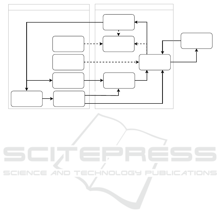
The validation framework is a python library
which starts and controls an instance of OpenRails.
It offers interfaces for a test case and a SuT. The basic
architecture of this framework is shown in Figure 1
and will be explained further in the following.
The test case is composed of a train model to
be controlled, the static information about the world
and infrastructure the test should be conducted in,
the logic to control the dynamics of the test case
(e.g. driving behavior of other trains), and test cri-
teria to determine success or failure of the test. By
expressing test cases as TSCs, we can describe them
on an abstract level, and use instantiation techniques
(Becker et al., 2022) to generate an arbitrary number
of concrete test scenarios. In principle, test criteria
shall be derived from the requirements on the SuT.
This can be done holistically, e.g. via a threshold
on so-called criticality metrics which emerge out of
the traffic situation (Westhofen et al., 2022), or par-
tially via deconstructing the high level requirement
into requirements for sub-systems (Klamann et al.,
2019). Examples for criticality metrics that are of
special interest in the railway domain are: time to
collision (TTC)(Hayward, 1972) which estimates the
minimum time until two entities collide, proportion of
stopping distance (PSD)(Allen et al., 1978) giving the
ratio between the remaining distance of the train to an
obstacle and the minimal distance needed to come to a
stop, brake threat number (BTN)(Jansson, 2005) giv-
ing the normalized necessary acceleration of a train
based on the movement of another entity, and the post
encroachment time (PET)(Allen et al., 1978) which
estimates the time between an entity (e.g. a car) leav-
ing a conflict area (like a level crossing) and the the
train entering it. Criticality metrics can be used to
measure the behavioral safety of a train. Depending
on the use case other metrics measuring efficiency or
passenger comfort can be developed. Grundt et al. in-
2
https://openrails.org/files/OpenRails-Manual.pdf, ver-
sion 1.0.3305
vestigate the suitability of TSCs for the formalization
of requirements and present a concept for monitor-
ing system compliance during validation runs (Grundt
et al., 2022).
The SuT is a controller which can be compared to
the onboard unit for automatic train operation (ATO
On-board) as defined in (ERA et al., 2023), where it
is limited to GoA2. It can be extended to incorporate
tasks currently done by the train driver (Wild et al.,
2023), necessary for GoA3/4.
The main loop of the validation framework in Fig-
ure 1 is shown by the continuous lines: After starting
the test, the SuT sends its control signal to the model
of the ego train, which passes it on to the OpenRails
via the simulator API. Similarly, the dynamic test en-
vironment is updated by the play-out engine using the
information from the test case as well as the current
state of the ego train. When all the control signals
are set, the simulator API triggers a simulator step
of fixed size. Afterward, the simulator sends its new
state to the framework via the simulator API . It will
become necessary to incorporate sensors in the simu-
lation that are not contained in OpenRails, e.g. for ad-
ditional track-side equipment. Therefore, an interface
exists to add custom sensor implementations to the
validation framework. These can process the simula-
tion output from which they can compute their sensor
data. The combined output is returned to the SuT and
all entities that are contained in the simulation. It is
then used to generate the input for the next simulation
step. Since we address the operational level (opposed
to the macroscopic level) of the railway domain, and
test cases shall be atomic, we assume the scenarios
to be local and confined. Therefore the scalability of
the proposed framework to larger networks should not
become an issue.
5 SCENARIO PLAY-OUT
As sketched before, the play-out works on a concrete
scenario derived from the TSC-test. In our case, the
concrete scenario is generated in form of tabular data
containing location information (i.e., position, orien-
tation, size, etc.) for all the objects in the scenario.
This includes the SuT and other traffic participants,
but also the track layout (derived from the TSC),
level crossings, infrastructure (such as signals) and
other relevant static objects (e.g., vegetation along the
track). Beside objects being physically present in the
scene, TSCs can make use of any concept present in
the domain ontology, such as movement authorities
or environmental factors (see (Kramer et al., 2020)
for an example use of environmental factors in TSCs).
A Scenario-Based Simulation Framework for Testing of Highly Automated Railway Systems
91
Simulation State
OpenRails
Test Case
Test Criteria
Concrete Scenario
Dynamic
(e.g. other trains'
movements)
Concrete Scenario
Static
(e.g.track layout)
Ego Train ModelSystem under Test
Validation Framework
Virtual Sensors
Pass/Fail Check
Playout Engine
Simulation API
Simulation State
Commands for all Entities
Simulation state with virtual sensor information
Ego Train Commands
Ego Train State
Figure 1: Flowchart of the simulation framework.
This information is also included in the concrete sce-
nario and can be used for configuring the simulation
setup (e.g., weather parameters) or as inputs to the
SuT (e.g., movement authority).
Earlier work on TSC play-out executes the gen-
erated concrete scenario without reaction on the SuT
(Becker et al., 2022). This may give reliable behav-
ior in automotive scenarios, where the vehicle dynam-
ics can be precisely considered by the TSC solver
(Becker, 2024). The dynamics of trains, on the other
hand, is harder to model due to the increased iner-
tia, as well as different propulsion and braking sys-
tems. At the same time, driving dynamics of road
users are less important. Therefore, we use a novel
approach to adapt the concrete scenario – which we
call reference scenario – during simulation to the be-
havior of the SuT. The intuitive idea is as follows: Be-
cause the SuT is bound to the track it will inevitably
move along the path that is also contained in the ref-
erence scenario. The only way in which the SuT is
expected to diverge from the reference scenario is its
speed—in other words, the timing at which positions
are reached. So, we can adopt the test scenario to the
SuT by adjusting the playback speed. Intuitively, the
reference scenario is delayed if the SuT starts later or
travels with lower speed, and accelerated if it is faster
than expected. Of course, this strategy is only valid
for abstract scenarios (or portions of an abstract sce-
nario) that do not make assumptions about duration
of traffic situations. Therefore, we will provide a way
to apply the time scaling only to portions of the sce-
nario. Alternatively to the time domain, we can alter
positions (and speed) of dynamic environment objects
(road users, other trains) in order to match the refer-
ence scenario relatively to the SuT. Most spatial rela-
tions in an abstract scenario are relative. For example,
if the abstract scenario specifies a distance constraint
between the SuT and a road user, we can control the
road user in a way that its distance to the SuT matches
the distance in the reference scenario. The play-out
engine then uses a variant of model predictive control
(MPC) (Faulwasser and Findeisen, 2015; Schwenzer
et al., 2021) to control both the environment of the
SuT (i.e., other traffic participants and trains) as well
as the play back speed in order to keep the simulation
as close as possible to the reference scenario.
In the following, we sketch the play-out formally.
According to Menzel et al. (Menzel et al., 2018), a
concrete scenario is characterized by a sequence of
scenes and the evolution between them. For the pur-
pose of play-out, we define the terms scene, concrete
scenario and abstract scenario formally.
Definition 1 (Scenario representation). A scene in a
concrete scenario is represented as a vector s ∈R
|Attr|
that has an entry s[a
o
] for every attribute a
o
∈ Attr of
every object o that is present in the scene. The set of
all possible scenes is denoted by Σ ⊆ R
|Attr|
.
A concrete scenario is represented by a function
σ : T → Σ mapping each time point in a closed time
interval T ⊂ R
≥0
to a scene.
The scene σ(t) describes the state of every object
at time point t. For example, having the SuT and a
road user r as objects, σ(t)[v
SuT
] ∈ R is the speed of
the SuT and σ(t)[p
r
] ∈R
2
is the position of r at time t.
We assume that the present objects in the scenario (so,
VEHITS 2025 - 11th International Conference on Vehicle Technology and Intelligent Transport Systems
92

the domain of σ(t)) does not change during the sce-
nario. As stated in Section 2, an abstract scenario A
can subsume an infinite set of concrete scenarios. We
write σ −⊏ A if the concrete scenario σ is an instance
of A. For simplicity, we assume that the same objects
are present in all instances of an abstract scenario, and
the set Σ of scenes is the same for all instances.
A different playback speed can be realized by a
reparametrisation of the time axis of the scenario.
Definition 2. A reparametrisation is a non-
decreasing and bijective function β : T
′
→ T between
two time intervals.
Applying a reparametrisation β : T
1
→T
2
to a sce-
nario σ : T
2
→ Σ yields a scenario σ ◦ β : T
1
→ Σ
with (σ ◦σ)(t) = σ(β(t)). Note, that changing the
playback speed may make some relations between
state variables inconsistent. For example, speed is
usually defined as the length of the position gradient
σ(t)[v] = |
˙
σ(t)[p]|. If we change the playback speed
(i.e., apply some reparametrisation with slope
˙
β(t) ̸=
1), it happens that, for σ
′
= σ ◦β, we get σ
′
(t)[v] =
|
˙
σ(β(t))[p]| ̸= |
˙
σ
′
(t)(p)| =
˙
β(t)|
˙
σ(β(t))[p]|. This in-
consistency is OK, because the reference scenario
contains the expected scenes in some instance of the
abstract scenario and we have to keep the original ob-
ject speed information because it may be subject to a
constraint. Naturally, the play-out engine cannot alter
the playback speed and still obey both the absolute
object positions and speeds from the reference sce-
nario.
Therefore, the play-out algorithm uses a pseudo-
metric d to compare the currently simulated scene
with the scenes in the reference scenario.
Definition 3 (Pseudo-metric). A pseudo-metric d :
Σ × Σ → R
≥0
(sometimes called semi-metric) is a
function that fulfils
d(s
1
,s
1
) = 0
d(s
1
,s
2
) = d(s
2
,s
1
)
d(s
1
,s
3
) ≤ d(s
1
,s
2
) + d(s
2
,s
3
)
for all scenes s
1
,s
2
,s
3
∈ Σ.
This pseudo-metric allows to compare only the as-
pects of the scenes that are relevant for the abstract
scenario (e.g., some relative distance) while ignor-
ing unimportant aspects (e.g., an absolute position or
speed).
Fact 1. For every abstract scenario A there exists
a pseudo-metric d : Σ × Σ → R
≥0
and a set B of
reparametrizations such that for all scenarios σ : T →
Σ,σ
′
: T
′
→ Σ and reparametrizations (β : T → T
′
) ∈
B holds
max
t∈T
d(σ(t),σ
′
(β(t))) = 0 =⇒ (σ −⊏ A ⇔ σ
′
−⊏ A) .
Proof. This trivially holds if we choose an arbitrary
metric d(s,s
′
) = ∥s
′
−s∥ on Σ (i.e., d(s, s
′
) = 0 ⇒
s = s
′
for all s,s
′
∈ Σ), and B = {id
T
} contains the
identity function over T . In this case, σ
′
◦β = σ
′
and
max
t∈T
d(σ(t),σ
′
(t)) = 0 implies σ = σ
′
.
We weaken this constraint by introducing some
form of robustness (cf. (Fr
¨
anzle, 1999)).
Definition 4 (Robust instance). A concrete scenario
σ : T → Σ −⊏ A is a robust instance of A for discretiza-
tion δ > 0 if there exists some known ε > 0 and B such
that, for all σ
′
: T
′
→ Σ and (β : T
′
→ T ) ∈ B,
max
t∈T
′
δ
d(σ
′
(t),σ(β(t))) < ε =⇒σ
′
−⊏ A
with T
′
δ
= {δk ∈T
′
| k ∈N}.
The simulator works at a fixed (configurable) time
step size δ. In each step, it receives simulation
commands and produces the next simulation state S.
Hereby, the commands for controlling the ego train
are produced by the SuT and the commands for con-
trolling the rest of the simulation by environment con-
trollers. The environment controllers in turn receive
their input I from the play-out engine. The play-
out engine uses some function F
δ
(S,I) in closed form
that, from the current simulation state S (that may be
given in form of a scene description according to Defi-
nition 1), forecasts the next scene that will result from
simulating with input I for the environment. As an in-
put, the play-out engine takes the reference scenario
σ : [t
0
,t
e
] → Σ, a (pseudo) metric d, and an interval
B ⊆ R
≥0
that limits the allowed playback speed, e.g.,
B = [1, 1] does not allow any speed-up or slow down,
B = [0,1] allows slow down only, and B = [0,∞) al-
lows any change of playback speed. It keeps track
of the current scenario time t. For the play-out, it is
sufficient to use partial scene descriptions that only
contain values for the objects and attributes that are
relevant for the pseudo-metric d. In particular, static
objects such as the track layout and scenery may be
ignored by the play-out engine, because their position
in the simulation is guaranteed to be the same as in
the reference scenario. Therefore, it is sufficient if the
pseudo-metric compares moving objects to their ab-
solute positions in the reference scenario in order to
assert the relations to static scenery as well.
The play-out is a simple MPC loop given in Al-
gorithm 1. In contrast to standard MPC, a predic-
tion horizon of a single step is used, which is for
efficiency. As a second difference to MPC, we do
not only optimize the controller input I but also the
time progress ∆ on the reference scenario. The sce-
nario time t is increased by ∆, while δ time elapses
in the simulation. So, the playback speed is increased
A Scenario-Based Simulation Framework for Testing of Highly Automated Railway Systems
93

reference scenario
pseudo metric
time scaling interval
Play-out engine
in every step minimize
for s.t.
Simulator
SuT
Environment vehicle
controllers
Figure 2: The scenario play-out.
(or decreased) by the factor δ/∆, which we call time
scaling. In each simulation step, the play-out en-
gine calculates the optimal environment input I and
a time progress ∆ > 0 such that ∆/δ ∈ B, and the dis-
tance between the next scene σ(t +∆) in the reference
scenario and the next (forecast) simulated scene will
be minimal. Our prototype implementation (see Sec-
tion 6) uses some general purpose numeric optimiza-
tion method.
Algorithm 1: The play-out loop.
Data: reference scenario σ : [t
0
,t
e
] → Σ, step
size δ > 0, forecast function F
δ
, time
scaling interval B
Input: Current simulation state S in every
simulation step
Output: Next input for environment
controllers in every step
t ←t
0
;
Initialize the simulation with σ(t
0
);
for every step do
receive simulation state S;
I, ∆ ← arg min
I,∆
d
F
δ
(S,I), σ(t + ∆)
subject to ∆/δ ∈ B;
send input I;
t ←t +∆;
if t > t
e
then stop;
end
The choice of a different scenario time progress
∆ in each simulation step leads to the aforementioned
reparametrization β of the reference scenario. This
reparametrization can be constructed as a piecewise
linear function
β(kδ +t) = t
k
+
t∆
k
δ
for t ∈ [0, δ], k = 0,1,.. .
where t
k
is the scenario time, and ∆
k
= t
k+1
−t
k
the
time progress in simulation step k.
The sketched play-out algorithm can be further
extended to apply different pseudo-metrics and time
scaling intervals B during a scenario. Then, d and
B are replaced by a time-dependent pseudo-metric d
t
and interval B
t
, where t is the current scenario time.
This allows, e.g., to adapt to the SuT behavior only
during some built-up phase of the test scenario, and
control the environment deterministically afterwards
when the reaction of the SuT is tested. An example of
such a time-dependent pseudo-metric is given in the
following section.
6 CASE STUDY: LEVEL
CROSSING
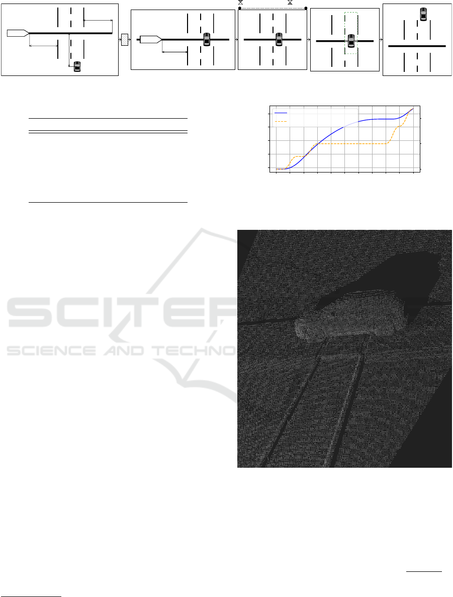
Figure 3 shows a TSC that formalizes the required
behavior of a train as specified in the German train
driver operating instructions (Deutsche Bahn AG,
2015) on an unprotected level crossing. We assume
that the maximum allowed speed on the track section
is 30 km/h (8.33m/s). When approaching, a train has
to:
1. stop in front of the crossing and sound the horn
2. enter the crossing with low speed if the level
crossing is free
3. leave the crossing quickly as soon as the middle
of the road is reached by the first vehicle.
In a TSC, traffic situations are depicted graphi-
cally by placing object symbols inside so-called spa-
tial views. The relative placement of objects in a spa-
tial view indicates spatial relations between the ob-
jects in the scenario. Green dashed somewhere-boxes
indicate a position somewhere in the marked area,
while red dashed and crossed nowhere-boxes denote
absence of objects. Spatial views can be further an-
notated by distances and textual predicates. For ex-
ample, the level crossing being free is specified as ab-
sence of objects on, or vehicles with positive velocity
(v > 0) moving towards the level crossing. Spatial
views can be combined using different operators such
as sequence, choice, parallel composition, and nega-
tion. We refer the interested reader to (Damm et al.,
2018) for a complete description of the TSC formal-
ism.
Figure 4 shows a possible TSC-test for the level
crossing rule. It describes the start, intermediate, and
end situation (the shaded box is an empty spatial view
allowing any behavior). In the beginning, the train is
on the start of the test track, with the level crossing at
least 200 m ahead. A road user is 100 m away from
the level crossing. During the specified scenario, the
VEHITS 2025 - 11th International Conference on Vehicle Technology and Intelligent Transport Systems
94

v = 0 ∧ sounds_horn
< 5m
v > 0
v > 0
v < 5[km/h]
v = 30[km/h] ∨ acc ≥ 0.5[m/s^2]
≥ 2.5m
Figure 3: A TSC that describes the required behavior on a level crossing without barriers.
road user is blocking the level crossing when the train
is more than 30 m and less than 70 m away. The road
user stays there for 15 s. At the end of the specified
scenario, the road user leaves the level crossing. Note,
that the TSC in Figure 4 only describes the test input,
but not the expected reaction of the SuT: Starting with
the third spatial view (from the right), the train is not
shown anymore. In a TSC, this does not mean that it
is not present in the scenario anymore, but that it shall
not be constrained by the depicted scene. So, for eval-
uation of the test case, we need to observe both the
correct execution of TSC-test in Figure 4 and TSC-
requirement in Figure 3.
We make the reasonable assumption that the SuT
is aware of its distance to the unprotected level
crossing. Via its braking curve (European Railway
Agency, 2020) it knows which brake force to apply in
order to safely stop at the level crossing. After the ab-
sence of obstacles is ensured via a lidar sensor model,
the SuT accelerates to 5 km/h until the middle of the
first wagon reaches the level crossing and then clears
it as fast as possible.
The reference scenario for the test execution is
derived from the TSC-test via constraint solving as
sketched in (Becker et al., 2022; Becker, 2024). This
approach ensures that the movement of the road user
in the reference scenario is smooth. Since realistic
driving physics of the road user are uncritical for val-
idation of the SuT
3
, we refrain from simulating the
road user with a physics engine. Instead, the road
user controller sends simulation commands that di-
rectly update its position.
The play-out algorithm has been implemented in
Python using the minimize function (with default pa-
rameters) from the SciPy package (Virtanen et al.,
2020) for bounded optimization of the control values.
The controller input to be optimized by the play-out
engine is the road user position I = (x
′
r
,y
′
r
) for the
3
One may even argue that the SuT shall be able to react
to road users that behave in an unexpected way.
next simulation step. The relevant part of the simula-
tion state S = (x
e
,v
e
,x
r
,y
r
) consists of the ego train’s
x-position and speed, as well as the current road user
position. Each scene in the reference scenario is de-
scribed as a vector s =
x
e
x
r
y
r
T
. Other at-
tributes are not relevant for the scenario and therefore
omitted from the scene description. Furthermore, we
can omit the position of the level crossing, because it
is guaranteed to be the same as in the reference sce-
nario. We use a simple forecast function
F
δ
(S,I) :=
x
e
+ δv
e
x
′
r
y
′
r
T
that extrapolates the train position by its current
speed, and and otherwise assumes that the road user
position can be precisely set.
The pseudo-metric and the allowed slope of the
reparametrizations (i.e., the time scaling) depend on
the current spatial view in TSC-test. Therefore, we
split the time domain of the reference scenario in six
intervals that correspond to the spatial views in Fig-
ure 4 (note that the empty spatial view is included).
For each interval we define a pseudo-metric and time
scaling interval. The pseudo-metric d
t
is the weighted
square pseudo-metric d
t
(s,s
′
) = (x
T
t
(s
′
−s))
2
. Here,
the row vector x
T
t
=
a
t
1 1
defines a variable
weight a
t
for the train position and weights the road
user position with 1. The values for a
t
and B
t
are
listed in Table 1. Note that, starting with the fourth
spatial view in Figure 4, the train behavior is not spec-
ified and therefore the corresponding a
t
are zero. This
makes the control of the road user independent from
the SuT behavior and ensures a meaningful test evalu-
ation in case the SuT fails to stop in front of the level
crossing. The chosen time scaling intervals B
t
sup-
press time scaling during the time-constrained spatial
view, and allow any change of the playback speed oth-
erwise. However, the upper bound 1 + (45s −t)/δ of
B
t
for t < 45 s ensures that the time progress is lim-
ited to t + ∆ ≤ 45 s + δ and cannot range more than
δ into the time-constrained spatial view that starts at
t = 45 s.
A Scenario-Based Simulation Framework for Testing of Highly Automated Railway Systems
95
≥ 200m
= 200m
=100m
∈ [30m, 70m]
d d≥15s
Figure 4: A TSC describing a test scenario with a blocked, unprotected level crossing.
Table 1: Parameters for play-out.
t ∈ a
t
B
t
[ 0 s, 5 s) 1 [0,1 + (45 s −t)/δ]
[ 5 s, 40 s) 1 [0,1 + (45 s −t)/δ]
[40s, 45s) 1 [0,1 + (45s −t)/δ]
[45s, 80s) 0 [1,1]
[80s, 95s) 0 [0,∞)
[95s, 100 s] 0 [0,∞)
7 TEST EVALUATION
In Figure 5 the positions of the ego train and the car
in the reference scenario are shown. Note, that the
road is orthogonal to the railway track, so the road
user x-position remains constant and is not shown in
the figure. This scenario satisfies TSC-test by con-
struction. The SuT which is controlling the train is
implemented as a state-machine
4
with specific states
and transition rules. We assume knowledge of the
position of the unprotected level crossing, which has
to be treated as the end of the train’s movement au-
thority (EOA) (European Union, 2023). The (sub-
)controllers in the specific states are implemented
as proportional–integral–derivative (PID) controllers.
The states include approaching, braking, slow cross-
ing, and leaving. The transition rules include a cross-
ing free check, which uses the emulated lidar sensor
Figure 6. To estimate when we need to transition to
the braking phase we use braking curves which were
previously recorded using the simulator for our spe-
cific consist
5
. Based on the braking curves we derive
the set point (in the form of target velocities) for the
PID-controller.
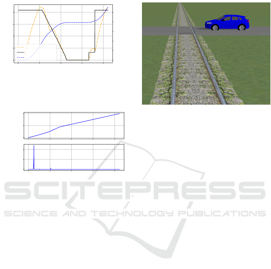
In Figure 7 we see the result of the behavior of the
SuT in the form of its velocity and position, as well as
the set velocity for the PID controller. The different
states can be identified via the different set velocities.
The step size δ was set to 100 ms.
The test evaluation is twofold. Firstly, we check
if the test case was left via the metric introduced in
4
https://pypi.org/project/python-statemachine/
5
a specific arrangement of locomotives and railcars that
make up a train is called a consist
0 10 20 30 40 50 60 70 80 90 100
time in s
−350
−300
−250
−200
−150
x-position in m
−100
0
100
y-position in m
x-position train in m
y-position road user in m
Figure 5: Positions of the ego train (blue solid line) and the
road user (orange dashed line) in the reference scenario.
Figure 6: Emulated lidar point cloud of the car on
the level crossing. Visualized with WebLabel Player
(https://github.com/Vicomtech/weblabel) published by Vi-
comtech Research Foundation.
section 5. As can be see in Figure 8 (bottom plot), the
scenario discrepancy is below 0.015m
2
in all simula-
tion steps. Recalling that the used pseudo-metric is
based on a square norm, this means that the positions
of train and road user deviate at most by
√
0.015m
2
≊
12cm from the reference scenario. In fact, the peak at
t = 5s in Figure 8 is a numerical artefact: Due to the
low acceleration of the train in the beginning of the
reference scenario, the numerical solver fails to find
VEHITS 2025 - 11th International Conference on Vehicle Technology and Intelligent Transport Systems
96
0 20 40 60 80
time in s
0
2
4
6
8
velocity in m/s
0
50
100
150
200
250
position in m
velocity in m/s
set velocity in m/s
position in m
Figure 7: Behavior of the SuT. The black solid line shows
the set velocity for the PID controller, the orange dash-dot
line the actual velocity and the dashed blue line the position
of the ego train.
0
50
100
scenario time in s
0 20 40 60 80
simulation time in s
0.000
0.005
0.010
scenario discrepancy
in m
2
Figure 8: Time scaling and scenario discrepancy.
the exact optimum. However, we consider this devi-
ation to be small enough that the reference scenario
could successfully be adapted to the behavior of the
SuT.
Secondly, we check if TSC-requirement (Fig-
ure 4) is obeyed. For now, this is done visually by
person via observing how the simulation unfolds via
the emulated RGB camera image shown in Figure 9.
We verify that the ego train stops in front of the level
crossing when blocked by a road user and continues
the journey when the level crossing if free. In the fu-
ture we will investigate the use of TSC monitors as
described by Grundt et al. (Grundt et al., 2022) for
this purpose.
8 CONCLUSION AND FUTURE
WORK
In this work we introduced a novel method for play-
out using temporal rescaling which assures that a test-
case specified using a TSC is not left. We further pre-
sented our closed-loop simulation framework for test-
ing. We demonstrated the applicability of OpenRails
as a simulator for this purpose by testing a simple SuT
Figure 9: Emulated RGB camera image showing the car
approaching the level crossing.
which is based on PID-controllers.
In the future, we will model additional abstract
scenarios formalizing different required behaviors of
the ego train, as well as the respective test cases. Fu-
ture scenarios may contain multiple trains, e.g. for
testing virtual coupling of two or more trains. This
will require additional controllers and test-criteria.
Also, more sophisticated controllers for the existing
level-crossing example shall be tested.
Future experiments will also lead to improvement
of the play-out engine. For the level-crossing exam-
ple, quite simple models are sufficient. In future, we
will apply the play-out engine to more complex sce-
narios. This induces several research questions, for
example, whether the control strategy is applicable
to environment objects with a higher degree of free-
dom (e.g., steered vehicles) and whether the play-out
can benefit from a larger prediction horizon. Further-
more, for more complex models, a sensitivity analysis
(Sobieszczanski-Sobieski, 1990) shall be carried out.
In the current implementation, the pseudo-metric and
time scaling intervals need to be hand-crafted by the
engineer according to the scenario. Because not every
pseudo-metric leads to a correct playout, this requires
a deep understanding of the scenario and the playout
approach. For future versions, we will investigate into
an automation of this step, based on the TSC formal
semantics. This will drastically improve the usability
while ensuring both correctness and maximum flexi-
bility during test case execution.
ACKNOWLEDGEMENTS
This project has received funding from the European
Union’s Horizon Europe research and innovation pro-
A Scenario-Based Simulation Framework for Testing of Highly Automated Railway Systems
97

gramme within the projects ‘MOTIONAL’ (under
grant agreement No: 101101973) and ‘Pods4Rail’
(under grant agreement No: 101121853).
REFERENCES
Allen, B. L., Shin, B. T., and Cooper, P. J. (1978). Anal-
ysis of traffic conflicts and collisions. Transportation
Research Record.
Arcaini, P., Kofro
ˇ
n, J., and Je
ˇ
zek, P. (2020). Validation
of the hybrid ERTMS/ETCS level 3 using spin. In-
ternational Journal on Software Tools for Technology
Transfer, 22(3).
Bach, J., Holz
¨
apfel, M., Otten, S., and Sax, E. (2017).
Reactive-replay approach for verification and valida-
tion of closed-loop control systems in early develop-
ment. pages 2017–01–1671.
Basile, D., ter Beek, M. H., Ferrari, A., and Legay, A.
(2022). Exploring the ertms/etcs full moving block
specification: an experience with formal methods.
24(3):351–370. PII: 653.
Becker, J. S. (2024). Safe linear encoding of vehicle dynam-
ics for the instantiation of abstract scenarios. In For-
mal Methods for Industrial Critical Systems (FMICS),
volume 14952 of LNCS. Springer.
Becker, J. S., Koopmann, T., Neurohr, B., Neurohr, C.,
Westhofen, L., Wirtz, B., B
¨
ode, E., and Damm, W.
(2022). Simulation of abstract scenarios: Towards au-
tomated tooling in criticality analysis. SATW.
Boockmeyer, A., Friedenberger, D., and Pirl, L. (2024). Us-
ing sumo for test automation and demonstration of
digitalized railway concepts: Integrating sumo with
the“ train dispatcher in the cloud”. In SUMO Confer-
ence Proceedings, volume 5, pages 195–207.
Borchers, P., Koopmann, T., Westhofen, L., Becker, J. S.,
Putze, L., Grundt, D., de Graaff, T., Kalwa, V.,
and Neurohr, C. (2025). TSC2CARLA: An abstract
scenario-based verification toolchain for automated
driving systems. Science of Computer Programming,
242.
Braband, J., Evers, B., Kinas, M., Lindner, L., Mihailescu-
Stoica, D., Rexin, F., Adebahr, F., Milius, B., and
Sch
¨
abe, H. (2023). Risikoakzeptanzkriterien f
¨
ur
das automatisierte Fahren auf der Schiene. Techni-
cal report, Deutsches Zentrum f
¨
ur Schienenverkehrs-
forschung beim Eisenbahn-Bundesamt.
Cimatti, A., Giunchiglia, F., Mongardi, G., Romano, D., To-
rielli, F., and Traverso, P. (1998). Formal verification
of a railway interlocking system using model check-
ing. 10(4):361–380.
D’Amico, G., Marinoni, M., Nesti, F., Rossolini, G., But-
tazzo, G., Sabina, S., and Lauro, G. (28.02.2023).
Trainsim: A railway simulation framework for lidar
and camera dataset generation. Under review.
Damm, W., M
¨
ohlmann, E., Peikenkamp, T., and Rakow,
A. (2018). A Formal Semantics for Traffic Sequence
Charts, pages 182–205. Springer International Pub-
lishing, Cham.
Damm, W., M
¨
ohlmann, E., and Rakow, A. (2020a). A
scenario discovery process based on traffic sequence
charts. In Leitner, A., Watzenig, D., and Ibanez-
Guzman, J., editors, Validation and Verification of Au-
tomated Systems, pages 61–73. Springer International
Publishing.
Damm, W., M
¨
ohlmann, E., and Rakow, A. (2020b). Traf-
fic sequence charts for the enable-s3 test architecture.
In Leitner, A., Watzenig, D., and Ibanez-Guzman, J.,
editors, Validation and Verification of Automated Sys-
tems, pages 45–60. Springer International Publishing.
Decker, T., Bhattarai, A. R., and Lebacher, M. (2023).
Towards scenario-based safety validation for au-
tonomous trains with deep generative models. In
Computer Safety, Reliability, and Security, pages 273–
281. Springer.
Deutsche Bahn AG (2015). Fahrdienstvorschrift richtlinie
408.21-27: Z
¨
uge fahren.
Deutsches Zentrum f
¨
ur Luft- und Raumfahrt e.V. (2016).
Railsite (rail simulation and testing). 2(A88).
ERA, UNISIG, EEIG, and GROUP, E. U. (2023). Ertms/ato
system requirements specification.
European Railway Agency (2020). Introduction to ETCS
braking curves.
European Union (2023). Commission implementing regu-
lation (EU) 2019/773 of 16 may 2019 on the technical
specification for interoperability relating to the opera-
tion and traffic management subsystem of the rail sys-
tem within the european union and repealing decision
2012/757/EU.
Faulwasser, T. and Findeisen, R. (2015). Nonlinear model
predictive control for constrained output path fol-
lowing. IEEE Transactions on Automatic Control,
61(4):1026–1039.
Foretellix Ltd. (2020). Measurable scenario descrip-
tion language reference. Technical report, Foretellix
Ltd. https://www.foretellix.com/wp-content/uploads/
2020/07/M-SDL
LRM OS.pdf, accessed on 2024-04-
19.
Fr
¨
anzle, M. (1999). Analysis of hybrid systems: An ounce
of realism can save an infinity of states. In Flum, J. and
Rodriguez-Artalejo, M., editors, Computer Science
Logic, pages 126–139, Berlin, Heidelberg. Springer
Berlin Heidelberg.
Fremont, D. J., Kim, E., Dreossi, T., Ghosh, S., Yue,
X., Sangiovanni-Vincentelli, A. L., and Seshia, S. A.
(2023). Scenic: a language for scenario specification
and data generation. 112(10):3805–3849.
Geischberger, J. and Weik, N. (2022). Combining operative
train simulation with logistics simulation in sumo. In
SUMO User Conference 2022, volume 3.
Grossmann, J., Grube, N., Kharma, S., Knoblauch, D.,
Krajewski, R., Kucheiko, M., and Wiesbrock, H.-W.
(2023). Test and training data generation for object
recognition in the railway domain. In Software Engi-
neering and Formal Methods. SEFM 2022 Collocated
Workshops, volume 13765 of LNCS. Springer.
Grundt, D., K
¨
ohne, A., Saxena, I., Stemmer, R., West-
phal, B., and M
¨
ohlmann, E. (2022). Towards runtime
VEHITS 2025 - 11th International Conference on Vehicle Technology and Intelligent Transport Systems
98

monitoring of complex system requirements for au-
tonomous driving functions.
Hampel, F. O., Morast, A., Nießen, N., and Schindler, C.
(2021). Automatischer Eisenbahnverkehr: Aufgaben
des Triebfahrzeugf
¨
uhrers am Beispiel der Strecken-
beobachtung. In Proceedings of the 3rd International
Railway Symposium Aachen, page 367.
Haxthausen, A. E. and Fantechi, A. (2023). Compositional
verification of railway interlocking systems. Formal
Aspects of Computing, 35(1):1–46.
Hayward, J. C. (1972). Near-miss determination through
use of a scale of danger. Highway Research Record.
HENSOLDT (2023). Simsphere train. Accessed
April 11, 2023. https://www.hensoldt.net/stories/
training-train-drivers-etcs-app-by-hensoldt/.
H
¨
olscher, C. (2023). Zusi bahnsimulatoren. Accessed April
11, 2023. https://www.zusi.de.
Issad, M., Kloul, L., and Rauzy, A. (2018). Scenario-
oriented reverse engineering of complex railway sys-
tem specifications. 21(2):91–104.
Jansson, J. (2005). Collision avoidance theory: With appli-
cation to automotive collision mitigation. PhD Thesis,
Link
¨
oping University.
Kalisvaart, S., Slavik, Z., and Op den Camp, O. (2020). Us-
ing scenarios in safety validation of automated sys-
tems. In Validation and Verification of Automated Sys-
tems. Springer.
Kearney, J., Willemsen, P., Donikian, S., and Devillers, F.
(1999). Scenario languages for driving simulation. In
Driving Simulation Conference, DSC’99.
Klamann, B., Lippert, M., Amersbach, C., and Winner, H.
(2019). Defining Pass-/Fail-Criteria for Particular
Tests of Automated Driving Functions. Pages: 174.
Koopman, P. and Wagner, M. (2018). Toward a framework
for highly automated vehicle safety validation. In
WCX World Congress Experience. SAE International.
Kramer, B., Neurohr, C., B
¨
uker, M., B
¨
ode, E., Fr
¨
anzle, M.,
and Damm, W. (2020). Identification and quantifica-
tion of hazardous scenarios for automated driving. In
International symposium on model-based safety and
assessment, pages 163–178. Springer.
Krichen, M., Mihoub, A., Alzahrani, M. Y., Adoni, W.
Y. H., and Nahhal, T. (2022). Are formal methods
applicable to machine learning and artificial intelli-
gence? In 2nd International Conference of Smart Sys-
tems and Emerging Technologies (SMARTTECH).
Leitner, A. (2020). Enable-s3: Project introduction. In
Validation and Verification of Automated Systems.
Springer.
Menzel, T., Bagschik, G., and Maurer, M. (2018). Scenarios
for development, test and validation of automated ve-
hicles. In 2018 IEEE Intelligent Vehicles Symposium
(IV), pages 1821–1827. IEEE.
M
¨
uller Systemtechnik (2023). Mst trieb-
fahrzeug simulator. Accessed April 11,
2023. https://muellersystemtechnik.de/
mst-triebfahrzeug-simulator.
Neurohr, C., Westhofen, L., Butz, M., Bollmann, M. H.,
Eberle, U., and Galbas, R. (2021). Criticality analysis
for the verification and validation of automated vehi-
cles. 9:18016–18041.
Neurohr, C., Westhofen, L., Henning, T., de Graaff, T.,
M
¨
ohlmann, E., and B
¨
ode, E. (2020). Fundamental
considerations around scenario-based testing for au-
tomated driving. In 2020 IEEE Intelligent Vehicles
Symposium (IV), pages 121–127. IEEE.
Rauschert, A. and Amid, G. (2024a). ASAM OpenSCE-
NARIO DSL 2.1.0: Release presentation. Presenta-
tion. Last accessed on 2024-05-08.
Rauschert, A. and Amid, G. (2024b). ASAM OpenSCE-
NARIO XML 1.3.0: Release presentation. Presenta-
tion. Last accessed on 2024-05-08.
Riedmaier, S., Ponn, T., Ludwig, D., Schick, B., and Dier-
meyer, F. (2020). Survey on scenario-based safety as-
sessment of automated vehicles. 8:87456–87477.
Schwenzer, M., Ay, M., Bergs, T., and Abel, D. (2021).
Review on model predictive control: An engineering
perspective. The International Journal of Advanced
Manufacturing Technology, 117(5):1327–1349.
Sch
¨
afer, S., Greiner-Fuchs, L., Hofmeier, T., Koch, P., and
Cichon, M. (2023). Virtual validation method of au-
tomated on-sight driving systems for shunting opera-
tions.
Sobieszczanski-Sobieski, J. (1990). Sensitivity of complex,
internally coupled systems. AIAA journal, 28(1):153–
160.
Tagiew, R., Leinhos, D., von der Haar, H., Klotz, C., Sprute,
D., Ziehn, J., Schmelter, A., Witte, S., and Klasek, P.
(2022). Onboard sensor systems for automatic train
operation. In Dependable Computing – EDCC 2022
Workshops, volume 1656 of Communications in Com-
puter and Information Science. Springer.
Virtanen, P., Gommers, R., Oliphant, T. E., Haberland, M.,
Reddy, T., Cournapeau, D., Burovski, E., Peterson,
P., Weckesser, W., Bright, J., et al. (2020). Scipy
1.0: fundamental algorithms for scientific computing
in python. Nature methods, 17(3):261–272.
Westhofen, L., Neurohr, C., Koopmann, T., Butz, M.,
Sch
¨
utt, B., Utesch, F., Neurohr, B., Gutenkunst, C.,
and B
¨
ode, E. (2022). Criticality metrics for automated
driving: A review and suitability analysis of the state
of the art.
Wild, M., Becker, J. S., Ehmen, G., and M
¨
ohlmann, E.
(2023). Towards scenario-based certification of highly
automated railway systems. In Reliability, Safety, and
Security of Railway Systems, LNCS. Springer.
Yusuf, M., MacDonald, A., Stuart, R., and Miyazaki, H.
(2020). Heavy haul freight transportation system: Au-
tohaul. Technical report.
A Scenario-Based Simulation Framework for Testing of Highly Automated Railway Systems
99
